Component Based Diagram Unified Modeling Language (UML) (original) (raw)
Last Updated : 15 Jul, 2025
Component-based diagrams are essential tools in software engineering, providing a visual representation of a system's structure by showcasing its various components and their interactions. These diagrams simplify complex systems, making it easier for developers to design, understand, and communicate the architecture.

Component Based Diagram
Table of Content
- What is a Component-Based Diagram?
- Components of Component-Based Diagram
- Steps to Create Component-Based Diagrams
- Best practices for creating Component Based Diagrams
- Example of Component Based Diagram
- Tools and Software available for Component-Based Diagrams
- Applications of Component-Based Diagrams
- Benefits of Using Component-Based Diagrams
What is a Component-Based Diagram?
One kind of structural diagram in the Unified Modeling Language (UML) that shows how the components of a system are arranged and relate to one another is termed a component-based diagram, or simply a component diagram.
- System components are modular units that offer a set of interfaces and encapsulate implementation.
- These diagrams illustrate how components are wired together to form larger systems, detailing their dependencies and interactions.
Component-Based Diagrams are widely used in system design to promote modularity, enhance understanding of system architecture****.**
Components of Component-Based Diagram
Component-Based Diagrams in UML comprise several key elements, each serving a distinct role in illustrating the system’s architecture. Here are the main components and their roles:
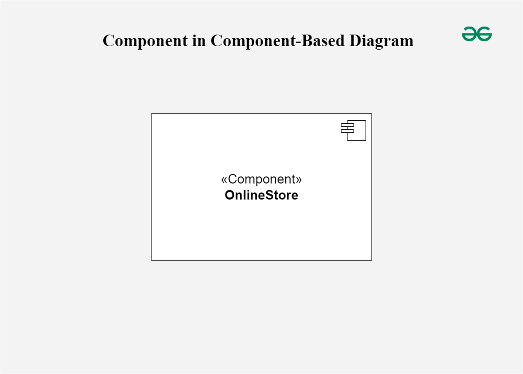
**1. Component
Represent modular parts of the system that encapsulate functionalities. Components can be software classes, collections of classes, or subsystems.
- **Symbol: Rectangles with the component stereotype («component»).
- **Function: Define and encapsulate functionality, ensuring modularity and reusability.
Component
**2. Interfaces
Specify a set of operations that a component offers or requires, serving as a contract between the component and its environment.
- **Symbol: Circles (lollipops) for provided interfaces and half-circles (sockets) for required interfaces.
- **Function: Define how components communicate with each other, ensuring that components can be developed and maintained independently.

Interfaces
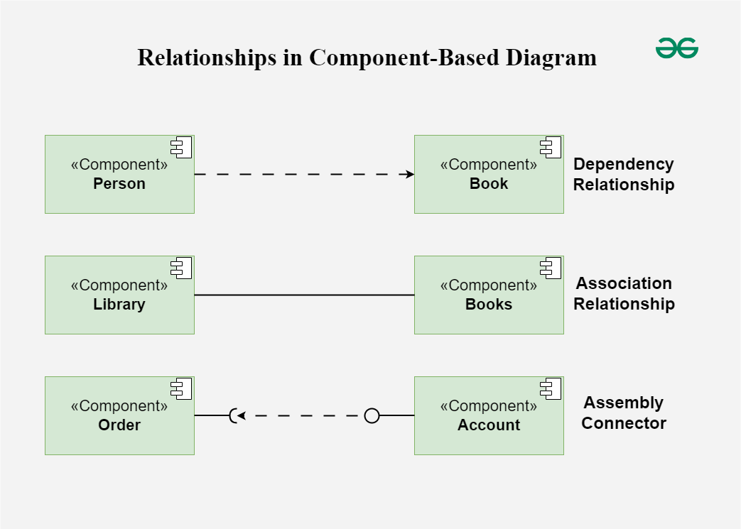
**3. Relationships
Depict the connections and dependencies between components and interfaces.
- **Symbol: Lines and arrows.
- **Dependency (dashed arrow): Indicates that one component relies on another.
- **Association (solid line): Shows a more permanent relationship between components.
- **Assembly connector: Connects a required interface of one component to a provided interface of another.
- **Function: Visualize how components interact and depend on each other, highlighting communication paths and potential points of failure.
Relationships
**4. Ports
**Role: Represent specific interaction points on the boundary of a component where interfaces are provided or required.
- **Symbol: Small squares on the component boundary.
- **Function: Allow for more precise specification of interaction points, facilitating detailed design and implementation.

Ports
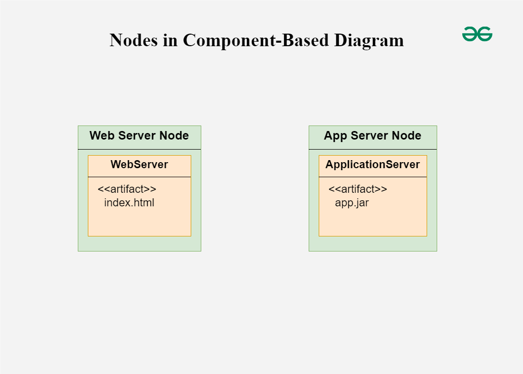
**5. Artifacts
Represent physical files or data that are deployed on nodes.
- **Symbol: Rectangles with the artifact stereotype («artifact»).
- **Function: Show how software artifacts, like executables or data files, relate to the components.

Artifacts
**6. Nodes
Represent physical or virtual execution environments where components are deployed.
- **Symbol: 3D boxes.
- **Function: Provide context for deployment, showing where components reside and execute within the system’s infrastructure.
Nodes
Steps to Create Component-Based Diagrams
From understanding the system requirements to creating the final design, there are multiple processes involved in creating a component-based diagram. These steps will assist you in creating the ideal component-based diagram:
- **Step 1: **Identify the System Scope and Requirements:
- **Understand the system: Get as much information as you can on the requirements, limitations, and functionality of the system.
- **Define the boundaries: Determine what parts of the system will be included in the diagram.
- **Step 2: **Identify and Define Components:
- **List components: Identify all the major components that make up the system.
- **Detail functionality: Define the responsibilities and functionalities of each component.
- **Encapsulation: Ensure each component encapsulates a specific set of functionalities.
- **Step 3: **Identify Provided and Required Interfaces:
- **Provided Interfaces: Determine what services or functionalities each component provides to other components.
- **Required Interfaces: Identify what services or functionalities each component requires from other components.
- **Define Interfaces: Clearly define the operations included in each interface.
- **Step 4: **Identify Relationships and Dependencies:
- **Determine connections: Identify how components are connected and interact with each other.
- **Specify dependencies: Outline the dependencies between components, including which components rely on others to function.
- **Step 5: Identify Artifacts:
- **List artifacts: Identify the physical pieces of information (files, documents, executables) associated with each component.
- **Map artifacts: Determine how these artifacts are deployed and used by the components.
- **Step 6: Identify Nodes:
- **Execution environments: Identify the physical or virtual nodes where components will be deployed.
- **Define nodes: Detail the hardware or infrastructure specifications for each node.
- **Step 7: Draw the Diagram:
- **Use a UML tool: Make use of any UML software, such as Lucidchart, Microsoft Visio, or another UML diagramming tool.
- **Draw components: Represent each component as a rectangle with the «component» stereotype.
- **Draw interfaces: Use lollipop symbols for provided interfaces and socket symbols for required interfaces.
- **Connect components: Use assembly connectors to link provided interfaces to required interfaces.
- **Add artifacts: Represent artifacts as rectangles with the «artifact» stereotype and associate them with the appropriate components.
- **Draw nodes: Represent nodes as 3D boxes and place the components and artifacts within these nodes to show deployment.
- **Step 8: Review and Refine the Diagram:
- **Validate accuracy: Ensure all components, interfaces, and relationships are accurately represented.
- **Seek feedback: Review the diagram with stakeholders or team members to ensure it meets the system requirements.
- **Refine as needed: Make necessary adjustments based on feedback to improve clarity and accuracy.
Best practices for creating Component Based Diagrams
Several best practices are used while creating component-based diagrams to guarantee that the system's architecture is communicated accurately, clearly, and effectively. Here are some guidelines for best practices:
- **Understand the System:
- Before drawing the design, make sure you fully understand the needs, features, and limitations of the system.
- Work closely with stakeholders to gather requirements and clarify any ambiguities.
- **Keep it Simple:
- Aim for simplicity and clarity in the diagram. Avoid unnecessary complexity that may confuse readers.
- Break down the system into manageable components and focus on representing the most important aspects of the architecture.
- **Use Consistent Naming Conventions:
- Use consistent and meaningful names for components, interfaces, artifacts, and nodes.
- Follow a naming convention that reflects the system's domain and is understandable to all stakeholders.
- **Define Clear Interfaces:
- Clearly define the interfaces provided and required by each component.
- Specify the operations and functionalities exposed by each interface in a concise and understandable manner.
- **Use Stereotypes and Annotations:
- Use UML stereotypes and annotations to provide additional information about components, interfaces, and relationships.
- For example, use stereotypes like «component», «interface», «artifact», etc., to denote different elements in the diagram.
Example of Component Based Diagram
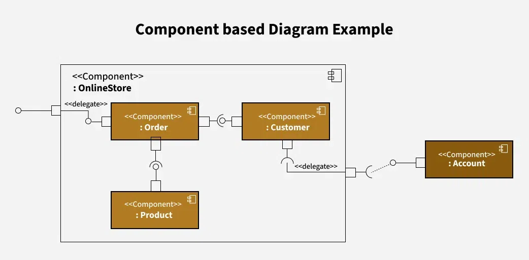
This component diagram represents an **Online Store system, breaking it down into various functional components and showing how they interact. Here’s a breakdown of each part:
Example of Component Based Diagram
- **OnlineStore Component: This is the main component encapsulating the entire system. It includes three internal components: **Order, **Customer, and **Product.
- **Order Component: This component handles order-related operations within the Online Store. It is connected to:
- The **Product component (which likely manages details of products in each order).
- The **Customer component (for associating orders with customers).
- External access points via **delegates (marked by
<<delegate>>notation), which indicate that certain internal actions can be routed or passed on to other parts.
- **Customer Component: This component manages customer-related data and activities.
- It’s connected to the **Order component to handle customer orders.
- The **Account component (outside of **OnlineStore) is connected to **Customer through a **delegate, suggesting that customer-related actions in **OnlineStore might involve account information from another system.
- **Product Component: This component manages product-related functions within the Online Store.
- It’s linked to the **Order component, allowing orders to reference available products.
- **Account Component: This component is located outside the **OnlineStore boundary, indicating it may be a separate system or module. It connects to **Customer through a dotted line with a delegate, showing that **OnlineStore can delegate certain account-related functions to this external **Account component.
Several tools and software are available for creating Component-Based Diagrams, ranging from general-purpose diagramming tools to specialized UML modeling software. Here are some popular options:
- **Lucidchart: Lucidchart is a cloud-based diagramming tool that supports creating various types of diagrams, including Component-Based Diagrams.
- **Microsoft Visio: Microsoft Visio is a versatile diagramming tool that supports creating Component-Based Diagrams and other types of UML diagrams.
- **Visual Paradigm: Visual Paradigm is a comprehensive UML modeling tool that supports the creation of Component-Based Diagrams, along with other UML diagrams.
- **Enterprise Architect: Enterprise Architect is a powerful UML modeling and design tool used for creating Component-Based Diagrams and other software engineering diagrams.
- **IBM Rational Software Architect: IBM Rational Software Architect is an integrated development environment (IDE) for modeling, designing, and developing software systems.
**Applications of Component-Based Diagrams
As they facilitate communication, documentation, and system design, component-based diagrams are crucial to software development. These are some important applications for them:
- **System Design and Architecture: By displaying the parts (components), their connections, and any dependencies between them, these diagrams help architects and designers in understanding the structure of a system.
- **Requirements Analysis: These diagrams help clients and developers in understanding the functional (what the system should accomplish) and non-functional (performance, security, etc.) requirements of the system.
- **System Documentation: Component-Based Diagrams act as useful records of how the system is built, capturing big-picture design and architectural decisions for future reference.
- **Software Development: These diagrams guide developers during the build phase, clearly outlining component boundaries and how different parts of the software should interact.
- **Code Generation and Implementation: Sometimes, these diagrams can be a starting point for generating code automatically, speeding up the process of building out the software components.
- **System Maintenance and Evolution: As the system grows or changes, these diagrams are helpful for understanding the current architecture, making updates easier and more organized.
Benefits of Using Component-Based Diagrams
Throughout the software development lifecycle, using component-based diagrams helps with software system design, communication, and maintenance. Here are a few main benefits:
- **Visualization of System Architecture: Component-Based Diagrams give the architecture of the system, including its dependencies, interfaces, and components, a visual representation.
- **Modularity and Reusability: By dividing complex structures into more manageable, reusable parts, component-based diagrams encourage modularity.
- **Improved Communication: A consistent visual language for communication between project managers, developers, architects, and testers is provided by component-based diagrams.
- **Ease of Maintenance and Evolution: Component-Based Diagrams help in system maintenance and evolution by providing a clear documentation of system architecture.
- **Enforcement of Design Principles: Component-Based Diagrams help enforce design principles such as encapsulation, cohesion, and loose coupling.