designMultirateFIR - Design and implement antialiasing and anti-imaging lowpass FIR filter - MATLAB (original) (raw)
Design and implement antialiasing and anti-imaging lowpass FIR filter
Syntax
Description
[B](#bu36evg-1-B) = designMultirateFIR designs a multirate FIR filter. The output B is a vector of filter coefficients. To implement the filter, you must assign the filter coefficientsB to a multirate filter object.
The multirate FIR filter is an antialiasing and anti-imaging lowpass FIR filter used in digital rate conversion.
[B](#bu36evg-1-B) = designMultirateFIR([Name=Value](#namevaluepairarguments)) specifies options using one or more name-value arguments. (since R2024a)
For example, `B` =`designMultirateFIR`([InterpolationFactor](#bu36evg-1-L)=3,[DecimationFactor](#bu36evg-1-M)=2,[SystemObject](#mw%5Ff0e59c9c-61d9-4dbb-84f8-07e402f0adb3)=true) designs an FIR rate converter with the interpolation factor of 3, decimation factor of 2, polyphase length of 24, and the stopband attenuation of 80 dB. As theSystemObject argument is true, the function returns a dsp.FIRRateConverter System object™.
When you specify only a partial list of filter parameters, the function designs the filter by setting the other design parameters to their default values.
When you specify any of the numeric input arguments in single precision, the function designs the filter coefficients in single precision. Alternatively, you can use the Datatype and like arguments to control the data type of the coefficients. (since R2024b)
Examples
To design an FIR interpolator using the designMultirateFIR function, specify the interpolation factor (usually a value greater than 1) and set the decimation factor to 1. You can use the default polyphase length and stopband attenuation or you can use nondefault values.
Design an FIR interpolator with the interpolation factor of 5. Use the default polyphase length of 24 and the default stopband attenuation of 80 dB.
b = designMultirateFIR(InterpolationFactor=5,DecimationFactor=1); impz(b)

Design a polyphase FIR interpolator by using the designMultirateFIR function with the interpolation factor of 5, normalized transition width of 0.01, and stopband attenuation of 60 dB. Set the 'SystemObject' argument to true to create a dsp.FIRInterpolator object. To design the filter in single-precision, use the Datatype or like argument. Alternatively, you can specify any of the numerical arguments in single-precision.
firInterp = designMultirateFIR(InterpolationFactor=5,... TransitionWidth=0.01,... StopbandAttenuation=60,... Datatype="single",... SystemObject=true,... Verbose=true)
designMultirateFIR(InterpolationFactor=5, DecimationFactor=1, TransitionWidth=0.01, InputSampleRate="normalized", OverlapTransition=true, DesignMethod="kaiser", StopbandAttenuation=60, Datatype="single", SystemObject=true)
firInterp = dsp.FIRInterpolator with properties:
InterpolationFactor: 5
    NumeratorSource: 'Property'
          Numerator: [8.5015e-05 8.9039e-05 5.7574e-05 0 -6.2845e-05 -1.0610e-04 -1.1061e-04 -7.1214e-05 0 7.7112e-05 1.2970e-04 1.3474e-04 8.6452e-05 0 -9.3019e-05 -1.5599e-04 -1.6159e-04 -1.0340e-04 0 1.1067e-04 1.8515e-04 … ] (1×727 single)
Show all properties
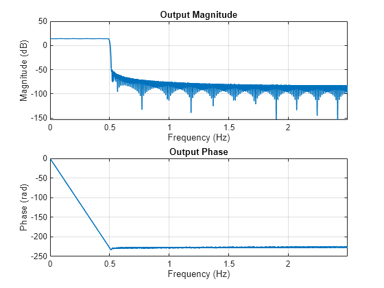
Visualize the magnitude and phase response of the FIR interpolator using the freqzmr function. The response curves show the magnitude and phase responses of a linearly interpolated filter.
Compute the cost of implementing the filter.
ans = struct with fields: NumCoefficients: 582 NumStates: 145 MultiplicationsPerInputSample: 582 AdditionsPerInputSample: 578
Measure the frequency response characteristics of the filter object.
ans =
Sample Rate : N/A (normalized frequency)
Passband Edge : 0.195
3-dB Point : 0.19884
6-dB Point : 0.2
Stopband Edge : 0.205
Passband Ripple : 0.016474 dB
Stopband Atten. : 60.183 dB
Transition Width : 0.01
Design a polyphase FIR interpolator using the "lagrange" design method with the interpolation factor of 5. To use the zero-order hold method, set the polyphase length to 1.
P = 1; firInterpLagrange = designMultirateFIR(InterpolationFactor=5,... DesignMethod='lagrange',PolyphaseLength=P,... SystemObject=true)
firInterpLagrange = dsp.FIRInterpolator with properties:
InterpolationFactor: 5
    NumeratorSource: 'Property'
          Numerator: [1 1 1 1 1]
Show all properties
Pass the sinusoidal input signal to the FIR interpolation filter.
u = sin(2pi(0:7)/8)'; y = firInterpLagrange(u);
To plot the input and output signals of the FIR interpolation filter on the same plot, you need to account for the output delay of the filter. To compute the output delay, use the outputDelay function.
[D,FsOut] = outputDelay(firInterpLagrange)
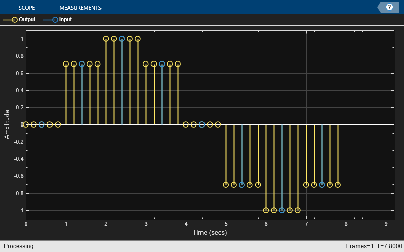
Initialize the timescope object. Update the TimeDisplayOffet property with the output delay of the filter. Visualize the input and output signals on the time scope.
ts = timescope(NumInputPorts=2,SampleRate=[FsOut 1],... TimeDisplayOffset=[0, D],... ChannelNames={"Output","Input"}, ... TimeSpan=length(u)*1.1, ... YLimits=[-1.1,1.1],... PlotType="stem");
ts(y,u)
Design an FIR decimator with the decimation factor of 3 and polyphase length of 28. Use the default stopband attenuation of 80 dB.
b = designMultirateFIR(InterpolationFactor=1,... DecimationFactor=3,... PolyphaseLength=28); impz(b)

Create a dsp.FIRDecimator object by setting the SystemObject flag to true. This design has the OverlapTransition set to true by default. The transition bands therefore overlap.
bSysObjwithOverlap = designMultirateFIR(InterpolationFactor=1,... DecimationFactor=3,... PolyphaseLength=28,SystemObject=true,... Verbose=true)
designMultirateFIR(InterpolationFactor=1, DecimationFactor=3, PolyphaseLength=28, InputSampleRate="normalized", OverlapTransition=true, DesignMethod="kaiser", StopbandAttenuation=80, Datatype="double", SystemObject=true)
bSysObjwithOverlap = dsp.FIRDecimator with properties:
Main DecimationFactor: 3 NumeratorSource: 'Property' Numerator: [0 -3.3618e-05 -5.6028e-05 0 1.2589e-04 1.7681e-04 0 -3.2083e-04 -4.1865e-04 0 6.7942e-04 8.4848e-04 0 -0.0013 -0.0016 0 0.0022 0.0026 0 -0.0036 -0.0043 0 0.0057 0.0066 0 -0.0087 -0.0099 0 0.0130 0.0148 0 -0.0194 … ] (1×84 double) Structure: 'Direct form'
Show all properties
Set the OverlapTransition to false and redesign the FIR decimator.
bSysObjwithNoOverlap = designMultirateFIR(InterpolationFactor=1,... DecimationFactor=3,... PolyphaseLength=28,SystemObject=true,... OverlapTransition=false,Verbose=true)
designMultirateFIR(InterpolationFactor=1, DecimationFactor=3, PolyphaseLength=28, InputSampleRate="normalized", OverlapTransition=false, DesignMethod="kaiser", StopbandAttenuation=80, Datatype="double", SystemObject=true)
bSysObjwithNoOverlap = dsp.FIRDecimator with properties:
Main DecimationFactor: 3 NumeratorSource: 'Property' Numerator: [-1.7738e-05 -2.1857e-05 1.0313e-05 7.8283e-05 1.2681e-04 7.1241e-05 -1.1841e-04 -3.3767e-04 -3.7033e-04 -5.2466e-05 5.1928e-04 9.3352e-04 7.0375e-04 -2.9223e-04 -0.0015 -0.0020 -8.6943e-04 0.0014 0.0034 0.0033 … ] (1×85 double) Structure: 'Direct form'
Show all properties
Visualize the magnitude response of the two designs using freqzmr. The design with overlap shows distortion at higher frequencies.
freqzmr(bSysObjwithOverlap)

The design with no overlap has no aliasing or imaging issues at the higher frequencies.
freqzmr(bSysObjwithNoOverlap)

Design an FIR rate converter with the interpolation factor of 3, decimation factor of 4, polyphase length of 28, and stopband attenuation of 90 dB. Use the Datatype argument to design the filter in single-precision.
L = 3; M = 4; PL = 28; Ast = 90; b = designMultirateFIR(InterpolationFactor=L,... DecimationFactor=M,... PolyphaseLength=PL,... StopbandAttenuation=Ast,... Datatype="single"); impz(b,1)

Design an FIR rate converter with the interpolation factor of 3, decimation factor of 4, normalized transition width of 0.2, and stopband attenuation of 90 dB. Use the like argument to design the filter in single-precision.
TW = 0.2; bTW = designMultirateFIR(InterpolationFactor=L,... DecimationFactor=M,... TransitionWidth=TW,... StopbandAttenuation=Ast,... like=single(M)); impz(bTW,1)

Since R2024b
Design an FIR rate converter using the Kaiser window design method. The design has nonoverlapping transition bands. Compare the design containing a polyphase length of 40 with a design of polyphase length 80.
Use the designMultirateFIR function to design the two rate conversion filters.
- Set
DecimationFactorto 9 - Set
InterpolationFactorto 5 - Set
DesignMethodto"kaiser" - Set
OverlapTransitiontofalse. - Set
PolyphaseLengthto 40 and 80, respectively, for the two filters. - Set
InputSampleRateto 1200 Hz.
rcPoly40 = designMultirateFIR(DecimationFactor=9,... InterpolationFactor=5,OverlapTransition=false,... PolyphaseLength=40,InputSampleRate=1200,... Verbose=true,SystemObject=true)
designMultirateFIR(InterpolationFactor=5, DecimationFactor=9, PolyphaseLength=40, InputSampleRate=1200, OverlapTransition=false, DesignMethod="kaiser", StopbandAttenuation=80, Datatype="double", SystemObject=true)
rcPoly40 = dsp.FIRRateConverter with properties:
Main InterpolationFactor: 5 DecimationFactor: 9 NumeratorSource: 'Property' Numerator: [3.5638e-05 5.0900e-05 6.5026e-05 7.4794e-05 7.6537e-05 6.6569e-05 4.1705e-05 -1.3935e-07 -5.9359e-05 -1.3414e-04 -2.2010e-04 -3.1017e-04 -3.9481e-04 -4.6249e-04 -5.0064e-04 -4.9684e-04 -4.4025e-04 -3.2327e-04 … ] (1×201 double)
Show all properties
rcPoly80 = designMultirateFIR(DecimationFactor=9,... InterpolationFactor=5,OverlapTransition=false,... PolyphaseLength=80,InputSampleRate=1200,... Verbose=true,SystemObject=true)
designMultirateFIR(InterpolationFactor=5, DecimationFactor=9, PolyphaseLength=80, InputSampleRate=1200, OverlapTransition=false, DesignMethod="kaiser", StopbandAttenuation=80, Datatype="double", SystemObject=true)
rcPoly80 = dsp.FIRRateConverter with properties:
Main InterpolationFactor: 5 DecimationFactor: 9 NumeratorSource: 'Property' Numerator: [-1.5627e-05 -2.1798e-05 -2.6892e-05 -2.9819e-05 -2.9550e-05 -2.5283e-05 -1.6599e-05 -3.6000e-06 1.3008e-05 3.1892e-05 5.1155e-05 6.8479e-05 8.1348e-05 8.7337e-05 8.4428e-05 7.1331e-05 4.7765e-05 1.4649e-05 … ] (1×401 double)
Show all properties
Visualize the magnitude response of these two filters. The filter with the longer polyphase length has a narrower transition width. The stopband edge for both filters is exactly 1/max(9,5) or 1/9.
filterAnalyzer(rcPoly40,rcPoly80,FilterNames=["PolyphaseLength40","PolyphaseLength80"])
![]()
Since R2024b
Design FIR rate converter that converts a signal from 44.1 kHz to 48 kHz with a polyphase length of 24. Design the filter with both the Kaiser method and equiripple method. Compare the two designs.
Use the designMultirateFIR function to design the two filters.
- Set
InterpolationFactorto 160. - Set
DecimationFactorto 147. - Set
OverlapTransitiontofalseso that the two filters have nonoverlapping transition bands. - Set
PolyphaseLengthto 24. - Set
DesignMethodto"equiripple"and"kaiser", respectively, for the two filters.
L = 160; M = 147; rcEqui = designMultirateFIR(DecimationFactor=M,... InterpolationFactor=L,OverlapTransition=false,... PolyphaseLength=24, DesignMethod='equiripple',Systemobject=true)
rcEqui = dsp.FIRRateConverter with properties:
Main InterpolationFactor: 160 DecimationFactor: 147 NumeratorSource: 'Property' Numerator: [-0.0081 -1.7231e-04 -1.7393e-04 -1.7543e-04 -1.7679e-04 -1.7802e-04 -1.7911e-04 -1.8005e-04 -1.8085e-04 -1.8151e-04 -1.8201e-04 -1.8235e-04 -1.8254e-04 -1.8257e-04 -1.8243e-04 -1.8213e-04 -1.8166e-04 … ] (1×3840 double)
Show all properties
rcKaiser = designMultirateFIR(DecimationFactor=M,... InterpolationFactor=L, OverlapTransition=false,... PolyphaseLength=24, DesignMethod='kaiser',Systemobject=true)
rcKaiser = dsp.FIRRateConverter with properties:
Main InterpolationFactor: 160 DecimationFactor: 147 NumeratorSource: 'Property' Numerator: [-7.0937e-05 -7.2078e-05 -7.3209e-05 -7.4331e-05 -7.5442e-05 -7.6541e-05 -7.7628e-05 -7.8701e-05 -7.9760e-05 -8.0804e-05 -8.1832e-05 -8.2843e-05 -8.3836e-05 -8.4811e-05 -8.5766e-05 -8.6701e-05 -8.7614e-05 … ] (1×3841 double)
Show all properties
Compare the magnitude response of the two designs. The equiripple design performs slightly better in the transition band at the expense of a nearly negligible passband ripple.
fa = filterAnalyzer(rcEqui,rcKaiser,FilterNames=["Equiripple","Kaiser"]); zoom(fa,"x",[0 0.03])
![]()
Since R2024b
Design a minimum-order FIR decimator from 32 kHz to 1 kHz with a transition width of 0.005. Compare the Kaiser design with the equiripple design.
Use the designMultirateFIR function to design two FIR decimators, one with the Kaiser design and the other with the equiripple design. Set the decimation factor to 32, OverlapTransition to false, and the transition width to 0.005. The interpolation factor is 1 by default.
M = 32; Tw = 0.005; minOrderKaiser = designMultirateFIR(DecimationFactor=M,... OverlapTransition=false,TransitionWidth=Tw,... DesignMethod='kaiser',SystemObject=true,... Verbose=true)
designMultirateFIR(InterpolationFactor=1, DecimationFactor=32, TransitionWidth=0.005, InputSampleRate="normalized", OverlapTransition=false, DesignMethod="kaiser", StopbandAttenuation=80, Datatype="double", SystemObject=true)
minOrderKaiser = dsp.FIRDecimator with properties:
Main DecimationFactor: 32 NumeratorSource: 'Property' Numerator: [3.4905e-07 4.3070e-07 5.1335e-07 5.9619e-07 6.7836e-07 7.5896e-07 8.3709e-07 9.1179e-07 9.8213e-07 1.0471e-06 1.1059e-06 1.1574e-06 1.2009e-06 1.2354e-06 1.2602e-06 1.2744e-06 1.2775e-06 1.2689e-06 1.2479e-06 … ] (1×2009 double) Structure: 'Direct form'
Show all properties
minOrderEquiripple = designMultirateFIR(DecimationFactor=M,... OverlapTransition=false,TransitionWidth=Tw,... DesignMethod='equiripple',SystemObject=true,... Verbose=true)
designMultirateFIR(InterpolationFactor=1, DecimationFactor=32, TransitionWidth=0.005, InputSampleRate="normalized", OverlapTransition=false, DesignMethod="equiripple", StopbandAttenuation=80, PassbandRipple=0.1, Datatype="double", SystemObject=true)
minOrderEquiripple = dsp.FIRDecimator with properties:
Main DecimationFactor: 32 NumeratorSource: 'Property' Numerator: [5.2919e-05 1.1057e-05 1.2117e-05 1.3176e-05 1.4225e-05 1.5254e-05 1.6252e-05 1.7210e-05 1.8113e-05 1.8950e-05 1.9707e-05 2.0371e-05 2.0927e-05 2.1366e-05 2.1675e-05 2.1844e-05 2.1862e-05 2.1719e-05 2.1399e-05 … ] (1×1377 double) Structure: 'Direct form'
Show all properties
Compare the magnitude response of the two designs. The Kaiser design performs better in the transition width compared to the equiripple design.
fa = filterAnalyzer(minOrderKaiser,minOrderEquiripple,... FilterNames=["MinOrderKaiser","MinOrderEquiripple"]); zoom(fa,"x",[0 0.05])
![]()
Name-Value Arguments
Specify optional pairs of arguments asName1=Value1,...,NameN=ValueN, where Name is the argument name and Value is the corresponding value. Name-value arguments must appear after other arguments, but the order of the pairs does not matter.
Example: designMultirateFIR(InterpolationFactor=3,PolyphaseLength=32,SystemObject=true) designs and returns a dsp.FIRInterpolator object with an interpolation factor of 3.
Interpolation factor L, specified as a positive integer. To design a pure decimator, set L to 1.
If you design the filter using PolyphaseLength, the interpolation factor is tunable in the generated code, that is, you can pass the interpolation factor as a runtime variable while generating code.
Data Types: single | double | int8 | int16 | int32 | int64 | uint8 | uint16 | uint32 | uint64
Decimation factor M, specified as a positive integer. To design a pure interpolator, set M to1.
If you design the filter using PolyphaseLength, the decimation factor is tunable in the generated code, that is, you can pass the decimation factor as a runtime variable while generating code.
Data Types: single | double | int8 | int16 | int32 | int64 | uint8 | uint16 | uint32 | uint64
Polyphase length P, specified as one of these:
1–– SetDesignMethodto"lagrange". The function uses the zero-order hold method.2–– The function accepts all the design methods. If you setDesignMethodto"lagrange", then 2 is the default polyphase length and the function uses the linear interpolation method.- Positive even integer > 2 –– Set
DesignMethodto"kaiser"or"equiripple".
The polyphase length is tunable in generated code, that is, you can pass the polyphase length as a runtime variable while generating code.
Data Types: single | double | int8 | int16 | int32 | int64 | uint8 | uint16 | uint32 | uint64
Since R2024b
Control the transition band overlap, specified as one of these values:
true–– The transition band of aliases or images overlap. You can use only the Kaiser-window-based design method or the Lagrange polynomial method.false–– The transition bands do not overlap and this property reduces aliasing at higher frequencies. The stopband edge starts exactly at 1/max(L,M) and the entire transition band is contained completely below the stopband edge frequency. L is the interpolation factor and M is the decimation factor. This option allows you to use the equiripple design.

Data Types: logical
Since R2024b
Design method for the lowpass FIR filter, specified as one of these:
"kaiser"–– Kaiser-window-based design. The function uses this method by default if you setOverlapTransitiontotrue."equiripple"–– Equiripple design method. The function supports this method only when you setOverlapTransitiontofalse."lagrange"–– Lagrange polynomial method. To use this method, set:PolyphaseLengthto 1 (zero-order hold) or 2 (linear interpolation).OverlapTransitiontotrue.
(since R2025a)
When you set DesignMethod to"kaiser" or "equiripple", specifying both the transition width and polyphase length results in an overdetermined design. The function does not support specifying both the values.
For more information on the design methods, see Algorithms.
Data Types: char | string
Transition width, TW, of the multirate FIR filter, specified as one of these:
- Normalized scalar in the range (0,1) when you set
InputSampleRate,FsIn, to"normalized".- When you set
OverlapTransitiontotrue, the value of the transition width must be less than or equal to 2/max(L,M), where L is the interpolation factor and M is the decimation factor. - When you set
OverlapTransitiontofalse, the value of the transition width must be less than or equal to 1/max(L,M).
- When you set
- Positive scalar in Hz when you set
InputSampleRate,FsIn, to a positive scalar in Hz. (since R2025a)- When you set
OverlapTransitiontotrue, the value of the transition width must be less than or equal to_FsIn_×min(1,L/M). - When you set
OverlapTransitiontofalse, the value of the transition width must be less than or equal to_FsIn_×min(1,L/M)/2.
- When you set
Specifying both transition width and polyphase length results in an overdetermined design. The function does not support specifying both the values. When you use the transition width to design the filter, the function determines the polyphase length (and therefore the filter length) iteratively.
If you setDesignMethod to "lagrange", you cannot set this argument. (since R2025a)
Data Types: single | double | int8 | int16 | int32 | int64 | uint8 | uint16 | uint32 | uint64
Since R2025a
Sample rate of the filter input, FsIn, specified as one of these options:
"normalized"when frequency specifications such as the transition width are in the normalized frequency units (0,1). Filter analysis tools such as the filterAnalyzer analyze the filter in normalized frequency units.- Positive scalar when frequency specifications such as the transition width are specified in Hz. Filter analysis tools use this value to analyze the filter.
Data Types: single | double | char | string
Stopband attenuation in dB, specified as a nonnegative real scalar greater than or equal to 0.
The function applies the default stopband attenuation value of 80 dB only when you set the interpolation factor L or the decimation factor M to a value greater than 1.
If you design the filter using PolyphaseLength, the stopband attenuation is tunable in the generated code, that is, you can pass the stopband attenuation as a runtime variable while generating code.
If you setDesignMethod to "lagrange", you cannot set this argument. (since R2025a)
Data Types: single | double | int8 | int16 | int32 | int64 | uint8 | uint16 | uint32 | uint64
Since R2024b
Passband ripple, specified as a positive scalar.
Dependencies
This property applies only when you setDesignMethod to"equiripple".
Data Types: single | double | int8 | int16 | int32 | int64 | uint8 | uint16 | uint32 | uint64
Since R2024b
Data type of the filter coefficients by type name, specified as"double" or"single".
You can use the Dataype or thelike argument to specify the data type of the filter coefficients, but you cannot use both arguments at the same time.
If you specify the data type of the filter coefficients using this argument, the function ignores the data types of the other numeric arguments.
Data Types: char | string
Since R2024b
Data type of the filter coefficients as a prototype, specified as a real floating-point value.
You can use the Dataype or thelike argument to specify the data type of filter coefficients, but you cannot use both arguments at the same time.
If you specify the data type of the filter coefficients using this argument, the function ignores the data types of the other numeric arguments.
Example: B = designMultirateFIR(InterpolationFactor=L,DecimationFactor=M,like=single(M))
Example: M = single(5); B = designMultirateFIR(InterpolationFactor=L,DecimationFactor=M,like=M)
Data Types: single | double
Option to create a multirate filter System object, specified as one of these:
false–– The function returns a vector of multirate FIR filter coefficients.true–– The function returns one of these System objects:- dsp.FIRInterpolator when
L≥ 1 andM= 1 - dsp.FIRDecimator when
L= 1 andM> 1 - dsp.FIRRateConverter when
L> 1 andM> 1
When you set theSystemObjectproperty totrue, the function now factors out the GCD in the rate conversion ratio_L_:M. For example, the function treats an_L_:M ratio of 8:4 as 2:1. With this change, these two function calls have the same output.
designMultirateFIR(InterpolationFactor=12,DecimationFactor=40,...
SystemObject=true)
designMultirateFIR(InterpolationFactor=3,DecimationFactor=10,...
SystemObject=true)
(since R2025a)
- dsp.FIRInterpolator when
Data Types: logical
Option to print the entire function call in MATLAB, specified as one of these:
false–– The function does not print the function call.true–– The function prints the entire function call including the default values of theName=Value arguments that you did not specify when calling the function.
Use this argument to view all the values used by the function to design and implement the filter.
Data Types: logical
Output Arguments
Designed filter, returned as one of these options.
- Multirate FIR filter coefficients –– The function returns a row vector of length N when you set theSystemObject argument to
false.
If both L and M are equal to 1, N = 1.
If L > 1 or M > 1, N={PR+1PR M>L>1 and mod(PL,M)≠ 0 otherwise, where 2_P_ is the polyphase length and R is defined by one of these equations:- R = L if_L_ > 1
- R = M if_L_ = 1.
For more details, see the Algorithms section.
If you specify single-precision values in any of the input arguments, the function outputs single-precision filter coefficients. (since R2024a)
If you specify the data type using the Datatype or thelike argument, the function ignores the data types of the other numeric arguments. (since R2024b)
- Multirate FIR filter object –– The function returns one of these multirate filter System objects when you set the
SystemObjectargument totrue.- dsp.FIRInterpolator when
L> 1 andM= 1. - dsp.FIRDecimator when
L= 1 andM> 1. - dsp.FIRRateConverter when
L> 1 andM> 1.
- dsp.FIRInterpolator when
Data Types: single | double
Algorithms
Set OverlapTransition to true
designMultirateFIR designs an_R_th band Nyquist FIR filter using a Kaiser window vector to window the truncated impulse response of the FIR filter.
The filter length N is defined as
where, P is the polyphase length and R is the number of polyphase branches which is defined by one of these equations:
- R = L if_L_ > 1
- R = M if_L_ = 1.
The function algorithm delays the truncated impulse response_d(n)_ by N/2 samples to make it causal. The truncated and delayed impulse response is
where wc=π/R.
For every _R_th band, the impulse response of the Nyquist filters is exactly zero. Because of this property, when the algorithm uses Nyquist filters for pure interpolation, the input samples remain unaltered after interpolating.
When designing a Nyquist filter, the algorithm uses a Kaiser window because of its near-optimum performance and ability to provide a robust design. The window depends on two parameters: length N + 1 and shape parameter_β_.
The Kaiser window is defined by
where _I_0 is the zeroth-order modified Bessel function of the first kind.
The shape parameter β is calculated using
where Astop is the stopband attenuation in dB.
The windowed impulse response is
h(n) for n = 0,1,…,N/2,…,N are the coefficients of the multirate filter. These coefficients are defined by the interpolation factor_L_ and decimation factor M.
OverlapTransition set tofalse
The function designs a lowpass FIR filter with a non-overlapping transition band.
When you set OverlapTransition tofalse, the adjusted cutoff frequency_ωc_ = 2π_Fc_, where_Fc_ is given by these equations.
When you specify the polyphase length P,
The filter length N is defined as
where, P is the polyphase length and R is defined by one of these equations:
- R = L if_L_ > 1
- R = M if_L_ = 1.
When you specify the target transition width TW,
The estimated filter length is given by,
The function adjusts the filter length until the design meets the filter specifications.
The function designs using the equiripple method only if you setOverlapTransition to false.
When you specify the polyphase length P, the function designs the filter using the firceqrip function.
num = L*firceqrip(N-1,Fst,[Wp Ws],'stopedge')
where,
- L is the interpolation factor
- R = L if_L_ > 1
- R = M if_L_ = 1.
- Fst = 1/max(L,M) is the stopband edge frequency
- Wp is the passband ripple in linear units
- Ws is the stopband attenuation in linear units
When you specify the transition width TW, the function designs the filter using the firpm function. First, the function estimates the minimum order filter which meets the peak ripple using thefirpmord function. Then, the function iteratively calls the firpm function until the measured stopband ripple is less than the target stopband attenuation that you specify.
The "lagrange" method uses Lagrange's polynomial interpolation formula to construct the filter.
The function derives the FIR filter coefficients from Lagrange interpolation polynomials of order 0 (zero-order hold) and 1 (linear interpolation). SetPolyphaseLength to 1 for zero-order hold (ZOH) interpolation, and set PolyphaseLength to 2 for linear interpolation. The function determines the number of polyphase branches based on the rate conversion factors L and M.
This MATLAB code shows how the function designs the filter when you setDesignMethod to "lagrange".
if L>1 R = L; else R = M; end
gain = L/R;
if P==1 % ZOH num = gainones(1,PR); elseif P==2 % Linear num = gaintriang(1,PR-1)'; end
In this code,
- L is the interpolation factor
- M is the decimation factor
- P is the polyphase length
- R is the number of polyphase branches
- num is the vector of filter coefficients
This table shows the filter length N for each combination of conversion factors L and M and the polyphase length P.
| | Number of Polyphase Branches (R) | Filter Length (N) | Gain | | | | ------------------------------------------------ | ------------------- | ---- | ------ | ----- | | ZOH (_P_=1) | Linear (_P_=2) | | | | | L = M | 1 | 1 | 1 | 1 | | L = 1, M > 1 (decimator) | M | M | 2_M_−1 | 1/M | | L > 1 (interpolator or sample-rate converter) | L | L | 2_L_−1 | 1 |
References
[1] Orfanidis, Sophocles J. Introduction to Signal Processing. Upper Saddle River, NJ: Prentice-Hall, 1996.
Extended Capabilities
When you design the filter using the PolyphaseLength argument, and you set the SystemObject argument tofalse, the function supports code generation with no limitations.
When you design the filter using the TransitionWidth argument, the inputs to the function must be constants when generating code.
% Transition width equals 0.1 codegen functionName -args {coder.Constant(13),coder.Constant(5),coder.Constant(0.1),coder.Constant(80)} functionName_mex(13,5,0.1,80)
function [B3] = functionName(L,M,TW,Ast)
B3 = designMultirateFIR(InterpolationFactor=L,...
        DecimationFactor=M,...
        TransitionWidth=TW,...
        StopbandAttenuation=Ast);
end
When you set theSystemObject argument to true, the inputs to the function must be constants when generating code. (since R2024a)
This function supports strict single precision in generated code. If any of the input arguments are in single precision,or you use the Datatype andlike arguments to specify single-precision (since R2024b), the code you generate uses strictly single-precision arithmetic. (since R2024a)
Version History
Introduced in R2016a
You can now specify the input sample rate as a positive scalar in Hz using theInputSampleRate property. The transition width is in Hz and must be a scalar less than or equal toInputSampleRate/2.
When you specify InputSampleRate as a positive scalar in Hz while designing the filter with the designMultirateFIR function, filter analysis tools such as the filterAnalyzer analyze the filter in Hz instead of in normalized frequency units. For an example, see Design Kaiser-Window-Based FIR Rate Converter with Nonoverlapping Transition Bands.
You can now specify the design method as "lagrange" in thedesignMultirateFIR function. The function designs the FIR filter based on Lagrange's polynomial interpolation formula. If you set the polyphase length to 1, the function uses the zero-order hold method, and if you set the polyphase length to 2, the function uses the linear interpolation method.
For more information, see Algorithms.
For an example that uses this design method, see Design FIR Interpolator Using Lagrange Design Method.
When you set the SystemObject flag totrue, the function now factors out the GCD in the rate conversion ratio L:M. For example, the function treats an_L_:M ratio of 8:4 as 2:1. With this change, these two function calls have the same output.
designMultirateFIR(InterpolationFactor=12,DecimationFactor=40,... SystemObject=true) designMultirateFIR(InterpolationFactor=3,DecimationFactor=10,... SystemObject=true)
You can now specify the data type of filter coefficients explicitly using theDatatype and like arguments.
The designMultirateFIR function now supports the equiripple design method and non-overlapping transition bands using the newDesignMethod, OverlapTransition, andPassbandRipple properties.
Starting in R2024a, specifying the arguments using the Value only syntax is discouraged in the designMultirateFIR function.
Existing instances of the function using the Value only arguments continue to run but are discouraged. Instead, specify the arguments using the Name=Value syntax.
Starting in R2024a, the designMultirateFIR function supports specifying the input arguments using the Name=Value syntax.
Here is the table that shows how to replace your existing code.
| Existing code | Replace with |
|---|---|
| designMultirateFIR(L,M) | designMultirateFIR(InterpolationFactor=L,DecimationFactor=M) |
| designMultirateFIR(L,M,HP)HP is half-polyphase length and is a positive integer | designMultirateFIR(InterpolationFactor=L,DecimationFactor=M,PolyphaseLength=2_HP_) |
| designMultirateFIR(L,M,HP,ast)HP is half-polyphase length and is a positive integer. | designMultirateFIR(InterpolationFactor=L,DecimationFactor=M,PolyphaseLength=2_HP_,StopbandAttenuation=ast) |
| designMultirateFIR(L,M,TW)TW is transition width and its value is in the range (0, 1). | designMultirateFIR(InterpolationFactor=L,DecimationFactor=M,TransitionWidth=TW) |
| designMultirateFIR(L,M,TW,ast)TW is transition width and its value is in the range (0, 1). | designMultirateFIR(InterpolationFactor=L,DecimationFactor=M,TransitionWidth=TW,StopbandAttenuation=ast) |
The half-polyphase length P input argument is discouraged in the designMultirateFIR function. Use the new PolyphaseLength argument instead to specify the polyphase length 2_P_.
Existing instances of the function using the half-polyphase length continue to run. But it is recommended that you replace this code to use thePolyphaseLength argument.
Here is the table that shows how to replace your existing code.
| Existing code | Replace with |
|---|---|
| designMultirateFIR(L,M,HP)HP is half-polyphase length and is a positive integer | designMultirateFIR(InterpolationFactor=L,DecimationFactor=M,PolyphaseLength=2_HP_) |
| designMultirateFIR(L,M,HP,ast)HP is half-polyphase length and is a positive integer. | designMultirateFIR(InterpolationFactor=L,DecimationFactor=M,PolyphaseLength=2_HP_,StopbandAttenuation=ast) |
When you specify any of the input arguments in single-precision, thedesignMultirateFIR function designs filter coefficients in single precision both in simulation and in generated code.
The designMultirateFIR function supports code generation when you set the 'SystemObject' flag totrue.
See Also
Functions
- designRateConverter | designLowpassFIR | designHighpassFIR | designHalfbandFIR | firnyquist | rcosdesign | fdesign.decimator | fdesign.interpolator | fdesign.halfband | designMultistageDecimator | designFracDelayFIR