dsp.DigitalDownConverter - Translate digital signal from intermediate frequency (IF) band to baseband and
decimate it - MATLAB ([original](https://in.mathworks.com/help/dsp/ref/dsp.digitaldownconverter-system-object.html)) ([raw](?raw))Translate digital signal from intermediate frequency (IF) band to baseband and decimate it
Description
The dsp.DigitalDownConverter object translates digital signal from intermediate frequency (IF) band to baseband and decimates it.
To digitally downconvert the input signal:
- Create the
dsp.DigitalDownConverterobject and set its properties. - Call the object with arguments, as if it were a function.
To learn more about how System objects work, see What Are System Objects?
This object supports C/C++ code generation and SIMD code generation under certain conditions. For more information, see Code Generation.
Creation
Syntax
Description
`dwnConv` = dsp.DigitalDownConverter returns a digital downconverter (DDC) System object™, dwnConv.
`dwnConv` = dsp.DigitalDownConverter(`Name=Value`) sets properties using one or more name-value arguments. For example, to specify a decimation factor of 50, setDecimationFactor to 50.
Properties
Unless otherwise indicated, properties are nontunable, which means you cannot change their values after calling the object. Objects lock when you call them, and therelease function unlocks them.
If a property is tunable, you can change its value at any time.
For more information on changing property values, seeSystem Design in MATLAB Using System Objects.
Set this property to a positive integer scalar, or to a 1-by-2 or 1-by-3 vector of positive integers.
When you set this property to a scalar, the object automatically chooses the decimation factors for each of the three filtering stages.
When you set this property to a 1-by-2 vector, the object bypasses the third filter stage and sets the decimation factor of the first and second filtering stages to the values in the first and second vector elements respectively. Both elements of theDecimationFactor vector must be greater than one.
When you set this property to a 1-by-3 vector, the i th element of the vector specifies the decimation factor for the _i_th filtering stage. The first and second elements of the DecimationFactor vector must be greater than one, and the third element must be 1 or 2.
Data Types: double
When you set this property to true, the object designs filters with the minimum order that meets the passband ripple, stopband attenuation, passband frequency, and stopband frequency specifications that you set using thePassbandRipple, StopbandAttenuation,Bandwidth, StopbandFrequencySource, andStopbandFrequency properties.
When you set this property to false, the object designs filters with orders that you specify in the NumCICSections,SecondFilterOrder, and ThirdFilterOrder properties. The filter designs meet the passband and stopband frequency specifications that you set using the Bandwidth,StopbandFrequencySource, andStopbandFrequency properties.
Data Types: logical
Number of sections of CIC decimator, specified as a positive integer scalar.
Dependencies
This property applies when you set the MinimumOrderDesign property to false.
Data Types: double
Order of CIC compensation filter stage, specified as a positive integer scalar.
Dependencies
This property applies when you set the MinimumOrderDesign property to false.
Data Types: double
Order of third filter stage, specified as an even positive integer scalar. When you set the DecimationFactor property to a 1-by-2 vector, the object ignores the ThirdFilterOrder property because the third filter stage is bypassed.
Dependencies
This property applies when you set the MinimumOrderDesign property to false.
Data Types: double
Two-sided bandwidth BW of the input signal, specified as a positive integer in Hz or in normalized frequency units (since R2024b). The object sets the passband frequency of the cascade of filters to one-half of the value that you specify in the Bandwidth property. Set the value of this property to less thanSampleRate/DecimationFactor. If you set NormalizedFrequency totrue, set the value of this property to less than 2/DecimationFactor. (since R2024b)
Data Types: double
Specify the source of the stopband frequency as Auto orProperty.
When you set this property to Auto and set:
NormalizedFrequencytofalse–– The object places the cutoff frequency of the cascade filter response at approximately_Fc_ =Fs/(2_M_) Hz, where M is the total decimation factor that you specify in theDecimationFactorproperty. The object computes the stopband frequency as Fstop =Fc + (TW/2).TW is the transition bandwidth of the cascade response computed as 2×(Fc_–_Fp), and the passband frequency Fp equals_BW_/2, where BW is the two-sided bandwidth of the input signal.NormalizedFrequencytotrue–– The object places the cutoff frequency of the cascade filter response at approximately_Fc_ = 1/M, where_M_ is the total decimation factor that you specify in theDecimationFactorproperty. The object computes the stopband frequency as Fstop =Fc + (TW/2).TW is the transition bandwidth of the cascade response computed as 2×(Fc_–_Fp), and the passband frequency Fp equals_BW_/2, where BW is the two-sided bandwidth of the input signal.
When you set this property to Property, you can specify the stopband frequency value using the StopbandFrequency property.
Stopband frequency Fstop, specified as a positive scalar in Hz or in normalized frequency units (since R2024b).
Dependencies
To enable this property, set the StopbandFrequencySource property to Property.
Data Types: double
Passband ripple of cascade response in dB, specified as a positive scalar. When you set the MinimumOrderDesign property to true, the object designs the filters so that the cascade response meets the passband ripple that you specify in the PassbandRipple property.
Dependencies
To enable this property, set the MinimumOrderDesign property to true.
Data Types: double
Stopband attenuation of cascade response in dB, specified as a positive scalar. When you set the MinimumOrderDesign property to true, the object designs the filters so that the cascade response meets the stopband attenuation that you specify in the StopbandAttenuation property.
Dependencies
To enable this property, set the MinimumOrderDesign property to true.
Data Types: double
Type of oscillator, specified as one of these options:
Sine wave–– The object frequency down converts the input signal using a complex exponential obtained from samples of a sinusoidal trigonometric function.NCO–– The object performs frequency down conversion with a complex exponential obtained using a numerically controlled oscillator (NCO).Input port–– The object performs frequency down conversion using the complex oscillator signal,z, that you pass as an input to the object.None–– The mixer stage in the object is not present and the object acts as three stage cascaded decimator.
Center frequency of the input signal Fc, specified as a positive scalar in Hz or in normalized frequency units (since R2024b). The value of center frequency must be less than or equal to half the value of theSampleRate property. The object downconverts the input signal from the passband center frequency you specify in theCenterFrequency property to 0.
Dependencies
To enable this property, set the Oscillator property toSine wave or NCO.
Data Types: double
Number of NCO accumulator bits, specified as a positive integer in the range[1 128].
Dependencies
To enable this property, set the Oscillator property toNCO.
Data Types: double
Number of NCO quantized accumulator bits, specified as an integer in the range[1 128]. The value you specify in this property must be less than the value you specify in the NumAccumulatorBits property.
Dependencies
To enable this property, set the Oscillator property toNCO.
Data Types: double
When you set this property to true, a number of dither bits specified in the NumDitherBits property will be used to apply dither to the NCO signal.
Dependencies
To enable this property, set the Oscillator property toNCO.
Number of NCO dither bits, specified as a positive integer smaller than the number of accumulator bits that you specify in the NumAccumulatorBits property.
Dependencies
To enable this property, set the Oscillator property toNCO and the Dither property totrue.
Data Types: double
Since R2024b
Option to set frequencies in normalized units, specified as one of these values:
true–– The center frequency, stopband frequency, and bandwidth must be in the normalized frequency units (0 to 1).
When you set theNormalizedFrequencyproperty totruewhile creating the object and you do not set the frequency specifications, the object automatically sets the default values to normalized frequency units using the default sample rate of 30 MHz.
ddc = dsp.DigitalDownConverter(NormalizedFrequency=true)
ddc =
dsp.DigitalDownConverter with properties:
DecimationFactor: 100
MinimumOrderDesign: true
Bandwidth: 0.0133
StopbandFrequencySource: "Auto"
PassbandRipple: 0.1000
StopbandAttenuation: 60
Oscillator: "Sine wave"
CenterFrequency: 0.9333
NormalizedFrequency: true
When you set the NormalizedFrequency property totrue after you create the object, you must specify the center frequency, stopband frequency, and bandwidth in normalized units before you run the object algorithm.
ddc = dsp.DigitalDownConverter
ddc =
dsp.DigitalDownConverter with properties:
DecimationFactor: 100
MinimumOrderDesign: true
Bandwidth: 200000
StopbandFrequencySource: "Auto"
PassbandRipple: 0.1000
StopbandAttenuation: 60
Oscillator: "Sine wave"
CenterFrequency: 14000000
NormalizedFrequency: false
SampleRate: 30000000
To specify the normalized frequency values, setNormalizedFrequency totrue and manually convert the frequency values in Hz to the normalized values using the input sample rate in Hz. For example, if the input sample rate_Fs_ is 30 MHz, the corresponding bandwidth value in normalized units is_BW_Hz/(Fs/2), the corresponding center frequency in normalized units is_Fc_Hz/(Fs/2), and the corresponding stopband frequency in normalized units is_Fstop_Hz/(Fs/2).
ddc = dsp.DigitalDownConverter;
ddc.NormalizedFrequency = true;
ddc.Bandwidth = 200000/(30e6/2);
ddc.CenterFrequency = 14e6/(30e6/2)
ddc =
dsp.DigitalDownConverter with properties:
DecimationFactor: 100
MinimumOrderDesign: true
Bandwidth: 0.0133
StopbandFrequencySource: "Auto"
PassbandRipple: 0.1000
StopbandAttenuation: 60
Oscillator: "Sine wave"
CenterFrequency: 0.9333
NormalizedFrequency: true
false–– The bandwidth, stopband frequency, and center frequency values are in Hz. You can specify the input sample rate through theSampleRateproperty.
Data Types: logical
Sample rate of the input signal Fs, specified as a positive scalar value greater than or equal to twice the value of theCenterFrequency property.
Dependencies
To enable this property, setNormalizedFrequency to false. (since R2024b)
Data Types: single | double
Fixed-Point Properties
Specify the data type at the input of the first, second, and third (if it has not been bypassed) filter stages as one of Same as input |Custom. The object casts the data at the input of each filter stage according to the value you set in this property.
Specify the filters input fixed-point type as a scaled numerictype (Fixed-Point Designer) object with a Signedness of Auto.
Dependencies
This property applies when you set the FiltersInputDataType property to Custom.
Specify the data type of output as Same as input |Custom.
Specify the output fixed-point type as a scaled numerictype (Fixed-Point Designer) object with a Signedness of Auto.
Dependencies
This property applies when you set the OutputDataType property to Custom.
Usage
Syntax
Description
[y](#d126e268325) = dwnConv([x](#d126e268176)) takes an input x and outputs a signal, y that is frequency downconverted and downsampled.
[y](#d126e268325) = dwnConv([x](#d126e268176),[z](#d126e268252)) uses the complex input, z, as the oscillator signal used to frequency down convert input x when you set the Oscillator property to Input port.
Input Arguments
Data input, specified as a column vector or a matrix. The length of inputx must be a multiple of the decimation factor. When the data type of x is double orsingle precision, the data type of y is the same as that of x. When the data type of x is of a fixed-point type, the data type of y is defined by theOutputDataType property.
The input can have multiple channels only if its data type isdouble or single. The input can be of data type double, single, signed integer, or signed fixed-point (fi objects).
Data Types: single | double | int8 | int16 | int32 | int64 | fi
Complex Number Support: Yes
Oscillator signal used to frequency down convert the input signal, specified as a column vector or a matrix. This input must be complex. The length ofz must be equal to the length of x.z can be double, single, signed integer, or signed fixed-point (fi objects).
Dependencies
This input applies when you set the Oscillator property toInput port.
Data Types: single | double | int8 | int16 | int32 | int64 | fi
Complex Number Support: Yes
Output Arguments
Down converted and down sampled signal, returned as a column vector or a matrix. The length of y is equal to the length of x divided by the DecimationFactor. When the data type ofx is double or single precision, the data type of y is the same as that ofx. When the data type of x is of a fixed point type, the data type of y is defined by theOutputDataType property.
Data Types: single | double | int8 | int16 | int32 | int64 | fi
Complex Number Support: Yes
Object Functions
To use an object function, specify the System object as the first input argument. For example, to release system resources of a System object named obj, use this syntax:
| getDecimationFactors | Get decimation factors of each filter stage of a digital down converter |
|---|---|
| getFilterOrders | Get orders of digital down converter or digital up converter filter cascade |
| getFilters | Get handles to digital down converter or digital up converter filter cascade objects |
| groupDelay | Group delay of digital down converter or digital up converter filter cascade |
| visualize | Display response of digital down converter or digital up converter filter cascade |
| filterAnalyzer | Analyze filters with Filter Analyzer app |
| step | Run System object algorithm |
|---|---|
| release | Release resources and allow changes to System object property values and input characteristics |
| reset | Reset internal states of System object |
Examples
Create a digital up converter object that up samples a 1 KHz sinusoidal signal by a factor of 20 and up converts it to 50 KHz. Create a digital down converter object that down converts the signal to 0 Hz and down samples it by a factor of 20.
Create a sine wave generator to obtain the 1 KHz sinusoidal signal with a sample rate of 6 KHz.
Fs = 6e3; % Sample rate sine = dsp.SineWave(Frequency=1000,... SampleRate=Fs,... SamplesPerFrame=1024); x = sine(); % generate signal
Create a DigitalUpConverter object. Use minimum order filter designs and set passband ripple to 0.2 dB and the stopband attenuation to 55 dB. Set the double sided signal bandwidth to 2 KHz.
upConv = dsp.DigitalUpConverter(... InterpolationFactor=20,... SampleRate=Fs,... Bandwidth=2e3,... StopbandAttenuation=55,... PassbandRipple=0.2,... CenterFrequency=50e3);
Create a DigitalDownConverter object. Use minimum order filter designs and set the passband ripple to 0.2 dB and the stopband attenuation to 55 dB.
dwnConv = dsp.DigitalDownConverter(... DecimationFactor=20,... SampleRate=Fs*20,... Bandwidth=3e3,... StopbandAttenuation=55,... PassbandRipple=0.2,... CenterFrequency=50e3);
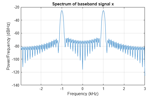
Create a spectrum estimator to visualize the signal spectrum before up converting, after up converting, and after down converting.
window = hamming(floor(length(x)/10)); figure; pwelch(x,window,[],[],Fs,"centered") title("Spectrum of baseband signal x")
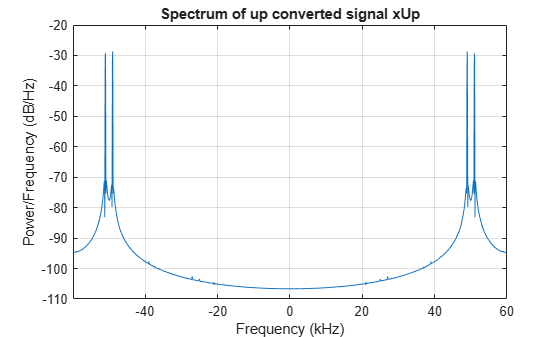
Up convert the signal and visualize the spectrum
xUp = upConv(x); % up convert window = hamming(floor(length(xUp)/10)); figure; pwelch(xUp,window,[],[],20*Fs,"centered"); title("Spectrum of up converted signal xUp")
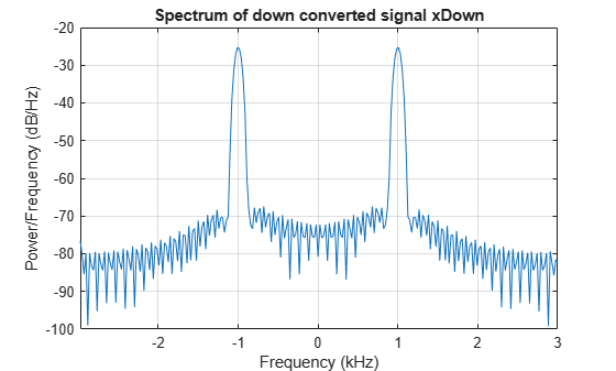
Down convert the signal and visualize the spectrum
xDown = dwnConv(xUp); % down convert window = hamming(floor(length(xDown)/10)); figure; pwelch(xDown,window,[],[],Fs,"centered") title("Spectrum of down converted signal xDown")
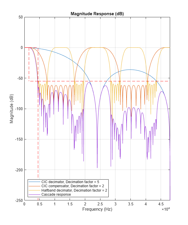
Visualize the response of the decimation filters
Get decimation factors of each filter stage of the dsp.DigitalDownConverter System object™.
Create a dsp.DigitalDownConverter System object with the default settings. Using the getDecimationFactors function, obtain the decimation factors of each stage of the object.
dwnConv = dsp.DigitalDownConverter
dwnConv = dsp.DigitalDownConverter with properties:
       DecimationFactor: 100
     MinimumOrderDesign: true
              Bandwidth: 200000
StopbandFrequencySource: 'Auto'
         PassbandRipple: 0.1000
    StopbandAttenuation: 60
             Oscillator: 'Sine wave'
        CenterFrequency: 14000000
    NormalizedFrequency: false
             SampleRate: 30000000
Show all properties
M = getDecimationFactors(dwnConv) %#ok
The DecimationFactor property of the object is set to 100. The output M is by default a 1-by-3 vector, where each element in the vector is a factor of the overall decimation factor.
When you set the DecimationFactor to a 1-by-2 vector, the object bypasses the third filter stage and sets the decimation factor of the first and second filtering stages to the values in the first and second vector elements respectively.
dwnConv.DecimationFactor = [10 10]
dwnConv = dsp.DigitalDownConverter with properties:
       DecimationFactor: [10 10]
     MinimumOrderDesign: true
              Bandwidth: 200000
StopbandFrequencySource: 'Auto'
         PassbandRipple: 0.1000
    StopbandAttenuation: 60
             Oscillator: 'Sine wave'
        CenterFrequency: 14000000
    NormalizedFrequency: false
             SampleRate: 30000000
Show all properties
M = getDecimationFactors(dwnConv)
The output of the getDecimationFactors function is now a 1-by-2 vector.
More About
The following block diagram represents the DDC arithmetic with signed fixed-point inputs.
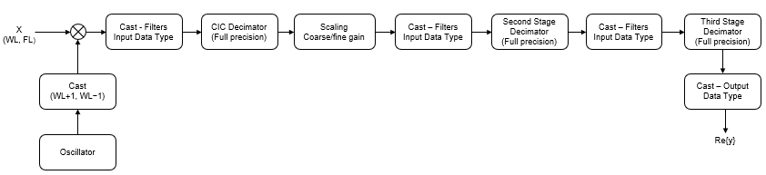
WLis the word length of the input, andFLis the fraction length of the input.- The input of each filter is cast to the filter input data type. In the
dsp.DigitalDownConverterobject, you can specify the filter input data type through theFiltersInputDataTypeandCustomFiltersInputDataTypeproperties. In theDigital Down-Converter block, you can specify the filter input data type through the Stage input parameter. - The oscillator output is cast to a word length equal to the input word length plus one. The fraction length is equal to the input word length minus one.
- The scaling at the output of the CIC decimator consists of coarse- and fine-gain adjustments. The coarse gain is achieved using the reinterpretcast (Fixed-Point Designer) function on the CIC decimator output. The fine gain is achieved using full-precision multiplication.
The following figure depicts the coarse-gain and fine-gain operations.
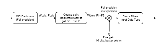
If the normalization gain is G (where 0<G≦1), then:
WLcicis the word length of the CIC decimator output andFLcicis the fraction length of the CIC decimator output.F1 = abs(nextpow2(G)), indicating the part of G achieved using bit shifts (coarse gain).F2= fraction length specified by the filter input data type.fg = fi((2^F1)*G, true, 16), which indicates that the remaining gain cannot be achieved with a bit shift (fine gain).
For a hardware-optimized digital downconverter algorithm that supports HDL code generation, see Implement Digital Downconverter for FPGA (DSP HDL Toolbox). This example uses DSP HDL Toolbox™ blocks that have hardware-friendly valid and reset control signals, and models exact hardware latency behavior. The Simulink® model in the example supports HDL code generation with HDL Coder™ tools.
You can model the same algorithm in MATLAB® by using DSP HDL Toolbox System objects.
Algorithms
The digital down converter downconverts the input signal by multiplying it with a complex exponential that has the specified center frequency. The algorithm downsamples the frequency downconverted signal using a cascade of three decimation filters. In this case, the filter cascade consists of a CIC decimator, a CIC compensator, and a third FIR decimation stage. The following block diagram shows the architecture of the digital down converter.
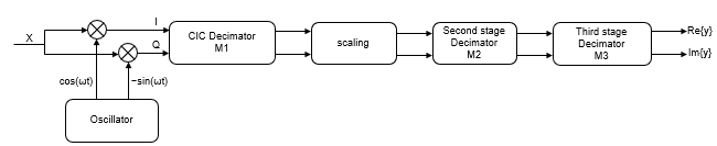
The scaling section normalizes the CIC gain and the oscillator power. It can also contain a correction factor to achieve the desired ripple specification. When you specify an oscillator signal through the input port, the normalization factor does not include the oscillator power factor. Depending on how you set the decimation factor, the block bypasses the third filter stage. When the input data type is double or single, the algorithm implements an _N_-section CIC decimation filter as an FIR filter with a response that corresponds to a cascade of N boxcar filters. The algorithm emulates a CIC filter with an FIR filter so that you can run simulations with floating-point data. When the input data type is fixed-point, the algorithm implements a true CIC filter with actual comb and integrator sections.
This block diagram represents the DDC arithmetic with single or double-precision, floating-point inputs.
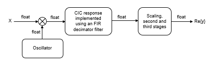
For details about fixed-point operation, see Fixed Point.
Extended Capabilities
Version History
Introduced in R2012a
Starting in R2025a, the Filter Design HDL Coder™ product is discontinued. So, this object no longer supports HDL code generation by using the generatehdl function. For a hardware-optimized digital downconverter algorithm that supports HDL code generation, see Implement Digital Downconverter for FPGA (DSP HDL Toolbox). You can model the same algorithm in MATLAB by using DSP HDL Toolbox System objects.
The visualizeFilterStages function has been renamed tovisualize. Existing instances of this function continue to run. For new instances, use visualize.
The visualize function now launches a MATLAB figure to display the magnitude response of the digital down converter filter cascade.
When you set the NormalizedFrequency property totrue, you must specify the bandwidth, stopband frequency, and the center frequency in normalized frequency units (0 to 1). For more information, see theNormalizedFrequency property description.