Overview of Multirate Filters - MATLAB & Simulink (original) (raw)
Multirate filters are digital filters that change the sample rate of a digital signal, often incorporating FIR or IIR filters to mitigate aliasing or imaging in the rate converted signal. These filters are categorized as decimators that reduce the sample rate, interpolators that increase the sample rate, and rate converters that do a combination of both. DSP System Toolbox™ offers several MATLAB® System objects and Simulink® blocks which implement decimators, interpolators, and rate converters. Advanced filter technologies such as channelizers, channel synthesizers, two-channel halfband filter banks, and multilevel filter banks use these filters as building components.
Decimation and Interpolation
A filter that reduces the input rate is called a decimator. A filter that increases the input rate is called an interpolator. The process of decimation reduces the sample rate by compressing the data, retaining only the desired information. Interpolation, on the other hand, increases the sample rate of the signal. Interpolation is useful, for example, when you need to feed a signal to a system operating at a higher rate. To visualize this process, examine the following figure, which illustrates the processes of interpolation and decimation in the time domain.
If you start with the top signal, sampled at a frequency_Fs_, then the bottom signal is sampled at_Fs_/2 frequency. In this case, the decimation factor_M_ is 2. The process of decimation and interpolation allow sample rate to be decreased or increased while minimizing undesirable effects of errors such aliasing and imaging.
Decimators
Conceptually, the decimator consists of an anti-aliasing lowpass filter followed by a downsampler. The role of the lowpass filter is to bandlimit the input signal before downsampling it, so that the Nyquist sampling theorem is satisfied.
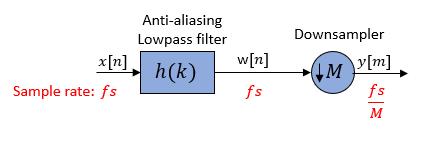
The downsampler reduces the sample rate from fs to_fs_/M. To prevent aliasing at the lower rate of fs/M, the decimator uses a lowpass filter prior to the downsampler. The lowpass filter bandlimits the input signal to less than fs/2_M_. This bandlimiting operation makes sure that the Nyquist criterion for sampling is satisfied, and therefore guarantees near perfect reconstruction of the filtered signal_w_[_n_]. If the Nyquist criterion is not satisfied, aliasing occurs and the signal cannot be perfectly reconstructed.
According to the Nyquist theorem, for bandlimited signals, the sample rate must be at least twice the bandwidth of the signal. For example, if you have a lowpass filter with the highest frequency of 10 MHz, and a sample rate of 60 MHz, the highest frequency that can be handled by the system without aliasing is 60/2 = 30 MHz, which is greater than 10 MHz. You can safely set M = 2 in this case, since (60/2)/2 = 15 MHz, which is still greater than 10 MHz.
For the lowpass filter to be anti-aliasing, the filter must satisfy the following requirements:
- Stopband must contain the frequency range_fs_/2_M_ ≤ f ≤fs/2.
- Passband must be contained in the frequency range 0 ≤f <fs/2_M_.
- To not lose any information in the decimation process, the highest frequency of interest in the original signal fp must be less than fs/2_M_. This condition when not satisfied results in aliasing.
Effect on the Time and Frequency Domain
Consider a decimator with a downsample factor of 3.
Pass the input signal _x_[_n_] through an anti-aliasing lowpass filter to yield_w_[_n_]. The downsampler that follows reduces the filtered data by a factor of 3 by discarding 2 samples for every 3 samples to yield _y_[_m_].
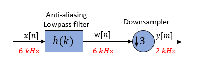
In the frequency domain, the input signal with a sample rate of 6 kHz first passes through the lowpass filter. The lowpass filter bandlimits the signal and removes image frequencies, which would otherwise cause aliasing. The downsampler that follows downsamples the filtered signal by a factor of 3 to a sample rate of 2 kHz.
The spectral components in the dashed lines are the frequencies that would have been aliased if the input signal _x_[_n_] was not bandlimited by the lowpass filter. The spectrum clearly shows the role of lowpass filtering in avoiding aliasing.
![On left is the spectral graph. On right is the time domain graph. First row of graphs correspond to the input signal x[n]. Second row of graphs show the filtered signal w[n] in both the frequency domain and the time domain. Third row of graphs show the downsampled filtered signal y[m]. Fourth row of graphs show the downsampled and unfiltered signal with aliasing.](https://in.mathworks.com/help/dsp/ug/decimation_timefrequencydomain.png)
Interpolators
Conceptually, an interpolator consists of an upsampler followed by an anti-imaging lowpass filter. The role of the lowpass filter is to remove the image frequencies caused by the upsampler.
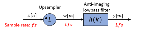
The upsampler inserts L − 1 zero-valued samples to form the new signal w_[m_] at a rate of_Lfs. This rate increase creates image frequencies beyond the Nyquist interval. To remove these image frequencies, pass the_w_[m_] signal through an anti-imaging lowpass filter. The lowpass filter bandlimits the_w_[m_] signal to fs/2 or less. The highest valid frequency after you increase the rate to_Lfs is Lfs/2. To eliminate spectral images, use the lowpass filter to bandlimit the upsampled signal to_Lfs/2_L or fs/2.
Based on these constraints, the lowpass filter must satisfy the following filter requirements:
- Stopband must contain the frequency range fs/2 ≤f ≤ Lfs/2.
- Passband must be contained in the frequency range 0 ≤f < fs/2.
- A gain of L in the passband of the filter to compensate for the amplitude reduction by the interpolation process. Insertion of L − 1 zeros spreads the average energy of each signal sample over L output samples. This effectively attenuates each sample by a factor of L. To compensate for this attenuation, each sample of the output_y_[m_] needs to be multiplied by_L.
Effect on the Time and Frequency Domain
Consider an interpolator with an upsample factor of 3.
Pass the input signal through an upsampler. The upsampler inserts two zero-valued samples to form a new signal_w_[_m_]. Lowpass filter the signal to remove image frequencies created by the rate increase to yield the_y_[_m_] signal.
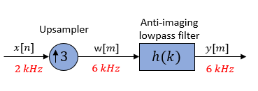
In the frequency domain, pass the input signal with a sample rate of 2 kHz through an upsampler. The sample rate changes to 6 kHz. The lowpass filter that follows bandlimits the signal and removes image frequencies which would otherwise cause aliasing.
The spectral components in the dashed lines are the frequencies removed by the anti-imaging lowpass filter.
![On left are the spectral graphs. On right are the time domain graphs. First row of graphs correspond to the input signal x[n]. Second row of graphs show the upsampled signal w[m] in both the frequency domain and the time domain. Third row of graphs show the anti-imaging filter overlapped with the upsampled signal. Fourth row of graphs show the anti-imaging filtered output.](https://in.mathworks.com/help/dsp/ug/interpolation_timefrequencydomain.png)
For more information about the effects of decimation and interpolation on a sampled signal, see References.
Sample Rate Converters
Sample rate converters change the sample rate of a signal by a noninteger factor,L/M. The sample rate change is achieved by first interpolating the data by L and then decimating by_M_. The interpolation precedes decimation because in that order the overall process is not as lossy.
Conceptually, a sample rate converter can be represented using the following diagram.
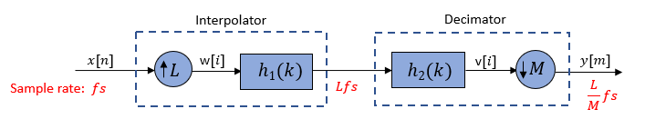
You can combine the two lowpass filters into a single filter since they are in cascade and have a common sample rate. The cascaded filter_h_(k) must be both anti-aliasing and anti-imaging in order to effectively rate convert the signal without introducing significant aliasing and imaging errors. The combined filter has a cutoff frequency of min(fs/2,Lfs/2_M_).

The rate converter resamples the signal according to the values of_L_ and M:
- L < M and_L_/M is not an integer –– Decimation with a noninteger conversion ratio.
- L > M and_L_/M is not an integer –– Interpolation with a noninteger conversion ratio.
- L/M =K/
1, where_K_ is an integer –– Interpolation with an integer conversion ratio. - L/M =
1/K –– Decimation with an integer conversion ratio.
Effect on the Time and Frequency Domain
Consider a sample rate converter with a noninteger conversion factor 3/2.
Pass the input signal through an upsampler. The upsampler inserts two zero-valued samples for each sample of_x_[_n_]. Lowpass filter the signal to yield_v_[_i_]. Then pass the filtered data through a downsampler. The downsampler reduces the signal by a factor of 2 by retaining only one sample for every two samples of_v_[_i_].
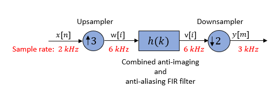
In the frequency domain, the input signal with a sample rate of 2 kHz is first increased by a factor of 3 to 6 kHz. The lowpass filter that follows bandlimits the signal and removes image frequencies which would otherwise cause aliasing. The filtered signal is then downsampled by a factor of 2 to 3 kHz.
The spectral components in the dashed lines are the frequencies which are removed by the lowpass filter.
![On left is the spectral graph. On right is the time domain graph. First row of graphs correspond to the input signal x[n]. Second row of graphs show the upsampled signal w[i] in both the frequency domain and the time domain. Third row of graphs show the filtered upsampled signal v[i]. Fourth row of graphs show the signal after it is downsampled again.](https://in.mathworks.com/help/dsp/ug/rateconversion_timefrequencydomain.png)
When the sample rate conversion ratio is large, it is more efficient to implement the rate converter in two or more stages rather than in a single stage. For more details, see Multistage Rate Conversion.
Reducible Multirate Filters
A multirate filter is said to be reducible if you can modify it through noble identities to produce a single-rate FIR or IIR filter. The equivalent filter has a single FIR or IIR filter stage. Reducible multirate filters are useful because you can characterize and analyze them by their single-stage FIR or IIR equivalent. Therefore, you can call standard analysis functions such asfreqz, impz, and grpdelay on reducible multirate filters.
Consider this filter that is a cascade of an FIR rate converter and an FIR decimator.
redFilt = cascade(dsp.FIRRateConverter(11,3),dsp.FIRDecimator(7))
Here is a conceptual diagram. The filter contains two stages.

redFilt = dsp.FilterCascade with properties:
     Stage1: [1×1 dsp.FIRRateConverter]
     Stage2: [1×1 dsp.FIRDecimator]
CloneStages: true
Applying noble identity for decimation.

Replacing the two filters h_1(k) and_h_2(3_k) with an equivalent filter h(k). The equivalent filter object is dsp.FIRRateConverter(11,21,num) withnum = conv(h1.Numerator, upsample(h2.Numerator,3)).
Alternatively, you can call tf(redFilt) to obtain the transfer function of the equivalent reduced filter.

Irreducible Multirate Filters
Irreducible multirate filters do not have an equivalent FIR or IIR rate conversion filter, that is, they are not reducible.
As an example, consider a cascade of an FIR decimator and an FIR interpolator.
irredFilt = cascade(dsp.FIRDecimator(2),dsp.FIRInterpolator(2))
Here is a diagrammatic representation of the filter. This filter contains two stages. However, you cannot apply noble identities on this filter to reduce it. The filter is therefore irreducible. To analyze irreducible filters in the frequency domain, use the freqzmr function.

References
[1] Fliege, Norbert. Multirate Digital Signal Processing: Multirate Systems, Filter Banks, Wavelets. Wiley, 1994.
[2] Harris, Fred. Multirate Signal Processing for Communication Systems. Prentice Hall PTR, 2004.
[3] Hogenauer, E. “An Economical Class of Digital Filters for Decimation and Interpolation.” IEEE Transactions on Acoustics, Speech, and Signal Processing, vol. 29, no. 2, Apr. 1981, pp. 155–62.
[4] Lyons, Richard G.Understanding Digital Signal Processing. 2nd ed, Prentice Hall PIR, 2004.
[5] Mitra, S.K.Digital Signal Processing, McGraw-Hill, 1998.
[6] Orfanidis, Sophocles J.Introduction to Signal Processing. Prentice Hall, 1996.