External Mode Simulation with TCP/IP or Serial Communication - MATLAB & Simulink (original) (raw)
Set up and run an external mode simulation that uses a TCP/IP or serial (RS-232) communication channel.
- Create and configure a simple model.
- Build the target executable file.
- Run the target application.
- Tune parameters.
The example, which uses the GRT target, does not require external hardware. The generated executable file runs:
- On the development computer that hosts Simulink® and Simulink Coder™.
- As a separate process from MATLAB® and Simulink.
Create and Configure Model
In this part of the example, you create a simple model,ex_extModeExample. You also create a folder calledext_mode_example to store the model and the generated executable.
To create the folder and the model:
- From the MATLAB command line, type:
- Make
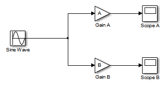
ext_mode_exampleyour working folder: - Create a model in Simulink with a Sine Wave block for the input signal, twoGain blocks in parallel, and two Scope blocks. Be sure to label the Gain and Scope blocks as shown.
- Define and assign two MATLAB workspace variables,
AandB: - Open Gain block A and set its Gain parameter to the variable
A.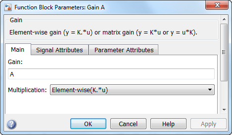
- Open Gain block B and set its Gain parameter to the variable
B.
When the target application is built and connected to Simulink in external mode, you can download new gain values to the executing target application. To do this, you can assign new values to workspace variablesAandB, or edit the values in the block parameters dialog box. For more information, see Tune Parameters. - Verify operation of the model. Open the Scope blocks and run the model. When
A = 2andB = 3, the output appears as shown.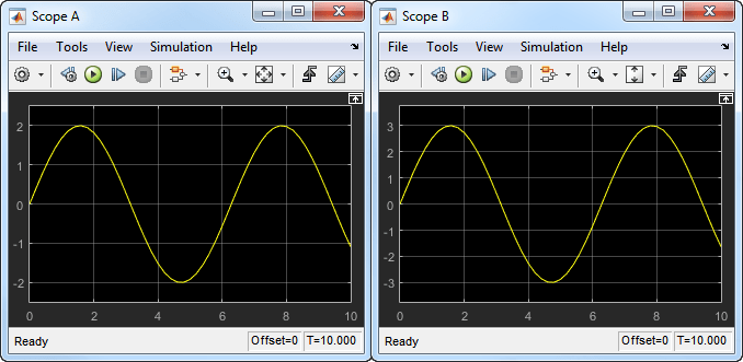
- Save the model as
ex_extModeExample.
Build Target Executable
Set up the model and code generation parameters required for an external mode target application. Then, generate code and build the target application.
- From the Apps tab on the Simulink toolstrip, in the Setup to Run on Hardware section, click Run on Custom Hardware.
- In the Hardware section of the Hardware tab, in the System Target File Description list, select
Generic Real-Time Target (grt.tlc). - In the Prepare section, click Hardware Settings. The Configuration Parameters dialog box opens, displayingHardware Implementation settings that are determined by the system target file.
- On the pane:
- In the Type field, select
Fixed-step. - In the Solver field, select
discrete (no continuous states). - Click Solver details. In theFixed-step size field, specify
0.1. (Otherwise, when you generate code, the Simulink Coder build process produces a warning and supplies a value.) - Click Apply.
- In the Type field, select
- On the Data Import/Export pane, clear theTime and Output check boxes. In this example, data is not logged to the workspace or to a MAT-file. ClickApply.
- On the > pane, check that Default parameter behavior is set to
Tunable. If you make a change, clickApply. - On the > pane, in the Data exchange interface section, selectExternal mode.
- In the External mode configuration section, make sure that the default value
tcpipis selected for theTransport layer parameter.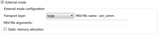
External mode supports communication via TCP/IP, serial, and custom transport protocols. The MEX-file name specifies the name of a MEX-file that implements host-target communication. The default for TCP/IP isext_comm, a MEX-file provided with the Simulink Coder software. You can override this default by supplying other files. If you need to support other transport layers, see Create a Transport Layer for TCP/IP or Serial External Mode Communication.
The MEX-file arguments field lets you specify arguments, such as a TCP/IP server port number, to be passed to the external interface program. These arguments are specific to the external interface that you are using. For information on setting these arguments, see MEX-File Optional Arguments for TCP/IP Transport and MEX-File Optional Arguments for Serial Transport.
This example uses the default arguments. Leave the MEX-file arguments field blank.
The Static memory allocation check box controls how memory is allocated for external mode communication buffers in the target. For this example, do not select the check box. For more information, see Control Memory Allocation for Communication Buffers in Target. - Click Apply to save the external mode settings.
- Save the model.
- Select the Code Generation pane. Make sure that is cleared.
- To generate code and create the target application, in the model window, pressCtrl+B. Or, on the Hardware tab, in theRun on Hardware section, click Monitor & Tune. Then, under Step By Step Commands, clickBuild for Monitoring.
The software creates theex_extModeExampleexecutable file in your working folder.
Run Target Application
You now run the ex_extModeExample target executable and use Simulink as an interactive front end to the running target application. The executable file is in your working folder. Run the target application and establish communication between Simulink and the target.
Note
An external mode program like ex_extModeExample is a host-based executable. Its execution is not tied to a real-time operating system (RTOS) or a periodic timer interrupt, and it does not run in real time. The program just runs as fast as possible, and the time units it counts off are simulated time units that do not correspond to time in the world outside the program.
To run the target application:
- On the Hardware tab, in the Run on Hardware section:
- In the Stop Time field, specify
inf, which makes the model run until the target application receives a stop message from Simulink - Click Monitor & Tune. Then, under Step By Step Commands, click Deploy.
The target application begins execution, and enters a wait state.
- In the Stop Time field, specify
- Open the Scope blocks in the model. Signals are not visible on the scopes until you begin model execution.
- On the Hardware tab, in the Run on Hardware section, click Monitor & Tune. Then, under Step By Step Commands, click Connect. This action initiates a handshake between Simulink and the target application. When Simulink and the target are connected, the Connect button changes to Disconnect.
- In the Run on Hardware section, click
 , which starts execution of the generated model code. The two scopes in your model display the outputs of Gain blocks A and B.
You have established communication between Simulink and the running target application. You can now tune block parameters in Simulink and observe the effects of parameter changes.
Tune Parameters
This table describes how you can tune tunable block parameters during a simulation.
| Approach | Details |
|---|---|
| Model Data Editor | To tune parameters through the Model Data Editor: On the Hardware tab of the Simulink Editor, in the Prepare section, clickTune Parameters, which opens the Model Data Editor.If you want to update multiple tunable parameters simultaneously, in the Prepare section, toggle on Hold Updates.On the Parameters tab of the Model Data Editor, in theValue column, specify new values for your tunable parameters.Toggle off Hold Updates or clickUpdate All Parameters (Ctrl+D). Simulink downloads the new values to the target application simultaneously. If Hold Updates is off, then immediately after you specify a new value, Simulink downloads the new value to the target application.For more information, see Model Data Editor. |
| Block Parameter dialog box | To tune parameters through the Block Parameter dialog box: For each block that you want to update: Double-click the block, which opens the Block Parameter dialog box.In the parameter fields, specify new parameter values.Click Apply or OK.If Hold Updates is on, toggle offHold Updates or click Update All Parameters (Ctrl+D). Simulink downloads the new values to the target application simultaneously. If Hold Updates is off, then immediately after you click Apply orOK, Simulink downloads the new block values to the target application. |
| MATLAB workspace | If block parameters are MATLAB workspace variables: In the Command Window, assign new values to the variables.On the Hardware tab of the Simulink Editor, in the Prepare section, clickUpdate All Parameters (Ctrl+D). Simulink downloads the new values to the target application.For more information, see Create and Edit Variables. |
You cannot change the sample time of the Sine Wave block during simulation. Block sample times are part of the structural definition of the model and are part of the generated code. Therefore, if you want to change a block sample time, you must stop the external mode simulation, reset the sample time of the block, and rebuild the executable.
Block parameter tunability during external mode simulation depends on the way that the generated code represents block parameters.
For example, in the Gain A block dialog box, you cannot change the expression A in the Gain parameter during simulation. Instead, you must change the value of the variable A in the base workspace. You cannot change the expression because the generated code does not allocate storage in memory for the Gain parameter. Instead, the code creates a field A in a structure:
/* Parameters (auto storage) / struct P_ex_extModeExample_T_ { real_T A; / Variable: A / real_T B; / Variable: B / real_T SineWave_Amp; / Expression: 1 / real_T SineWave_Bias; / Expression: 0 / real_T SineWave_Freq; / Expression: 1 / real_T SineWave_Phase; / Expression: 0 */ };
The generated code algorithm uses that field in the code that represents the blockGain A. In this case, the global structure variableex_extModeExample_P uses the typeP_ex_extModeExample_T_:
ex_extModeExample_B.GainA = ex_extModeExample_P.A * rtb_SineWave;
When you change the value of A in the base workspace, the simulation downloads the new value to the field A in the target application.
You can change the expressions in the Sine Wave block parameters during simulation because the generated code creates a field in the global structureex_extModeExample_P to represent each parameter in the block. When you change an expression in the block dialog box, the simulation first evaluates the new expression. The simulation then downloads the resulting numeric value to the corresponding structure field in the target application.
See Create Tunable Calibration Parameter in the Generated Code.
Stop Target Application
To simultaneously disconnect Simulink from the host/target communication and end execution of the target application, on the Hardware tab, in the Run on Hardware section, click Stop.
Control Memory Allocation for Communication Buffers in Target
If you select the > > check box (for GRT and ERT targets), the code generator produces code for external mode that uses only static memory allocation (“malloc-free” code). Selecting Static memory allocation enables the Static memory buffer size parameter. Use this parameter to specify the size of the external mode static memory buffer. The default value is 1,000,000 bytes. If you enter too small a value for your program, the external mode simulation issues an out-of-memory error when it tries to allocate more memory than specified. In such cases, increase the value in theStatic memory buffer size field and regenerate the code.
To determine how much memory to allocate, enable verbose mode on the target (by including OPTS="-DVERBOSE" on the make command line). As it executes, external mode displays the amount of memory it tries to allocate and the amount of memory available to it each time it attempts an allocation. If an allocation fails, you can use this console log to determine the required value for the Static memory buffer size field.
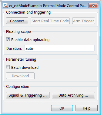
TCP/IP or Serial External Mode Control Panel
The External Mode Control Panel provides controls for TCP/IP or serial external mode operations, including:
- Connect, Start, and Stop
- Upload Target Application Signal Data to Host
- Download Parameters to Target Application
- Configure Host Monitoring of Target Application Signal Data
- Configure Host Archiving of Target Application Signal Data
To open the External Mode Control Panel dialog box, on the Hardware tab, in the Prepare section, click Control Panel.
Connect, Start, and Stop
The External Mode Control Panel performs the same connect/disconnect and start/stop functions found on the Hardware tab on the Simulink toolstrip (see Summary of Graphical Controls for TCP/IP or Serial External Mode Simulation).
Clicking the Connect button connects your model to a waiting or running target application. While you are connected, the button changes to aDisconnect button. Disconnect disconnects your model from the target environment, but does not halt real-time code running in the target environment.
Clicking the Start Real-Time Code button commands the target to start running real-time code. While real-time code is running in the target environment, the button changes to a Stop Real-Time Code button. Stop Real-Time Code stops target application execution and disconnects your model from the target environment.
Upload Target Application Signal Data to Host
The External Mode Control Panel allows you to trigger and cancel data uploads to the host. The destination for the uploaded data can be a scope block, Display block, To Workspace block, or another block or subsystem listed in Blocks and Subsystems Compatible with External Mode.
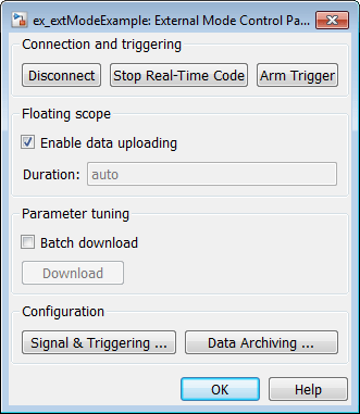
The Arm Trigger and Cancel Trigger buttons provide manual control of data uploading to compatible blocks or subsystems, except floating scopes. (For floating scopes, use the Floating scope section of the External Mode Control Panel.)
- To trigger data uploading to compatible blocks or subsystems, click theArm Trigger button. The button changes to Cancel Trigger.
- To cancel data uploading, click the Cancel Trigger button. The button reverts to Arm Trigger.
You can trigger data uploads manually or automatically. To configure signals and triggers for data uploads, see Configure Host Monitoring of Target Application Signal Data.
A subset of external mode compatible blocks, including Scope, Time Scope, and To Workspace, allow you to log uploaded data to disk. To configure data archiving, see Configure Host Archiving of Target Application Signal Data.
The Floating scope section of the External Mode Control Panel controls when and for how long data is uploaded to Floating Scope blocks. When used in external mode, floating scopes:
- Do not appear in the External Signal & Triggering dialog box.
- Do not log data to external mode archiving.
- Support manual triggering only.
The Floating scope section contains the following parameters:
- Enable data uploading option, which functions as anArm Trigger button for floating scopes. When the target is disconnected, the option controls whether to arm the trigger when connecting the floating scopes. When the target is connected, the option acts as a toggle button to arm or cancel the trigger.
- To trigger data uploading to floating scopes, select Enable data uploading.
- To cancel data uploading to floating scopes, clear Enable data uploading.
- Duration edit field, which specifies the number of base-rate steps for which external mode logs floating scopes data after a trigger event. By default, it is set to
auto, which causes the duration value set in the External Signal & Triggering dialog box to be used. The default duration value is 1000 base rate steps.
Download Parameters to Target Application
The Batch download option on the External Mode Control Panel enables or disables batch parameter changes.
By default, batch download is disabled. If batch download is disabled, when you clickOK or Apply, changes made directly to block parameters by editing block parameter dialog boxes are sent to the target. When you perform an Update Diagram, changes to MATLAB workspace variables are sent.
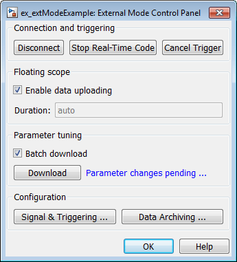
If you select Batch download, the Download button is enabled. Until you click Download, changes made to block parameters are stored locally. When you click Download, the changes are sent in a single transmission.
When parameter changes are awaiting batch download, the External Mode Control Panel displays the message Parameter changes pending... to the right of theDownload button. This message remains visible until the Simulink engine receives notification that the new parameters have been installed in the parameter vector of the target system.
The next figure shows the External Mode Control Panel with the Batch download option activated and parameter changes pending.
Configure Host Monitoring of Target Application Signal Data
- Role of Trigger in Signal Data Uploading
- Configure Signal Data Uploading
- Default Trigger Options
- Select Signals to Upload
- Configure Trigger Options
- Select Trigger Signal
- Set Trigger Conditions
- Modify Signal and Triggering Options While Connected
Role of Trigger in Signal Data Uploading
In external mode, uploading target application signal data to the host depends on a_trigger_. The trigger is a set of conditions that must be met for data uploading to begin. The trigger can be armed or not armed.
- When the trigger is armed, the software checks for the trigger conditions that allow data uploading to begin.
- If the trigger is not armed, the software does not check for the trigger conditions and data uploading cannot begin.
- The trigger can be armed automatically, when the host connects to the target, or manually, by clicking the Arm Trigger button on the External Mode Control Panel.
When the trigger is armed and the trigger conditions are met, the trigger fires and data uploading begins.
When data has been collected for a defined duration, the trigger event completes and data uploading stops. The trigger can then rearm, or remain unarmed until you click theArm Trigger button.
To select the target application signals to upload and configure how uploads are triggered, see Configure Signal Data Uploading.
Configure Signal Data Uploading
Clicking the Signal & Triggering button of the External Mode Control Panel opens the External Signal & Triggering dialog box.
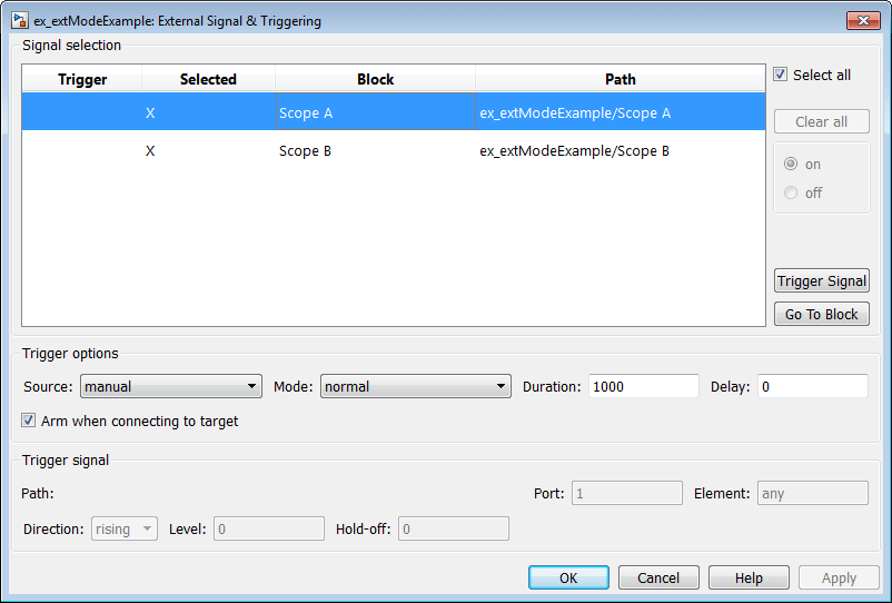
The External Signal & Triggering dialog box displays a list of blocks and subsystems in your model that support external mode signal uploading. For information on which types of blocks are external mode compatible, see Blocks and Subsystems Compatible with External Mode.
In the External Signal & Triggering dialog box, you can select the signals that are collected from the target system and viewed in external mode. You can also select a trigger signal, which triggers uploading of data based on meeting certain signal conditions, and define the triggering conditions.
Default Trigger Options
The preceding figure shows the default settings of the External Signal & Triggering dialog box. The default operation of the External Signal & Triggering dialog box simplifies monitoring the target application. If you use the default settings, you do not need to preconfigure signals and triggers. You start the target application and connect the Simulink engine to it. External mode compatible blocks are selected and the trigger is armed. Signal uploading begins immediately upon connection to the target application.
The default configuration of trigger options is:
Select all: onSource: manualMode: normalDuration: 1000Delay: 0Arm when connecting to target: on
Select Signals to Upload
External mode compatible blocks in your model appear in the Signal selection list of the External Signal & Triggering dialog box. You use this list to select signals that you want to view. In the Selected column, an X appears for each selected block.
The Select all check box selects all signals. By default, Select all is selected.
If Select all is cleared, you can select or clear individual signals using the on andoff options. To select a signal, click its list entry and select the on option. To clear a signal, click its list entry and select theoff option.
The Clear all button clears all signals.
Configure Trigger Options
As described in Role of Trigger in Signal Data Uploading, signal data uploading depends on a trigger. The trigger defines conditions that must be met for uploading to begin. Also, the trigger must be armed for data uploading to begin. When the trigger is armed and trigger conditions are met, the trigger fires and uploading begins. When data has been collected for a defined duration, the trigger event completes and data uploading stops.
To control when and how signal data is collected (uploaded) from the target system, configure the following Trigger options in the External Signal & Triggering dialog box.
- Source:
manualorsignal. Controls whether a button or a signal triggers data uploading.
Selectingmanualdirects external mode to use theArm Trigger button on the External Mode Control Panel as the trigger to start uploading data. When you click Arm Trigger, data uploading begins.
Selectingsignaldirects external mode to use a trigger signal as the trigger to start uploading data. When the trigger signal satisfies trigger conditions (that is, the signal crosses the trigger level in the specified direction), a trigger event occurs. (Specify trigger conditions in the Trigger signal section.) If the trigger is_armed_, external mode monitors for the occurrence of a trigger event. When a trigger event occurs, data uploading begins. - Mode:
normalorone-shot. Controls whether the trigger rearms after a trigger event completes.
Innormalmode, external mode automatically rearms the trigger after each trigger event. The next data upload begins when the trigger fires.
Inone-shotmode, external mode collects only one buffer of data each time you arm the trigger.
For more information on the Mode setting, see Configure Host Archiving of Target Application Signal Data. - Duration: Specifies the number of base rate steps for which external mode uploads data after a trigger event (default is 1000). For example, ifDuration is set to 1000, and the base (fastest) rate of the model is one second:
- For a signal sampled at the base rate, one second (1.0 Hz), external mode collects 1000 contiguous samples during a trigger event.
- For a signal sampled at two seconds (0.5 Hz), external mode collects 500 samples during a trigger event.
- Delay: Specifies a delay to be applied to data collection. The delay represents the amount of time that elapses between a trigger event and the start of data collection. The delay is expressed in base rate steps. It can be positive or negative (default is 0). A negative delay corresponds to pretriggering. When the delay is negative, data from the time preceding the trigger event is collected and uploaded.
- Arm when connecting to target: Selected or cleared. Whether a button or a signal triggers data uploading (as defined bySource), the trigger must be armed to allow data uploading to begin.
If you select this option, connecting to the target arms the trigger.- If the trigger Source is
manual, data uploading begins immediately. - If the trigger Source is
signal, monitoring of the trigger signal begins immediately. Data uploading begins when the trigger signal satisfies trigger conditions (as defined in the Trigger signal section).
If you clear Arm when connecting to target, manually arm the trigger by clicking the Arm Trigger button on the External Mode Control Panel.
- If the trigger Source is
When simulating in external mode, each rate in the model creates a buffer on the target. Each entry in the buffer is big enough to hold all of the data required of every signal in that rate for one time step (time plus data plus external mode indices identifying the signal). The number of entries in the circular buffer is determined by the external mode triggerDuration parameter (ExtModeTrigDuration). The memory allocated on the target for buffering signals is proportional to theDuration and the number of signals uploading. TheDuration also provides an indication of the number of base rate steps with log data after a trigger event in external mode.
The Duration value specifies the number of contiguous points of data to be collected in each buffer of data. You should enter aDuration value equal to the number of continuous sample points that you need to collect rather than relying on a series of buffers to be continuous. If you enter a value less than the total number of sample points, you may lose sample points during the time spent transferring values from the data buffer to the MATLAB workspace. The Simulink software maintains point continuity only within one buffer. Between buffers, because of transfer time, some samples may be omitted.
The Duration value can affect the Limit data points to last value of Scope andTo Workspace blocks. The number of sample points that the blocks save to the MATLAB workspace is the smaller of the two values. To set the number of sample points that the blocks save, clear Limit data points to last. Then, use Duration to specify the number of sample points saved.
Select Trigger Signal
You can designate one signal as a trigger signal. To select a trigger signal, from theSource menu in the Trigger options section, select signal. This action enables the parameters in theTrigger signal section. Then, select a signal in theSignal selection list, and click the Trigger Signal button.
When you select a signal to be a trigger, a T appears in theTrigger column of the Signal selection list. In the next figure, the Scope A signal is the trigger. Scope B is also selected for viewing, as indicated by the X in the Selected column.

After selecting the trigger signal, you can use the Trigger signal section to define the trigger conditions and set the trigger signalPort and Element parameters.
Set Trigger Conditions
Use the Trigger signal section of the External Signal & Triggering dialog box to set trigger conditions and attributes. Trigger signal parameters are enabled only when the trigger parameter Source is set to signal in the Trigger options section.
By default, any element of the first input port of a specified trigger block can cause the trigger to fire (that is, Port 1, any element). You can modify this behavior by adjusting thePort and Element values in theTrigger signal section. The Port field accepts a number or the keyword last. The Element field accepts a number or the keywords any orlast.
In the Trigger signal section, you also define the conditions under which a trigger event occurs.
- Direction:
rising,falling, oreither. The direction in which the signal must be traveling when it crosses the threshold value. The default isrising. - Level: A value indicating the threshold the signal must cross in a designated direction to fire the trigger. By default, the level is 0.
- Hold-off: Applies only to
normalmode. Expressed in base rate steps, Hold-off is the time between the termination of one trigger event and the rearming of the trigger.
Modify Signal and Triggering Options While Connected
After you configure signal data uploading, and connect Simulink to a running target executable, you can modify signal and triggering options without disconnecting from the target.
If the trigger is armed (for example, if the trigger option Arm when connecting to the target is selected, which is the default), the External Signal & Triggering dialog box cannot be modified. To modify signal and triggering options:
- Open the External Mode Control Panel.
- Click Cancel Trigger. Triggering and display of uploaded data stops.
- Open the External Signal & Triggering dialog box and modify signal and trigger options as required. For example, in the Signal selection section, you can enable or disable a scope, and in the Trigger options section, change the trigger Mode, for example, from
normaltoone-shot. - Click Arm Trigger. Triggering and display of uploaded data resumes, with your modifications.
Configure Host Archiving of Target Application Signal Data
In external mode, you can use the Simulink Scope and To Workspace blocks to archive data to disk.
To understand how the archiving features work, consider the handling of data when archiving is not enabled. There are two cases, one-shot mode and normal mode.
- In one-shot mode, after a trigger event occurs, each selected block writes its data to the workspace, as it would at the end of a simulation. If another one-shot is triggered, the existing workspace data is overwritten.
- In normal mode, external mode automatically rearms the trigger after each trigger event. Consequently, you can think of normal mode as a series of one-shots. Each one-shot in this series, except for the last, is referred to as an_intermediate result_. Because the trigger can fire at any time, writing intermediate results to the workspace can result in unpredictable overwriting of the workspace variables. For this reason, the default behavior is to write only the results from the final one-shot to the workspace. The intermediate results are discarded. If you know that enough time exists between triggers for inspection of the intermediate results, you can override the default behavior by selecting the Write intermediate results to workspace option. This option does not protect the workspace data from being overwritten by subsequent triggers.
If you use a Simulink Scope block to archive data to disk, open the Scope parameters dialog box and select the option Log data to workspace. The option is required for these reasons:
- The data is first transferred from the scope data buffer to the MATLAB workspace, before being written to a MAT-file.
- The Variable name entered in the Scope parameters dialog box is the same as the one in the MATLAB workspace and the MAT-file. Enabling the data to be saved enables a variable named with the Variable name parameter to be saved to a MAT-file.
Note
If you do not select the Scope block option Log data to workspace, the MAT-files for data logging are created, but they are empty.
The Enable Data Archiving dialog box supports:
- Folder notes
- File notes
- Automated data archiving
On the External Mode Control Panel, click the Data Archiving button to open the Enable Data Archiving dialog box. If your model is connected to the target environment, disconnect it while you configure data archiving. To enable the other controls in the dialog box, select Enable archiving.
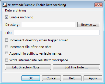
These operations are supported by the Enable Data Archiving dialog box.
Folder Notes
To add annotations for a collection of related data files in a folder, in the Enable Data Archiving dialog box, click Edit Directory Note. The MATLAB editor opens. Place comments that you want saved to a file in the specified folder in this window. By default, the comments are saved to the folder last written to by data archiving.
File Notes
To add annotations for an individual data file, in the Enable Data Archiving dialog box, click Edit File Note. A file finder window opens, which by default is set to the last file to which you have written. Selecting a MAT-file opens an edit window. In this window, add or edit comments that you want saved with your individual MAT-file.
Automated Data Archiving
To configure automatic writing of logging results to disk, optionally including intermediate results, use the Enable archiving option and the controls it enables. The dialog box provides the following related controls:
- Directory: Specifies the folder in which data is saved. If you select Increment directory when trigger armed, external mode appends a suffix.
- File: Specifies the name of the file in which data is saved. If you select Increment file after one-shot, external mode appends a suffix.
- Increment directory when trigger armed: Each time that you click the Arm Trigger button, external mode uses a different folder for writing log files. The folders are named incrementally, for example,
dirname1,dirname2, and so on. - Increment file after one-shot: New data buffers are saved in incremental files:
filename1,filename2, and so on. File incrementing happens automatically in normal mode. - Append file suffix to variable names: Whenever external mode increments file names, each file contains variables with identical names. SelectingAppend file suffix to variable name results in each file containing unique variable names. For example, external mode saves a variable named
xdatain incremental files (file_1,file_2, and so on) asxdata_1,xdata_2, and so on. This approach supports loading the MAT-files into the workspace and comparing variables at the MATLAB command prompt. Without the unique names, each instance ofxdatawould overwrite the previous one in the MATLAB workspace. - Write intermediate results to workspace: If you want theSimulink Coder software to write intermediate results to the workspace, select this option.
Summary of Graphical Controls for TCP/IP or Serial External Mode Simulation
You can control a TCP/IP or serial external mode simulation through:
- The Hardware tab on the Simulink toolstrip. To display the Hardware tab, from theApps tab on the Simulink toolstrip, click Run on Custom Hardware.
- The External Mode Control Panel. To open this dialog box, in Simulink Editor, on the Hardware tab, in the Prepare section, click
 . Then under Signal Monitoring & Tracing, click Control Panel.
This table lists external mode actions that you can perform by using controls that are available in the Hardware tab and the External Mode Control Panel.
| External Mode Action | Hardware Tab | External Mode Control Panel |
|---|---|---|
| Build target application. | > |
N/A |
| Run application on target hardware. | > |
N/A |
| Connect Simulink to a waiting or running target application. | > |
ConnectWhen Simulink is connected to the target application,Connect changes toDisconnect. |
| Start real-time execution of generated code in the target environment. | > |
Start Real-Time CodeWhen the generated code starts executing, the button changes to Stop Real-Time Code. |
| Disconnect Simulink from the target environment, but do not stop real-time execution of code. | > |
Disconnect |
| Stop target application execution and disconnect Simulink from the target environment. | In Run on Hardware section,Stop button |
Stop Real-Time Code |
| Tune batch of block parameters. | In Prepare section, Hold Updates |
Batch download andDownload |
Blocks and Subsystems Compatible with External Mode
Compatible Blocks
In external mode, you can use the following types of blocks to receive and view signals uploaded from the target application:
- Floating Scope and Scope blocks
- Spectrum Analyzer and Time Scope blocks from the DSP System Toolbox™ product
- Display blocks
- To Workspace blocks
- User-written S-Function blocks
An external mode method is built into the S-function API. This method allows user-written blocks to support external mode. See_`matlabroot`_/simulink/include/[simstruc.h](https://mdsite.deno.dev/matlab:edit%28fullfile%28matlabroot,'/simulink/include/simstruc.h'%29%29). - Record blocks
You can designate certain subsystems as Signal Viewing Subsystems and use them to receive and view signals uploaded from the target application. See Signal Viewing Subsystems for more information.
You select external mode compatible blocks and subsystems, and arm the trigger, by using the External Signal & Triggering dialog box. By default, such blocks in a model are selected, and a manual trigger is set to be armed when connected to the target application.
Signal Viewing Subsystems
A Signal Viewing Subsystem is an atomic subsystem that encapsulates processing and viewing of signals received from the target system. A Signal Viewing Subsystem runs only on the host, and does not generate code in the target system. Signal Viewing Subsystems run in normal, accelerator, rapid accelerator, and external simulation modes.
Note
Signal Viewing Subsystems are inactive if placed inside a SIL or PIL component, such as a top model in SIL or PIL mode, a Model block in SIL or PIL mode, or a SIL or PIL block. However, a SIL or PIL component can feed a Signal Viewing Subsystem running in a supported mode.
Signal Viewing Subsystems are useful in situations where you want to process or condition signals before viewing or logging them, but you do not want to perform these tasks on the target system. By using a Signal Viewing Subsystem, you can generate smaller and more efficient code on the target system.
Like other external mode compatible blocks, Signal Viewing Subsystems are displayed in the External Signal & Triggering dialog box.
To declare a subsystem to be a Signal Viewing Subsystem:
- In the Block Parameters dialog box, select the Treat as atomic unit option.
For more information on atomic subsystems, see Simulink Modeling Components. - To turn the
SimViewingDeviceproperty on, use theset_paramcommand:
set_param('blockname', 'SimViewingDevice','on')'blockname'is the name of the subsystem. - Make sure the subsystem meets the following requirements:
- It must be a pure Sink block. That is, it must not contain Outport blocks orData Store blocks. It can contain Goto blocks only if the corresponding From blocks are contained within the subsystem boundaries.
- It must not have continuous states.
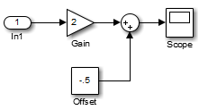
The following model, sink_examp, contains an atomic subsystem,theSink.
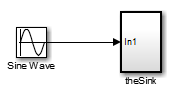
The subsystem theSink applies a gain and an offset to its input signal and displays it on a Scope block.
If theSink is declared as a Signal Viewing Subsystem, the generated target application includes only the code for the Sine Wave block. IftheSink is selected and armed in the External Signal & Triggering dialog box, the target application uploads the sine wave signal totheSink during simulation. You can then modify the parameters of the blocks within theSink and observe the uploaded signal.
If theSink were not declared as a Signal Viewing Subsystem, its Gain, Constant, and Sum blocks would run as subsystem code on the target system. The Sine Wave signal would be uploaded to the Simulink engine after being processed by these blocks, and viewed onsink_examp/theSink/Scope2. Processing demands on the target system would be increased by the additional signal processing, and by the downloading of changes in block parameters from the host.
Supported Blocks for Data Archiving
In external mode, you can use the following types of blocks to archive data to disk:
- Scope blocks
- To Workspace blocks
You configure data archiving by using the Enable Data Archiving dialog box, as described in Configure Host Archiving of Target Application Signal Data.
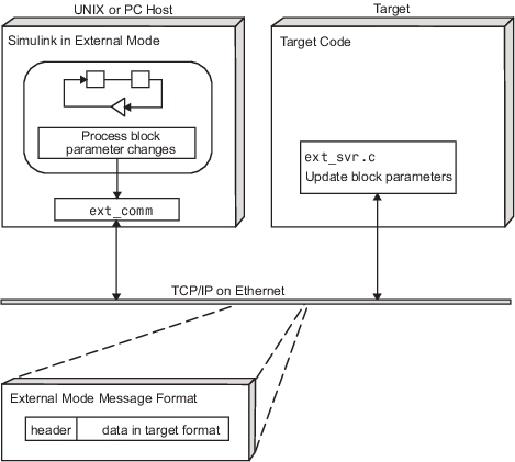
External Mode Mechanism for Downloading Tunable Parameters
Depending on the setting of the Default parameter behavior option when the target application is generated, there are differences in the way parameter updates are handled. Download Mechanism describes the operation of external mode communication with Default parameter behavior set toTunable. Inlined and Tunable Parameters describes the operation of external mode with Default parameter behavior set toInlined.
Download Mechanism
In external mode, the Simulink engine does not simulate the system represented by the block diagram. By default, when external mode is enabled, the Simulink engine downloads parameters to the target system. After the initial download, the engine remains in a waiting mode until you change parameters in the block diagram or until the engine receives data from the target.
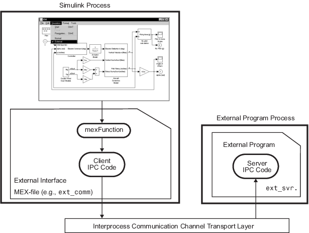
When you change a parameter in the block diagram, the Simulink engine calls the external interface MEX-file, passing new parameter values (along with other information) as arguments. The external interface MEX-file contains code that implements one side of the interprocess communication (IPC) channel. This channel connects the Simulink process (where the MEX-file executes) to the process that is executing the external program. The MEX-file transfers the new parameter values by using this channel to the external program.
The other side of the communication channel is implemented within the external program. This side writes the new parameter values into the target's parameter structure (_`model`__P).
The Simulink side initiates the parameter download operation by sending a message containing parameter information to the external program. In the terminology of client/server computing, the Simulink side is the client and the external program is the server. The two processes can be remote, or they can be local. Where the client and server are remote, a protocol such as TCP/IP is used to transfer data. Where the client and server are local, a serial connection or shared memory can be used to transfer data.
The next figure shows this relationship. The Simulink engine calls the external interface MEX-file whenever you change parameters in the block diagram. The MEX-file then downloads the parameters to the external program by using the communication channel.
External Mode Architecture
Inlined and Tunable Parameters
By default, parameters (except those listed in TCP/IP and Serial External Mode Limitations) in an external mode program are tunable; that is, you can change them by using the download mechanism described in this section.
If you set Default parameter behavior toInlined (on the pane of the Configuration Parameters dialog box), the Simulink Coder code generator embeds the numerical values of model parameters (constants), instead of symbolic parameter names, in the generated code. Inlining parameters generates smaller and more efficient code. However, inlined parameters, because they effectively become constants, are not tunable.
The Simulink Coder software lets you improve overall efficiency by inlining most parameters, while at the same time retaining the flexibility of run-time tuning for selected parameters that are important to your application. When you inline parameters, you can useSimulink.Parameter objects to remove individual parameters from inlining and declare them to be tunable. In addition, you can use these objects to control how parameters are represented in the generated code.
For more information on tunable parameters, see Create Tunable Calibration Parameter in the Generated Code.
Automatic Parameter Uploading on Host/Target Connection. Each time the Simulink engine connects to a target application that was generated withDefault parameter behavior set toInlined, the target application uploads the current value of its tunable parameters to the host. These values are assigned to the corresponding MATLAB workspace variables. This procedure synchronizes the host and target with respect to parameter values. If the tunable parameters are stored in the model workspace or a data dictionary, the values are not uploaded and Simulink produces a warning.
Workspace variables required by the model must be initialized at the time of host/target connection. Otherwise the uploading cannot proceed and an error results. Once the connection is made, these variables are updated to reflect the current parameter values on the target system.
Automatic parameter uploading takes place only if the target application was generated with Default parameter behavior set toInlined. Download Mechanism describes the operation of external mode communication with Default parameter behavior set toTunable.
Choose Communication Protocol for Client and Server
- Introduction
- Using the TCP/IP Implementation
- Using the Serial Implementation
- Run the External Program
- Implement an External Mode Protocol Layer
Introduction
The Simulink Coder product provides code to implement both the client and server side of external mode communication using either TCP/IP or serial protocols. You can use the socket-based external mode implementation provided by the Simulink Coder product with the generated code, provided that your target system supports TCP/IP. If not, use or customize the serial transport layer option provided.
A low-level transport layer handles physical transmission of messages. Both the Simulink engine and the model code are independent of this layer. Both the transport layer and code directly interfacing to the transport layer are isolated in separate modules that format, transmit, and receive messages and data packets.
Using the TCP/IP Implementation
You can use TCP/IP-based client/server implementation of external mode with real-time programs on The Open Group UNIX® or PC systems. For help in customizing external mode transport layers, seeCreate a Transport Layer for TCP/IP or Serial External Mode Communication.
To use Simulink external mode over TCP/IP:
- Make sure that the external interface MEX-file for your target's TCP/IP transport is specified.
Targets provided by MathWorks® specify the name of the external interface MEX-file in_`matlabroot`_/toolbox/simulink/simulink/extmode_transports.m. The name of the interface appears as uneditable text in the External mode configuration section of the Interface pane of the Configuration Parameters dialog box. The TCP/IP default isext_comm.
To specify a TCP/IP transport for a custom target, you must add an entry of the following form to ansl_customization.mfile on the MATLAB path:
function sl_customization(cm)
cm.ExtModeTransports.add('stf.tlc', 'transport', 'mexfile', 'Level1');
%end function_`stf`_.tlcis the name of the system target file for which you are registering the transport (for example,'mytarget.tlc')_`transport`_is the transport name to display in the Transport layer menu on theInterface pane of the Configuration Parameters dialog box (for example,'tcpip')_`mexfile`_is the name of the transport's associated external interface MEX-file (for example,'ext_comm')
You can specify multiple targets and/or transports with additionalcm.ExtModeTransports.addlines, for example:
function sl_customization(cm)
cm.ExtModeTransports.add('mytarget.tlc', 'tcpip', 'ext_comm', 'Level1');
cm.ExtModeTransports.add('mytarget.tlc', 'serial', ...
'ext_serial_win32_comm', 'Level1');
%end function
- Be sure that the template makefile is configured to link the source files for the TCP/IP server code and that it defines the compiler flags when building the generated code.
- Build the external program.
- Run the external program.
- Set the Simulink model to external mode and connect to the target.
The next figure shows the structure of the TCP/IP-based implementation.
TCP/IP-Based Client/Server Implementation for External Mode
MEX-File Optional Arguments for TCP/IP Transport. In the External Target Interface dialog box, you can specify optional arguments that are passed to the external mode interface MEX-file for communicating with executing targets.
- Target network name: the network name of the computer running the external program. By default, this is the computer on which the Simulink product is running, for example,
'myComputer'. You can also use the IP address, for example,'148.27.151.12'. - Verbosity level: controls the level of detail of the information displayed during the data transfer. The value is either
0or1and has the following meaning:0— No information1— Detailed information - TCP/IP server port number: The default value is
17725. You can change the port number to a value between256and65535to avoid a port conflict.
The arguments are positional and must be specified in the following order:
For example, if you want to specify the verbosity level (the second argument), then you must also specify the target network name (the first argument). Arguments can be delimited by white space or commas. For example:
You can specify command-line options to the external program when you launch it. SeeRun the External Program.
Using the Serial Implementation
Controlling host/target communication on a serial channel is similar to controlling host/target communication on a TCP/IP channel.
To use Simulink external mode over a serial channel, you must:
- Make sure that the external interface MEX-file for your target's serial transport is specified.
Targets provided by MathWorks specify the name of the external interface MEX-file in_`matlabroot`_/toolbox/simulink/simulink/extmode_transports.m. The name of the interface appears as uneditable text in the External mode configuration section of the Interface pane of the Configuration Parameters dialog box. The serial default isserial.
To specify a serial transport for a custom target, you must add an entry of the following form to ansl_customization.mfile on the MATLAB path:
function sl_customization(cm)
cm.ExtModeTransports.add('stf.tlc', 'transport', 'mexfile', 'Level1');
%end function_`stf`_.tlcis the name of the system target file for which you are registering the transport (for example,'mytarget.tlc')_`transport`_is the transport name to display in the Transport layer menu on theInterface pane of the Configuration Parameters dialog box (for example,'serial')_`mexfile`_is the name of the transport's associated external interface MEX-file (for example,'ext_serial_win32_comm')
You can specify multiple targets and/or transports with additionalcm.ExtModeTransports.addlines, for example:
function sl_customization(cm)
cm.ExtModeTransports.add('mytarget.tlc', 'tcpip', 'ext_comm', 'Level1');
cm.ExtModeTransports.add('mytarget.tlc', 'serial', ...
'ext_serial_win32_comm', 'Level1');
%end function
- Be sure that the template makefile is configured to link the source files for the serial server code and that it defines the compiler flags when building the generated code.
- Build the external program.
- Run the external program.
- Set the Simulink model to external mode and connect to the target.
MEX-File Optional Arguments for Serial Transport. In the MEX-file arguments field of theInterface pane of the Configuration Parameters dialog box, you can specify arguments that are passed to the external mode interface MEX-file for communicating with the executing targets. For serial transport, the optional arguments to ext_serial_win32_comm are as follows:
- Verbosity level: This argument controls the level of detail of the information displayed during data transfer. The value of this argument is:
0(no information), or1(detailed information)
- Serial port ID: The port ID of the host, specified as an integer or character vector. For example, specify the port ID of a USB to serial converter as
'/dev/ttyusb0'. Simulink Coder prefixes integer port IDs with\\.\COMon Windows® and by/dev/ttySon Unix.
When you start the target application using a serial connection, you must specify the port ID to use to connect it to the host. Do this by including the-portcommand-line option. For example: - Baud rate: Specify an integer value. The default value is
57600.
The MEX-file options arguments are positional and must be specified in the following order:
For example, if you want to specify the serial port ID (the second argument), then you must also specify the verbosity level (the first argument). Arguments can be delimited by white space or commas. For example:
When you launch the external program, you can specify command-line options.
Run the External Program
Before you can use the Simulink product in external mode, the external program must be running.
If the target application is executing on the same machine as the host and communication is through a loopback serial cable, the target's port ID must differ from that of the host (as specified in the MEX-file arguments edit field).
To run the external program, you type a command of the form:
_`model`_ is the name of the external program and _`-opt1`_ ... -_`optN`_ are options. (See Command-Line Options for the External Program.) In the examples in this section, the name of the external program is ext_example.
Running the External Program in the Windows Environment. In the Windows environment, you can run the external programs in either of the following ways:
- Open a Command Prompt window. At the command prompt, type the name of the target executable, followed by possible options, such as:
- Alternatively, you can launch the target executable from the MATLAB Command Window. The command must be preceded by an exclamation point (
!) and followed by an ampersand (&), as in the following example:
!ext_example -tf inf -w &
The ampersand (&) causes the operating system to spawn another process to run the target executable. If you do not include the ampersand, the program still runs, but you cannot enter commands at the MATLAB command prompt or manually terminate the executable.
Running the External Program in the UNIX Environment. In the UNIX environment, you can run the external programs in either of the following ways:
- Open an
Xtermwindow. At the command prompt, type the name of the target executable, followed by possible options, such as: - Alternatively, you can launch the target executable from the MATLAB Command Window. You must run it in the background so that you can still access the Simulink environment. The command must be preceded by an exclamation point (
!), dot slash (./ indicating the current directory), and followed by an ampersand (&), as in the following example:
!./ext_example -tf inf -w &
The ampersand (&) causes the operating system to spawn another process to run the target executable.
Command-Line Options for the External Program. External mode target executables generated by the Simulink Coder code generator support the following command-line options:
-tf n
The-tfoption overrides the stop time set in the Simulink model. The argumentnspecifies the number of seconds the program will run. The valueinfdirects the model to run indefinitely. In this case, the model code runs until the target application receives a stop message from the Simulink engine.
The following example sets the stop time to 10 seconds.
When integer-only ERT targets are built and executed in external mode, the stop time parameter (-tf) is interpreted by the target as the number of base rate steps rather than the number of seconds to execute.
-w
Instructs the target application to enter a wait state until it receives a message from the host. At this point, the target is running, but not executing the model code. The start message is sent when you select Start Real-Time Code from the Simulation menu or click theStart Real-Time Code button in the External Mode Control Panel.
Use the-woption if you want to view target application execution data from time step 0, or if you want to modify parameters before the target application begins execution of model code.-port n
Specifies the TCP/IP port number or the serial port ID,n, for the target application. The port number of the target application must match that of the host for TCP/IP transport. The port number depends on the type of transport.- For TCP/IP transport: Port number is an integer between
256and65535, with the default value being17725. The selected port must not be used by another TCP/IP service that runs on the target hardware. - For serial transport: Port ID is an integer or a character vector. For example, specify the port ID of a USB to serial converter as
'/dev/ttyusb0'
- For TCP/IP transport: Port number is an integer between
-baud r
Specified as an integer, this option is only available for serial transport.
Implement an External Mode Protocol Layer
If you want to implement your own transport layer for external mode communication, you must modify certain code modules provided by the Simulink Coder product and create a new external interface MEX-file. See Create a Transport Layer for TCP/IP or Serial External Mode Communication.
Use External Mode Programmatically
You can run external mode simulations from the MATLAB command line or programmatically in scripts. Use theget_param and set_param commands to retrieve and set the values of model simulation command-line parameters, such asSimulationMode and SimulationCommand, and external mode command-line parameters, such as ExtModeCommand andExtModeTrigType.
The following model simulation commands assume that a Simulink model is open and that you have loaded a target application to which the model will connect using external mode.
- Change the Simulink model to external mode:
set_param(gcs,'SimulationMode','external') - Connect the open model to the loaded target application:
set_param(gcs,'SimulationCommand','connect') - Start running the target application:
set_param(gcs,'SimulationCommand','start') - Stop running the target application:
set_param(gcs,'SimulationCommand','stop') - Disconnect the target application from the model:
set_param(gcs,'SimulationCommand','disconnect')
The set_param commands that use the 'SimulationCommand' argument are asynchronous. If you run the commands successively from a script, each command starts without waiting for the previous command to complete. To check that each command is complete, in the script, use the get_param command with the'SimulationStatus' argument. For example, for steps 1 to 3, specify these commands in the script:
set_param(gcs,'SimulationMode','external'); set_param(gcs,'SimulationCommand','connect');
isExternalSimulationActive = false; while ~isExternalSimulationActive simStatus = get_param(gcs, 'SimulationStatus'); isExternalSimulationActive = strcmp(simStatus, 'external'); end set_param(gcs,'SimulationCommand','start');
For more information, see Run Simulations Programmatically.
The Diagnostic Viewer displays error messages produced by the get_param and set_param commands.
To tune a workspace parameter, change its value at the command prompt. If the workspace parameter is a Simulink.Parameter object, assign the new value to the Value property.
myVariable = 5.23; myParamObj.Value = 5.23;
To download the workspace parameter in external mode, you update the model diagram. The following model simulation command initiates a model update:
set_param(gcs,'SimulationCommand','update')
To trigger or cancel data uploading to scopes, use the ExtModeCommand values armFloating and cancelFloating, orarmWired and cancelWired. For example, to trigger and then cancel data uploading to wired (nonfloating) scopes:
set_param(gcs,'ExtModeCommand','armWired') set_param(gcs,'ExtModeCommand','cancelWired')
The next table lists external mode command-line parameters that you can use inget_param and set_param commands. The table provides brief descriptions, valid values (bold type highlights defaults), and a mapping to External Mode dialog box equivalents. For external mode parameters that are equivalent toInterface pane options in the Configuration Parameters dialog box, see Model Configuration Parameters: Code Generation Interface.
External Mode Command-Line Parameters
| Parameter and Values | Dialog Box Equivalent | Description |
|---|---|---|
| ExtModeAddSuffixToVar off, on | Enable Data Archiving: Append file suffix to variable names check box | Increment variable names for each incremented filename. |
| ExtModeArchiveDirName character vector | Enable Data Archiving: Directory text field | Save data in specified folder. |
| ExtModeArchiveFileName character vector | Enable Data Archiving: File text field | Save data in specified file. |
| ExtModeArchiveMode character vector - off,auto, manual | Enable Data Archiving: Enable archiving check box | Activate automated data archiving features.To specifymanual, run set_param(gcs, 'ExtModeArchiveMode', 'manual').Note that if you specifyauto, ExtModeAutoIncOneShot is set toon. |
| ExtModeArmWhenConnect off, on | External Signal & Triggering: Arm when connecting to target check box | Arm the trigger as soon as the Simulink Coder software connects to the target. |
| ExtModeAutoIncOneShot off, on | Enable Data Archiving: Increment file after one-shot check box | Save new data buffers in incremental files. |
| ExtModeAutoUpdateStatusClock (Windows platforms only) off,on | Not available | Continuously upload and display target time on the model window status bar. |
| ExtModeBatchMode off, on | External Mode Control Panel: Batch download check box | Enable or disable downloading of parameters in batch mode. |
| ExtModeChangesPending off, on | Not available | When ExtModeBatchMode is enabled, indicates whether parameters remain in the queue of parameters to be downloaded to the target. |
| ExtModeCommand character vector - armFloating,armWired, cancelFloating,cancelWired | armFloating and cancelFloating are equivalent to selecting and clearing External Mode Control Panel check box > armWired and cancelWired are equivalent to External Mode Control Panel buttons Arm Trigger and Cancel Trigger | Issue an external mode command to the target application. |
| ExtModeConnected off, on | External Mode Control Panel: Connect/Disconnect button | Indicate the state of the connection with the target application. |
| ExtModeEnableFloating off,on | External Mode Control Panel: Enable data uploading check box | Enable or disable the arming and canceling of triggers when a connection is established with floating scopes. |
| ExtModeIncDirWhenArm off, on | Enable Data Archiving: Increment directory when trigger armed check box | Write log files to incremental folders each time the trigger is armed. |
| ExtModeLogAll off, on | External Signal & Triggering: Select all check box | Upload available signals from the target to the host. |
| ExtModeParamChangesPending off, on | Not available | When the Simulink Coder software is connected to the target andExtModeBatchMode is enabled, indicates whether parameters remain in the queue of parameters to be downloaded to the target. More efficient than ExtModeChangesPending, because it checks for a connection to the target. |
| ExtModeSkipDownloadWhenConnect off, on | Not available | Connect to the target application without downloading parameters. |
| ExtModeTrigDelay integer (0) | External Signal & Triggering: Delay text field | Specify the amount of time (expressed in base rate steps) that elapses between a trigger occurrence and the start of data collection. |
| ExtModeTrigDirection character vector - rising,falling, either | External Signal & Triggering: Direction menu | Specify the direction in which the signal must be traveling when it crosses the threshold value. |
| ExtModeTrigDuration integer (1000) | External Signal & Triggering: Duration text field | Specify the number of base rate steps for which external mode is to log data after a trigger event. |
| ExtModeTrigDurationFloating character vector - integer (auto) | External Mode Control Panel: Duration text field | Specify the duration for floating scopes. If auto is specified, the value of ExtModeTrigDuration is used. |
| ExtModeTrigElement character vector - integer,any,last | External Signal & Triggering: Element text field | Specify the elements of the input port of the specified trigger block that can cause the trigger to fire. |
| ExtModeTrigHoldOff integer (0) | External Signal & Triggering: Hold-off text field | Specify the base rate steps between when a trigger event terminates and the trigger is rearmed. |
| ExtModeTrigLevel integer (0) | External Signal & Triggering: Level text field | Specify the threshold value the trigger signal must cross to fire the trigger. |
| ExtModeTrigMode character vector - normal,oneshot | External Signal & Triggering: Mode menu | Specify whether the trigger is to rearm automatically after each trigger event or whether only one buffer of data is to be collected each time the trigger is armed. |
| ExtModeTrigPort character vector - integer (1), last | External Signal & Triggering: Port text field | Specify the input port of the specified trigger block for which elements can cause the trigger to fire. |
| ExtModeTrigType character vector - manual,signal | External Signal & Triggering: Source menu | Specify whether to start logging data when the trigger is armed or when a specified trigger signal satisfies trigger conditions. |
| ExtModeUploadStatus character vector - inactive,armed, uploading | Not available | Return the status of the external mode upload mechanism — inactive, armed, or uploading. |
| ExtModeWriteAllDataToWs off, on | Enable Data Archiving: Write intermediate results to workspace check box | Write intermediate results to the workspace. |
Animate Stateflow Charts in External Mode
If you have Stateflow®, you can animate a chart in external mode. In external mode, you can animate states in a chart, and view test point signals in a floating scope or signal viewer.
- Animate States During Simulation in External Mode
- View Test Point Data in Floating Scopes and Signal Viewers
Animate States During Simulation in External Mode
To animate states in a chart in external mode:
- Load the chart you want to animate to the target machine.
- In the Configuration Parameters dialog box, select the External mode check box.
- Open the External Mode Control Panel dialog box.
- Click Signal & Triggering.
- In the External Signal & Triggering dialog box, set these parameters.
In: Select: Signal selection pane Chart you want to animate Trigger options pane Arm when connecting to target check box Trigger options pane normal from drop-down menu inMode field - Build the model to generate an executable file.
- Deploy the target application.
- Connect Simulink to the target application.
- Start execution of the generated model code. The chart highlights states as they execute.
View Test Point Data in Floating Scopes and Signal Viewers
When you simulate a chart in external mode, you can designate chart data of local scope to be test points and view the test point data in floating scopes and signal viewers.
To view test point data during simulation in external mode:
- Open the Model Explorer and for each data you want to view, follow these steps:
- In the middle Contents pane, select the state or local data of interest.
- In the right Dialog pane, select theLogging tab and select Test point check box.
- From a floating scope or signal viewer, click the signal selection button:

The Signal Selector dialog box opens. - In the Signal Selector Model hierarchy pane, select the chart.
- In the Signal Selector List contents menu, selectTestpointed/Logged signals only and then select the signals you want to view.
- Simulate the model in external mode as described in Animate States During Simulation in External Mode.
The scope or viewer displays the values of the test point signals as the simulation runs.
For more information, see Behavior of Scopes and Viewers with Rapid Accelerator Mode.
TCP/IP and Serial External Mode Limitations
| Feature | Details |
|---|---|
| Service code interface | Using external mode for tuning parameters and monitoring signals as generated code executes in a target environment is not supported for code generated from component models configured with an ERT-based system target file and service code interface. |
| Changing parameters | In general, you cannot change a parameter if doing so results in a change in the structure of the model. For example, you cannot changeThe number of states, inputs, or outputs of a blockThe sample time or the number of sample timesThe integration algorithm for continuous systemsThe name of the model or of a blockIf you make these changes to the block diagram, then you must rebuild the program with newly generated code.You can change parameters in transfer function and state space representation blocks in specific ways:The parameters (numerator and denominator polynomials) for theTransfer Fcn (continuous and discrete) and Discrete Filter blocks can be changed (as long as the number of states does not change).Zero entries in the State-Space and Zero Pole (both continuous and discrete) blocks in the user-specified or computed parameters (that is, the A, B, C, and D matrices obtained by a zero-pole to state-space transformation) cannot be changed once external simulation is started.In the State-Space block, if you specify the matrices in the controllable canonical realization, then all changes to the A, B, C, D matrices that preserve this realization and the dimensions of the matrices are allowed.If the Simulink block diagram does not match the external program, Simulink produces an error stating that the checksums do not match. The checksums take into account the top models, but not referenced models. Use the updated block diagram to rebuild the target application. |
| Uploading data | For parameters with fixed-point values, uploading of parameter values from the target application is not supported. |
| Uploading variable-size signals | Uploading of variable-size signals is not supported for these targets: Simulink Real-Time™ Texas Instruments® C2000™ |
| Signal value display in simulation | Graphical display of signal values in models (described in Display Signal Values in Model Diagrams) is not supported. For example, you cannot use the menu selections , , and . |
| Tunable structure parameters | Uploading or downloading of tunable structure parameters is not supported. |
| C++ code | Generated C++ code is not supported. The simulation produces an error if you specify these configuration parameter settings: Language — C++Code interface packaging — C++ class |
| Pure integer code | Pure integer code is supported.If you do not specify-tf finalTime in the execution command, the target application runs the generated model code indefinitely, ignoring StopTime.If you specify -tf_finalTime_ in the execution command: The finalTime value represents base rate steps, not seconds.The maximum value for finalTime, in ticks, isMAX_int32_T.When the 16-bit or 32-bit tick counter overflows, the simulation time inScope blocks returns to zero. |
| Half precision | Half-precision data types are not supported. |
| Simulink.ImageType | Simulink.ImageType data type is not supported. |
| Archiving data | For archiving data to disk, Scope and To Workspace blocks are supported. However, other scopes are not supported for data archiving. For example, you cannot use Floating Scope blocks or Viewers and Generators Manager viewer objects to archive data. |
| Scopes in referenced models | In a model hierarchy, if the top model simulates in external mode and a referenced model simulates in normal or accelerator mode, scopes in the referenced model are not displayed.However, if the top model is changed to simulate in normal mode, the behavior of scopes in the referenced models differs between normal and accelerator mode. Scopes in a referenced model simulating in normal mode are displayed, while scopes in a referenced model simulating in accelerator mode are not displayed. |
| Scope and Display blocks connected to Simulink message blocks | During external mode simulations, Scope andDisplay blocks connected to Simulink message blocks do not provide displays. |
| Simulation start time | Nonzero simulation start times are not supported. In the Configuration Parameters dialog box, pane, leaveStart time set to the default value of0.0. |
| Intermediate step values | Some Simulink blocks can generate multiple values in a simulation time step. For example: A Simulink Function or Function-Call Subsystem block that is invoked multiple times in a time step.Iterator subsystem blocks that execute multiple times in a time step.For each time step in an external mode simulation, Simulink uploads from the target application only the final values of such blocks. Simulink does not upload the intermediate values generated during the step. |
| File-scoped data | File-scoped data are not supported, for example, data items to which you apply the built-in custom storage class, FileScope. File-scoped data are not externally accessible. |
| Signals with custom storage classes | Uploading of signals with custom storage classes (CSC) is not supported. |
| Use of printf Statements | To show target application error and information messages on the target hardware display, you can use printf calls. For some target hardware, the use of printf statements can increase the external mode binary file size. To disable printf calls, specify the preprocessor macro definition EXTMODE_DISABLEPRINTF for your target application compiler. |
| Command-line arguments | You can use command-line arguments for running target applications. These limitations apply: Parsing of the command-line arguments requires thesscanf function, which increases the program size for some target hardware.Some target applications do not accept command-line arguments.If your target hardware does not support the parsing of command-line arguments, specify the preprocessor macro definitionEXTMODE_DISABLE_ARGS_PROCESSING=1 for your target application compiler.To replace the -w option, you can use this command to specify that the target application enters and stays in a wait state until it receives a Connect message from Simulink:set_param(modelName, 'OnTargetWaitForStart', 'on');The build process provides the required option (-DON_TARGET_WAIT_FOR_START=1) to the compiler. |
| Row-major code generation | Code generated with the row-major format is not supported. |
| Simulation data export | The export of simulation output, signal, and state data is not supported. |