Simulink.sdi.setSignalInputProcessingMode - Specify value for Input Processing signal property - MATLAB (original) (raw)
Main Content
Specify value for Input Processing signal property
Syntax
Description
Simulink.sdi.setSignalInputProcessingMode([blkPath](#mw%5F489061c5-2771-495e-8891-fa1fc9073d4b),[port](#mw%5F44a61ed5-066b-414c-8e53-a0379879758c),[mode](#mw%5F550a2761-e645-4dbe-9c7d-b444a01834dc)) specifies mode as the value of the Input Processing property for the signal at the specified block path and port. You can only specify theInput Processing property for logged signals.
The Input Processing setting affects the format of the logged data and how the Simulation Data Inspector and dashboard blocks display the signal. You can configure a signal for frame-based or sample-based input processing.
Simulink.sdi.setSignalInputProcessingMode([h](#mw%5F8f8eba09-cdc6-4ec2-829f-b5af2aed8476),[mode](#mw%5F550a2761-e645-4dbe-9c7d-b444a01834dc)) specifies mode as the value of the Input Processing property for the signal that corresponds to the line handle, h.
Examples
Many signal processing applications process data using frames, rather than individual signal values. A frame consists of signal values for several sample times. To process signals as frame-based in your model, specify frame-based processing in the blocks. To log and visualize frame-based signals, set the Input Processing setting to Columns as channels (frame based) in the Instrumentation Properties for the signal.
This example uses a model from the DSP System Toolbox™ to show how to programmatically specify the Input Processing setting for signals in a model using the Simulink.sdi.setSignalInputProcessingMode function. The model uses frame-based signals and demonstrates single sideband (SSB) modulation.
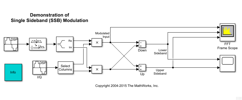
Configure Signal Logging
Open or load the model ssbdemo_frame. This example illustrates a scripting workflow and only loads the model.
load_system('ssbdemo_frame');
The model includes visualization blocks and does not use signal logging. Mark the signals that represent the upper sideband and lower sideband for logging.
upperSB_block = 'ssbdemo_frame/Up'; lowerSB_block = 'ssbdemo_frame/Down';
Simulink.sdi.markSignalForStreaming(upperSB_block,1,'on') Simulink.sdi.markSignalForStreaming(lowerSB_block,1,'on')
If you simulate the model as-is, the signals would be logged as though they were sample-based, so each element in a sample would be treated as a separate channel. To log the signals as frame-based, specify the Input Processing setting for the signal as frame using the Simulink.sdi.setSignalInputProcessingMode function.
Simulink.sdi.setSignalInputProcessingMode(upperSB_block,1,'frame'); Simulink.sdi.setSignalInputProcessingMode(lowerSB_block,1,'frame');
After configuring the upper and lower sideband signals for logging and as frame-based, the data logs to the workspace and the Simulation Data Inspector in a frame-based format, so each column in a sample is treated as a channel in the signal. You can view and analyze the data in the Simulation Data Inspector or using its programmatic interface.
Input Arguments
Block path for the block that produces the signal, specified as a string or character array.
Example: "vdp/Mu"
Block output port number for the port that produces the signal, specified as a scalar.
Example: 1
Input Processing property value for the signal, returned as"signal" or "frame".
sample— Sample-based input processing, where each element in a sample is treated as a channel.frame— Frame-based input processing, where each column in a sample is treated as a channel.
Line handle for the signal. You can get the line handle for a signal using theget_param function with the'LineHandles' option. For example, to access the line handle for the output of the Mu block in the modelvdp:
MuLineHandles = get_param('vdp/Mu','LineHandles'); MuOutputLineHandle = MuLineHandles.Outport;
Example: MuOutputLineHandle
Version History
Introduced in R2020a