Simulink.SubSystem.convertToModelReference - Convert subsystems to models - MATLAB (original) (raw)
Convert subsystems to models
Syntax
Description
Simulink.SubSystem.convertToModelReference([blk](#mw%5F8e9f6ba7-432e-48ec-92a2-4c231bab718d),UseConversionAdvisor=true) opens the Model Reference Conversion Advisor for the subsystem specified by blk.
Before you use this function, load the model that contains the subsystem.
[[t](#buo1swk-1-success),[h](#buo1swk-1-mdlRefBlkHs)] = Simulink.SubSystem.convertToModelReference([blks](#buo1swk-1-subsys),[mdls](#buo1swk-1-mdlRefs)) converts one or more subsystems specified by blks to models with names specified by mdls.
For each subsystem that the function converts, the function:
- Creates a model.
- Copies the contents of the subsystem into the new model.
- Updates the root-level input and output blocks of the new model to use the compiled attributes from the original subsystem.
- Copies the configuration set of the parent model to the new model or references the same configuration set as the parent model. The conversion can change some configuration settings for the new model to support using the new model as a referenced model.
When applicable, the function also:
- Copies the model workspace contents used by the subsystem from the parent model to the new model.
- Applies the data dictionary used by the parent model to the new model.
- Creates the
Simulink.Busobjects,Simulink.Signalobjects, and tunable parameters that the new model requires. - Creates a system mask for the new model based on the block mask of the originalSubsystem block. System masks do not support some of the functionalities of block masks, such as mask initialization code. For more information, see Introduction to System Mask.
- Copies the requirements links created with Requirements Toolbox™ software from the original Subsystem block to the newModel block.
[[t](#buo1swk-1-success),[h](#buo1swk-1-mdlRefBlkHs)] = Simulink.SubSystem.convertToModelReference([blks](#buo1swk-1-subsys),[mdls](#buo1swk-1-mdlRefs),[Name=Value](#namevaluepairarguments)) specifies options using one or more name-value arguments in addition to the input arguments in previous syntaxes. For example, to apply automatic fixes, setAutoFix to true.
Examples
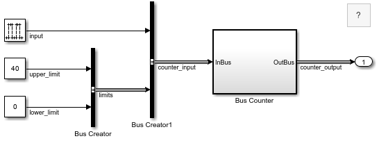
Open and compile the model named sldemo_mdlref_conversion. For the conversion to succeed, the model that contains the subsystem must compile successfully.
mdl = "sldemo_mdlref_conversion"; open_system(mdl); set_param(mdl,SimulationCommand="Update")

The model compiles without warnings or errors.
Open the Model Reference Conversion Advisor for the Subsystem block named Bus Counter.
blk = "sldemo_mdlref_conversion/Bus Counter"; Simulink.SubSystem.convertToModelReference(blk,... UseConversionAdvisor=true);
Updating Model Advisor cache... Model Advisor cache updated. For new customizations, to update the cache, use the Advisor.Manager.refresh_customizations method.
The Model Reference Conversion Advisor opens.
Open and compile the model named sldemo_mdlref_conversion. For the conversion to succeed, the model that contains the subsystem must compile successfully.
mdl = "sldemo_mdlref_conversion"; open_system(mdl); set_param(mdl,SimulationCommand="Update")
The model compiles without warnings or errors.
Open the Model Reference Conversion Advisor for the Subsystem block named Bus Counter.
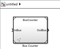
blk = "sldemo_mdlref_conversion/Bus Counter"; newmdl = "BusCounter"; Simulink.SubSystem.convertToModelReference(blk,newmdl);
Successfully converted Subsystem block to Model block.
By default, the function does not replace the Subsystem block with a Model block. Instead, the function opens a new window that contains a Model block that references the new model.
Open and compile the example model named sldemo_mdlref_conversion. For the conversion to succeed, the model that contains the subsystem must compile successfully.
mdl = "sldemo_mdlref_conversion"; open_system(mdl) set_param(mdl,SimulationCommand="Update")

The model compiles without warnings or errors.
Convert the contents of the Subsystem block named Bus Counter to a referenced model named BusCounter, specifying these options:
- Automatically fix problems when possible.
- Replace the Subsystem block with a Model block that references the new model.
- Check the simulation results before and after conversion.
subsys = "sldemo_mdlref_conversion/Bus Counter"; newmdl = "BusCounter"; Simulink.SubSystem.convertToModelReference(subsys,newmdl,... AutoFix=true,ReplaceSubsystem=true,CheckSimulationResults=true);
Successfully converted Subsystem block to Model block.

The Subsystem block is replaced by a Model block that references the model named BusCounter.
One call to the Simulink.SubSystem.convertToModelReference function can convert multiple subsystems to referenced models.
Open and compile the model named f14. For the conversion to succeed, the model that contains the subsystem must compile successfully.
mdl = "f14"; open_system(mdl) set_param(mdl,SimulationCommand="Update")

The model compiles without warnings or errors.
Prepare the model for conversion to eliminate or reduce the number of issues identified during conversion.
To be able to check that the simulation results are equivalent before and after conversion, log the output of the model using Dataset format.
set_param(mdl,SaveOutput="on",SaveFormat="Dataset")
The new referenced model will inherit its configuration parameter settings from the parent model. Update the f14 model to use the recommended setting for signal resolution. This setting supports only explicitly specified signal resolution for Simulink.Signal objects.
set_param(mdl,SignalResolutionControl="UseLocalSettings")
Convert the contents of the Subsystem blocks named Controller and Aircraft Dynamics Model to referenced models, specifying these options:
- Automatically fix problems.
- Replace the Subsystem blocks with Model blocks that reference the new models.
- Check simulation results before and after conversion.
ss1 = "f14/Controller"; ss2 = "f14/Aircraft Dynamics Model"; mdl1 = "Controller"; mdl2 = "AircraftDynamics"; Simulink.SubSystem.convertToModelReference([ss1 ss2],[mdl1 mdl2],... AutoFix=true,ReplaceSubsystem=true,CheckSimulationResults=true)
Successfully converted Subsystem block to Model block.

The Subsystem blocks named Controller and Aircraft Dynamics Model are replaced by Model blocks that reference the models named Controller and AircraftDynamics, respectively.
Input Arguments
Subsystem block path or handle, specified as a numeric scalar, character vector, or string scalar.
For information on which subsystems you can convert, see Conditionally Execute Referenced Models.
Data Types: double | char | string
Subsystem block paths or handles, specified as a numeric array, character vector, cell array of character vectors, or string array.
For information on which subsystems you can convert, see Conditionally Execute Referenced Models.
When you specify multiple subsystems to convert, the conversion process attempts to convert each subsystem. Successfully converted subsystems produce referenced models, even if the conversions of other subsystems fail.
You cannot convert a parent subsystem and a child of that subsystem at the same time.
Tips
Specifying multiple subsystems to convert with one command can save time compared to converting each subsystem separately. The conversion process for multiple subsystems compiles the model only once.
When you specify multiple subsystems:
- In the model, consider setting a short simulation time.
- In the function, consider setting AutoFix,ReplaceSubsystem, andCheckSimulationResults to
true.
Data Types: double | char | string | cell
Unique names for new models, specified as a character vector, cell array of character vectors, or string array.
For information about valid model file names, see Choose Valid Model File Names.
When you specify multiple subsystems to convert, specify the same number of model names. Each model name corresponds to a specified subsystem, in the same order.
Data Types: char | string | cell
Name-Value Arguments
Specify optional pairs of arguments asName1=Value1,...,NameN=ValueN, where Name is the argument name and Value is the corresponding value. Name-value arguments must appear after other arguments, but the order of the pairs does not matter.
Before R2021a, use commas to separate each name and value, and enclose Name in quotes.
Example: Simulink.SubSystem.convertToModelReference(blk,mdl,AutoFix=true,ReplaceSubsystem=true)
Conversion
Automatic fixes for conversion issues, specified as false ortrue.
When you set AutoFix to true, the advisor fixes some conversion issues automatically. For issues that the advisor cannot fix, you must address the issues manually.
The advisor can fix conversion issues such as Goto andFrom blocks that cross the subsystem boundary. Based on the automatic fixes, the new model can have more ports than the original subsystem.
To reduce the number of fixes required during the conversion, see Prepare Subsystem for Conversion.
Dependencies
The software ignores this option when you set Force totrue.
Data Types: logical
Forced conversion that downgrades errors, specified as false ortrue.
When you set Force to true, the conversion process returns errors as warnings and does not fix the errors, even if you setAutoFix to true.
Setting Force to true lets you use the function to do the initial steps of the conversion. Then, you complete the conversion process yourself.
Data Types: logical
Unique name for conversion data file, specified as a character vector or string scalar.
The conversion data file stores variables and objects created during the conversion.
By default, the filename begins with the parent model name and ends with_conversion_data.mat. For example, for a subsystem in a model named mymodel, the default conversion filename ismymodel_conversion_data.mat.
You can save the conversion data in a MAT file (.mat) or a script (.m). When you specify a .m file extension, the file serializes the variables.
To control the destination of the file, specify the filename with an absolute or relative path.
Dependencies
To use this argument, the parent model must not use a data dictionary.
Data Types: char | string
Model Interface
Wrapper subsystem to preserve parent model layout, specified asfalse or true.
When you convert a subsystem to a referenced model, the conversion process can create a wrapper subsystem. The wrapper subsystem contains the Model block from the conversion.
The conversion creates a wrapper subsystem automatically if the conversion adds ports to the interface. For example, when Goto and From blocks cross the subsystem boundary, the Model block can have more ports than the original Subsystem block. The conversion creates a wrapper subsystem with the same number of ports as the original subsystem. The wrapper subsystem contains the Model block that references the new model.
Data Types: logical
New bus objects for interface definition, specified as false ortrue.
Models require a defined interface, unlike subsystems. To define an interface that contains virtual buses, the new model must use either of these options:
- In Bus Element and Out Bus Element blocks
- Inport and Outport blocks that specify Simulink.Bus objects
By default, the conversion does not create bus objects. Instead, the conversion uses In Bus Element and Out Bus Element blocks to support virtual buses at the model interface.
When you set CreateBusObjectsForAllBuses totrue, the conversion creates a bus object for each virtual bus used by the subsystem and connected to a subsystem input or output port.
When the parent model uses a data dictionary, the new bus objects go in that data dictionary. To save the bus objects, save the parent model or data dictionary. When the parent model does not use a data dictionary, the bus objects are saved in the file specified byDataFileName.
Data Types: logical
Code mappings copied from parent model, specified as false ortrue.
When you set CopyCodeMappings to true, the function copies the existing code mapping configurations from the parent model to the new model.
Code mapping information includes configurations of model data elements for code generation. This argument does not affect simulation.
For more information, see Convert Subsystem to Referenced Model and Generate Code (Simulink Coder).
Data Types: logical
Model Implementation
Replacement of subsystems with referenced models, specified asfalse or true.
By default, the conversion does not update the original model. When the original model is open, the conversion opens a new window that contains a Model block that references the new model.
When you set ReplaceSubsystem to true, the conversion attempts to replace each Subsystem block you specify with aModel block that references the corresponding new model. If automatic fixes add ports to the interface, then to preserve the parent model layout, the advisor replaces the original Subsystem block with aSubsystem block that contains the new Model block.
Tips
Consider making a backup of the original model before you convert the subsystems. If you want to undo the conversion, having a backup can help you restore the original model. A backup also lets you compare the new system masks against the original Subsystem block masks. The system masks of the new models can differ from the block masks of the original Subsystem blocks. For example, the conversion does not copy mask initialization code from block masks to system masks. For more information, see Introduction to System Mask.
Data Types: logical
Simulation modes for new Model blocks, specified as"Normal", "Accelerator","Software-in-the-loop (SIL)", a cell array of character vectors, or a string array.
The Model block simulation mode controls the simulation mode for the corresponding instance of the referenced model. Another Model block that references the same model can specify a different simulation mode.
"Normal"— Execute the referenced model interpretively, as if the referenced model is an atomic subsystem implemented directly within the parent model."Accelerator"— Create a MEX file for the referenced model. Then, execute the referenced model by running the S-function."Software-in-the-loop (SIL)"— This option requires an Embedded Coder® license. Generate production code based on the Model block Code interface parameter setting. The code is compiled for and executed on the host platform.
The corners of the Model block indicate the simulation mode of theModel block. For normal mode, the corners have empty triangles. For accelerator mode, the corner triangles are filled in. For SIL mode, the corners are filled in and the word (SIL) appears on the block icon.
The simulation mode of a parent model can override the simulation mode of aModel block. For more information, see Choose Simulation Modes for Model Hierarchies.
When you specify one subsystem to convert, specify the simulation mode of the newModel block as "Normal","Accelerator", or "Software-in-the-loop (SIL)".
Example: Simulink.SubSystem.convertToModelReference(blk,mdl,ReplaceSubsystem=true,SimulationModes="Accelerator")
Before R2024b: Specify theSimulationModes value in a cell array or string array.
When you specify multiple subsystems to convert, specify the simulation mode of each new Model block in a string array or a cell array of character vectors. Use the same order to specify the Model block simulation modes as you used to specify the subsystems and names of the new models.
Example: Simulink.SubSystem.convertToModelReference([blk1 blk2],[mdl1 mdl2],ReplaceSubsystem=true,SimulationModes=["Normal" "Accelerator"])
Dependencies
To use this argument, set ReplaceSubsystem totrue.
Data Types: char | string | cell
Model reference targets to generate, specified as "Sim" or"Coder".
"Sim"— Generate model reference simulation targets."Coder"— Generate model reference code generation targets.
Simulation Results Comparison
Comparison of top-model simulation results before and after conversion, specified as false or true.
If the difference between simulation results exceeds the tolerance level, the function displays an error message.
Tips
Before you perform the conversion:
- Set SimulationModes to the simulation mode used by the original model. Specify this simulation mode for each Model block you create.
- Set StopTime, AbsoluteTolerance, and RelativeTolerance.
Dependencies
To use this argument:
- Enable signal logging for the subsystem output signals of interest.
- Set ReplaceSubsystem to
true.
Data Types: logical
Stop time for simulation results comparison, specified as a numeric scalar.
The stop time must be a finite scalar that is greater than or equal to the start time of the parent model. For more information, see Start time.
Dependencies
To use this argument, set CheckSimulationResults totrue.
Data Types: double
Absolute signal tolerance for comparison, specified as a numeric scalar.
The absolute tolerance is the largest acceptable solver error as the value of the measured signal approaches zero. The simulation results before conversion establish the baseline. The simulation results after conversion must be within the tolerance.
Dependencies
To use this argument, set CheckSimulationResults totrue.
Data Types: double
Relative signal tolerance for comparison, specified as a numeric scalar.
The relative tolerance is the largest acceptable solver error relative to the size of each signal during each time step. The simulation results before conversion establish the baseline. The simulation results after conversion must be within the tolerance.
The default value (0.001) means that the compared signal is accurate to within 0.1% of the baseline signal.
Dependencies
To use this argument, set CheckSimulationResults totrue.
Data Types: double
Output Arguments
True result that indicates successful conversion, returned as a 1 of data type logical.
If you set Force to true, the function returns a value of 1 if the conversion completes. However, the simulation results after conversion can differ from the simulation results before conversion.
Handles of the created Model blocks, returned as a numeric array.
Data Types: double
Version History
Introduced in R2006a
When you convert a subsystem to a model and the parent model has the Signal resolution configuration parameter set to Explicit and implicit or Explicit and warn implicit, the configuration set of the new model changes Signal resolution toExplicit only. This change avoids implicit signal resolution toSimulink.Signal objects in the new model.
For more information, see Signal resolution.
When you convert a subsystem to a model, the conversion now checks for Parameter Writer blocks that write to:
- A block outside the subsystem
- A base workspace variable used outside the subsystem
- A model workspace variable
When a Parameter Writer block writes to one of these destinations, the conversion now detects the issue and fails. In previous releases, the conversion succeeds, but compiling or simulating the new model hierarchy results in an error.
For more information about Parameter Writer blocks, see Parameter Writer.
To convert a masked subsystem that has mask initialization code, you no longer need to set Force to true. The conversion is no longer blocked by the mask initialization code. The system mask of the new model does not use the mask initialization code because system masks of models do not support mask initialization code. For more information, see Introduction to System Mask.
When you convert a masked subsystem to a model, the conversion now copies the applicable parameter and cross-parameter constraints from the Subsystem block mask to the system mask of the new model. For a constraint to apply to the system mask, the related mask parameters must be available on the system mask. For more information about these constraints, see Validating Mask Parameters Using Constraints.
When you convert a subsystem to a model and the subsystem interface uses virtual buses, the block diagram of the new model better mimics the block diagram of the subsystem.
To specify the bus hierarchy without creating Simulink.Bus objects or adding blocks, the new model uses In Bus Element and Out Bus Element blocks. The corresponding bus element ports specify the elements of the bus hierarchy both with and without blocks. For more information, see Specify Multiple Elements of a Port.
You can copy code mappings from the parent model to the newly created referenced model. To copy the code mappings, use theSimulink.SubSystem.convertToModelReference function with theCopyCodeMappings argument specified as true.
To build model reference code generation targets, set BuildTarget to 'Coder' instead of 'RTW'. The new name has a clearer meaning.
There are no plans to remove support for 'RTW'.