Scope Triggers - MATLAB & Simulink (original) (raw)
Main Content
Define a trigger event to identify the simulation time of specified input signal characteristics. You can use trigger events to stabilize periodic signals such as a sine wave or capture non-periodic signals such as a pulse that occurs intermittently.
To define a trigger:
- Click the Measurements tab of the scope window toolstrip.
- Select the trigger signal by specifying the Source under trigger Settings (
 ). For magnitude and phase plots, select either the magnitude or the phase.
 - Select a triggering Mode underSettings. The triggering mode specifies when the display updates.
- Auto — Display data from the last trigger event. If no event occurs after one time span, display the last available data.
Normal — Display data from the last trigger event. If no event occurs, the display remains blank. - Once — Display data from the last trigger event and freeze the display. If no event occurs, the display remains blank. Click the Rearm Trigger button (
 ) to look for the next trigger event.
 - Off — Disable triggering.
- Auto — Display data from the last trigger event. If no event occurs after one time span, display the last available data.
- Select a triggering type, polarity, and any other properties. For more information, see the Trigger Properties and Hysteresis of Trigger Signals.
- Click the Enable Trigger button
 .
.
You can set the trigger Position (%) underSettings to specify the position of the time pointer along the_y_-axis.
Run the simulation. Triangle trigger pointers indicate the trigger time and trigger level of an event. The marker color corresponds to the color of the source signal.

Trigger Properties
| Trigger Type | Trigger Parameters |
|---|---|
| Edge — Trigger when the signal crosses a threshold. | Polarity — Select the polarity for an edge-triggered signal.Rising — Trigger when the signal is increasing. Falling — Trigger when the signal value is decreasing. Falling — Trigger when the signal value is decreasing.  Either — Trigger when the signal is increasing or decreasing.Level Settings — Select the level settings for an edge-triggered signal.Level –– Enter a threshold value for an edge triggered signal. Auto Level is 50%Hysteresis — Enter a hysteresis or a noise reject value for an edge-triggered signal. For more information, see Hysteresis of Trigger Signals. Either — Trigger when the signal is increasing or decreasing.Level Settings — Select the level settings for an edge-triggered signal.Level –– Enter a threshold value for an edge triggered signal. Auto Level is 50%Hysteresis — Enter a hysteresis or a noise reject value for an edge-triggered signal. For more information, see Hysteresis of Trigger Signals. |
| Pulse Width — Trigger when the signal crosses a low threshold and a high threshold twice within a specified time. | Polarity — Select the polarity for a pulse width-triggered signal.Positive — Trigger on a positive-polarity pulse when the pulse crosses the low threshold for a second time.  Negative — Trigger on a negative-polarity pulse when the pulse crosses the high threshold for a second time.Either — Trigger on both positive-polarity and negative-polarity pulses.NoteA glitch-trigger is a special type of a pulse width-trigger. A glitch-Trigger occurs for a pulse or spike whose duration is less than a specified amount. You can implement a glitch trigger by using a pulse width-trigger and setting the Max Width (s) parameter to a small value.Level Settings — Select the level settings for a pulse-width signal.Low — Enter a low value for a pulse width-triggered signal. Auto Level is 10%.High — Enter a high value for a pulse width-triggered signal. Auto Level is 90%. Min Width (s) — Enter the minimum pulse-width in seconds for a pulse width triggered signal. Pulse width is measured between the first and second crossings of the middle threshold.Max Width (s) — Enter the maximum pulse width in seconds for a pulse width triggered signal. Negative — Trigger on a negative-polarity pulse when the pulse crosses the high threshold for a second time.Either — Trigger on both positive-polarity and negative-polarity pulses.NoteA glitch-trigger is a special type of a pulse width-trigger. A glitch-Trigger occurs for a pulse or spike whose duration is less than a specified amount. You can implement a glitch trigger by using a pulse width-trigger and setting the Max Width (s) parameter to a small value.Level Settings — Select the level settings for a pulse-width signal.Low — Enter a low value for a pulse width-triggered signal. Auto Level is 10%.High — Enter a high value for a pulse width-triggered signal. Auto Level is 90%. Min Width (s) — Enter the minimum pulse-width in seconds for a pulse width triggered signal. Pulse width is measured between the first and second crossings of the middle threshold.Max Width (s) — Enter the maximum pulse width in seconds for a pulse width triggered signal. |
| Transition — Trigger on the rising or falling edge of a signal that crosses the high and low levels within a specified time range. | Polarity — Select the polarity for a transition-triggered signal.Rise Time — Trigger on an increasing signal when the signal crosses the high threshold. |
| Runt— Trigger when a signal crosses a low threshold or a high threshold twice within a specified time. | Polarity — Select the polarity for a runt-triggered signal.Positive — Trigger on a positive-polarity pulse when the signal crosses the low threshold a second time, without crossing the high threshold.  Negative — Trigger on a negative-polarity pulse.Either — Trigger on both positive-polarity and negative-polarity pulses.Level Settings –– Select the level settings for a runt-triggered signal. Low — Enter a low value for a runt-triggered signal. Auto Level is 10%.High — Enter a high value for a runt-triggered signal. Auto Level is 90%.Min Width (s) — Enter a minimum width in seconds for a runt-triggered signal. Pulse width is measured between the first and second crossing of a threshold.Max Width (s) — Enter a maximum pulse width in seconds for a runt-triggered signal. Negative — Trigger on a negative-polarity pulse.Either — Trigger on both positive-polarity and negative-polarity pulses.Level Settings –– Select the level settings for a runt-triggered signal. Low — Enter a low value for a runt-triggered signal. Auto Level is 10%.High — Enter a high value for a runt-triggered signal. Auto Level is 90%.Min Width (s) — Enter a minimum width in seconds for a runt-triggered signal. Pulse width is measured between the first and second crossing of a threshold.Max Width (s) — Enter a maximum pulse width in seconds for a runt-triggered signal. |
| Window — Trigger when a signal stays within or outside a region defined by the high and low thresholds for a specified time. | Polarity — Select the region for a window-triggered signal.Inside — Trigger when a signal leaves a region between the low and high levels.  Outside — Trigger when a signal enters a region between the low and high levels. Outside — Trigger when a signal enters a region between the low and high levels. Either — Trigger when a signal leaves or enters a region between the low and high levels.Level Settings –– Select the level settings for a window-triggered signal.Low — Enter a low value for a window-trigger signal. Auto Level is 10%.High — Enter a high value for a window-triggered signal. Auto Level is 90%. Min Time (s) — Enter the minimum time duration in seconds for a window-triggered signal.Max Time (s) — Enter the maximum time duration in seconds for a window-triggered signal. Either — Trigger when a signal leaves or enters a region between the low and high levels.Level Settings –– Select the level settings for a window-triggered signal.Low — Enter a low value for a window-trigger signal. Auto Level is 10%.High — Enter a high value for a window-triggered signal. Auto Level is 90%. Min Time (s) — Enter the minimum time duration in seconds for a window-triggered signal.Max Time (s) — Enter the maximum time duration in seconds for a window-triggered signal. |
| Timeout — Trigger when a signal stays above or below a threshold longer than a specified time | Polarity — Select the polarity for a timeout-triggered signal.Rising — Trigger when the signal does not cross the threshold from below. For example, if you set Timeout (s) to 7.50 seconds, the scope triggers 7.50 seconds after the signal crosses the threshold. Falling — Trigger when the signal does not cross the threshold from above.Either — Trigger when the signal does not cross the threshold from either directionLevel Settings –– Select the level settings for a timeout-triggered signal.Level — Enter a threshold value for a timeout-triggered signal.Hysteresis — Enter a value for a timeout-triggered signal. See Hysteresis of Trigger Signals.Timeout (s) — Enter a time duration in seconds for a timeout-triggered signal.Alternatively, a trigger event can occur when the signal stays within the boundaries defined by the hysteresis for 7.50 seconds after the signal crosses the threshold. Falling — Trigger when the signal does not cross the threshold from above.Either — Trigger when the signal does not cross the threshold from either directionLevel Settings –– Select the level settings for a timeout-triggered signal.Level — Enter a threshold value for a timeout-triggered signal.Hysteresis — Enter a value for a timeout-triggered signal. See Hysteresis of Trigger Signals.Timeout (s) — Enter a time duration in seconds for a timeout-triggered signal.Alternatively, a trigger event can occur when the signal stays within the boundaries defined by the hysteresis for 7.50 seconds after the signal crosses the threshold.  |
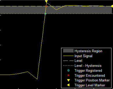
Hysteresis of Trigger Signals
Hysteresis — Specify the hysteresis or noise reject value. This parameter is visible under Settings > Level Settings when you set Type toEdge or Timeout. If the signal jitters inside this range and briefly crosses the trigger level, the scope does not register an event. In the case of an edge trigger with rising polarity, the scope ignores the times that a signal crosses the trigger level within the hysteresis region.
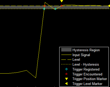
You can reduce the hysteresis region size by decreasing the hysteresis value. In this example, if you set the hysteresis value to 0.07, the scope also considers the second rising edge to be a trigger event.
Delay and Holdoff Properties
Offset the trigger position by a fixed delay, or set the minimum possible time between trigger events using these properties under Settings >Delay/Holdoff.
- Delay (s) — Specify the fixed delay time in seconds by which to offset the trigger position. This parameter controls the amount of time the scope waits after a trigger event occurs before displaying a signal.
- Holdoff (s) — Specify the minimum possible time in seconds between trigger events. This amount of time is used to suppress data acquisition after a valid trigger event has occurred. A trigger holdoff prevents repeated occurrences of a trigger from occurring during the relevant portion of a burst.