Partition Your Model Using Explicit Partitioning - MATLAB & Simulink (original) (raw)
Main Content
When you have a model that is configured for concurrent execution, you can add tasks, create partitions, and map individual tasks to partitions using explicit partitioning. This enables you to execute different parts of your model to different parts of your architecture. For more information, see Implicit and Explicit Partitioning of Models.
Prerequisites for Explicit Partitioning
To use explicit partitioning, you must meet the following prerequisites:
- Set up your model for concurrent execution. For more information, see Configure Your Model for Concurrent Execution.
- Convert all blocks at the root level of your model into one of the following types of blocks.
- Models that are referenced using Model blocks
- Subsystem blocks
- MATLAB® System blocks
- MATLAB Function blocks
- Stateflow® charts
For more information, see Implicit and Explicit Partitioning of Models.
Note
When using referenced models, replicate the model configuration parameters of the top model to the referenced models. Consider using a single configuration reference to use for all of your referenced models. For more information, seeModel Configuration Sets.
- Select the target architecture on which to deploy your model. For more information, see Specify a Target Architecture.
Add Periodic Triggers and Tasks
Add periodic tasks for components in your model that you want to execute periodically. To add aperiodic tasks whose execution is trigger based, see Add Aperiodic Triggers and Tasks.
If you want to explore the effects of increasing the concurrency on your model execution, you can create additional periodic tasks in your model.
- In the Concurrent Execution dialog box, right-click thePeriodic node and select Add task.
A task node appears in the Configuration Execution hierarchy. - Select the task node and enter a name and period for the task, then clickApply.
The task node is renamed to the name you enter. - Optionally, specify a color for the task. The color illustrates the block-to-task mapping. If you do not assign a color, Simulink® chooses a default color. If you enable sample time colors for your model, the software honors the setting.
- Click Apply as necessary.
To create more periodic triggers, click the Add periodic trigger symbol. You can also create multiple periodic triggers with their own trigger sources.
Note
Periodic triggers let you represent multiple periodic interrupt sources such as multiple timers. The periodicity of the trigger is either the base rate of the tasks that the trigger schedules, or the period of the trigger. Data transfers between triggers can only be Ensure Data Integrity Only types. With blocks mapped to periodic triggers, you can only generate code for ert.tlc andgrt.tlc system target files.
To delete tasks and triggers, right-click them in the pane and selectDelete.
When the periodic tasks and trigger configurations are complete, configure the aperiodic (interrupt) tasks as necessary. If you do not need aperiodic tasks, continue to Map Blocks to Tasks, Triggers, and Nodes.
Add Aperiodic Triggers and Tasks
Add aperiodic tasks for components in your model whose execution is interrupt-based. To add periodic tasks whose execution is periodic, see Add Periodic Triggers and Tasks.
- To create an aperiodic trigger, in the Concurrent Execution dialog box, right-click the Concurrent Execution node and click the Add aperiodic trigger symbol.
A node named InterruptNappears in the configuration tree hierarchy, whereNis an integer. - Select Interrupt.
This node represents an aperiodic trigger for your system. - Specify the name of the trigger and configure the aperiodic trigger source. Depending on your deployment target, choose either
Posix Signal (Linux/VxWorks 6.x)orEvent (Windows). For POSIX® signals, specify the signal number to use for delivering the aperiodic event. For Windows® events, specify the name of the event.
- Click Apply.
The software services aperiodic triggers as soon as possible. If you want to process the trigger response using a task:
- Right-click the Interrupt node and select Add task.
A new task node appears under the Interrupt node. - Specify the name of the new task node.
- Optionally, specify a color for the task. The color illustrates the block-to-task mapping. If you do not assign a color, Simulink chooses a default color.
- Click Apply.
To delete tasks and triggers, right-click them in the pane and selectDelete.
Once you have created your tasks and triggers, map your execution components to these tasks. For more information, see Map Blocks to Tasks, Triggers, and Nodes.
Map Blocks to Tasks, Triggers, and Nodes
After you create the tasks and triggers, you can explicitly assign partitions to these execution elements.
- In the Concurrent Execution dialog box, click the Tasks and Mapping node.
The Tasks and Mapping pane appears. If you add aModel block to your model, the new block appears in the table with aselect task entry under it. - If you want to add a task to a block, in the Name column, right-click a task under the block and select Add new entry.
- To assign a task for the entry, click the box in the Name column and select an entry from the list. For example, periodic tasks and an aperiodic trigger are mapped to specific blocks.

The block-to-task mapping symbol appears on the top-left corner of theModel block for periodic tasks or triggers and the top-left corner of the Inport block for aperiodic tasks or triggers.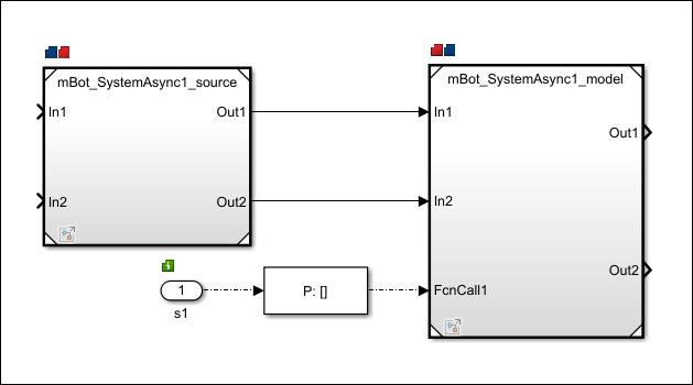
If you assign a Model block to multiple tasks, multiple task symbols are displayed in the top-left corner.
To display the Concurrent Execution dialog box from the block, click the block-to-task mapping symbol. - Click Apply.
Note
- System tasks allow you to perform mapping incrementally. If only one periodic trigger is present, Simulink assigns any Model blocks, subsystem blocks, orMATLAB System blocks that you have not explicitly mapped to a task, trigger, or hardware node to a task created by the system. Simulink creates at most one system task for each rate in the model. If multiple periodic triggers are created, explicitly map the Model block partitions, subsystems, or MATLAB System blocks to a task, trigger, or hardware node.
- Map Model block partitions that contain continuous blocks to the same periodic trigger.
- You can map only Model blocks to hardware nodes. Also, if you map the Model block to a hardware node and the Model block contains multiple periodic sample times, clear the Allow tasks to execute concurrently on target check box in the Solver pane of the Configuration Parameters dialog box.
When the mapping is complete, simulate the model again.