Buildings.Examples.Tutorial.CDL (original) (raw)
Package with examples for how to implement a control sequence using CDL
Information
This package contains examples with step-by-step instructions for how to implement control sequences using the Control Description Language (CDL). The CDL is described atobc.lbl.gov and elementary building blocks are available atBuildings.Controls.OBC.CDL.
The example starts with an open-loop model of a boiler, a simple room and a radiator. In subsequent steps, controllers are added, starting with open loop control and then closed loop control. The tutorial also demonstrates how to add open loop validation tests for the controllers. At the end, you should be able to implement, document and test your own controllers.
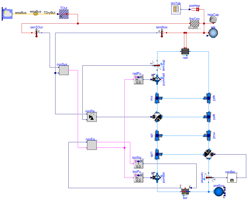
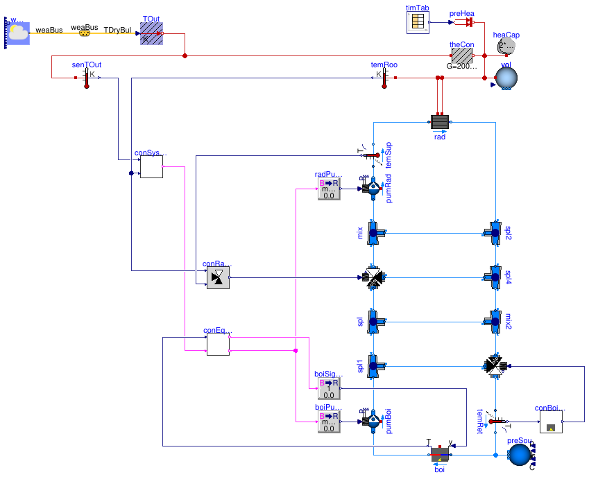
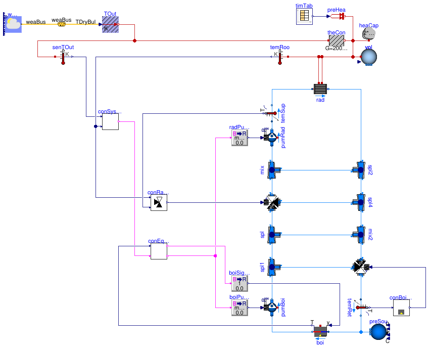
The figure below shows the system architecture and the control charts.
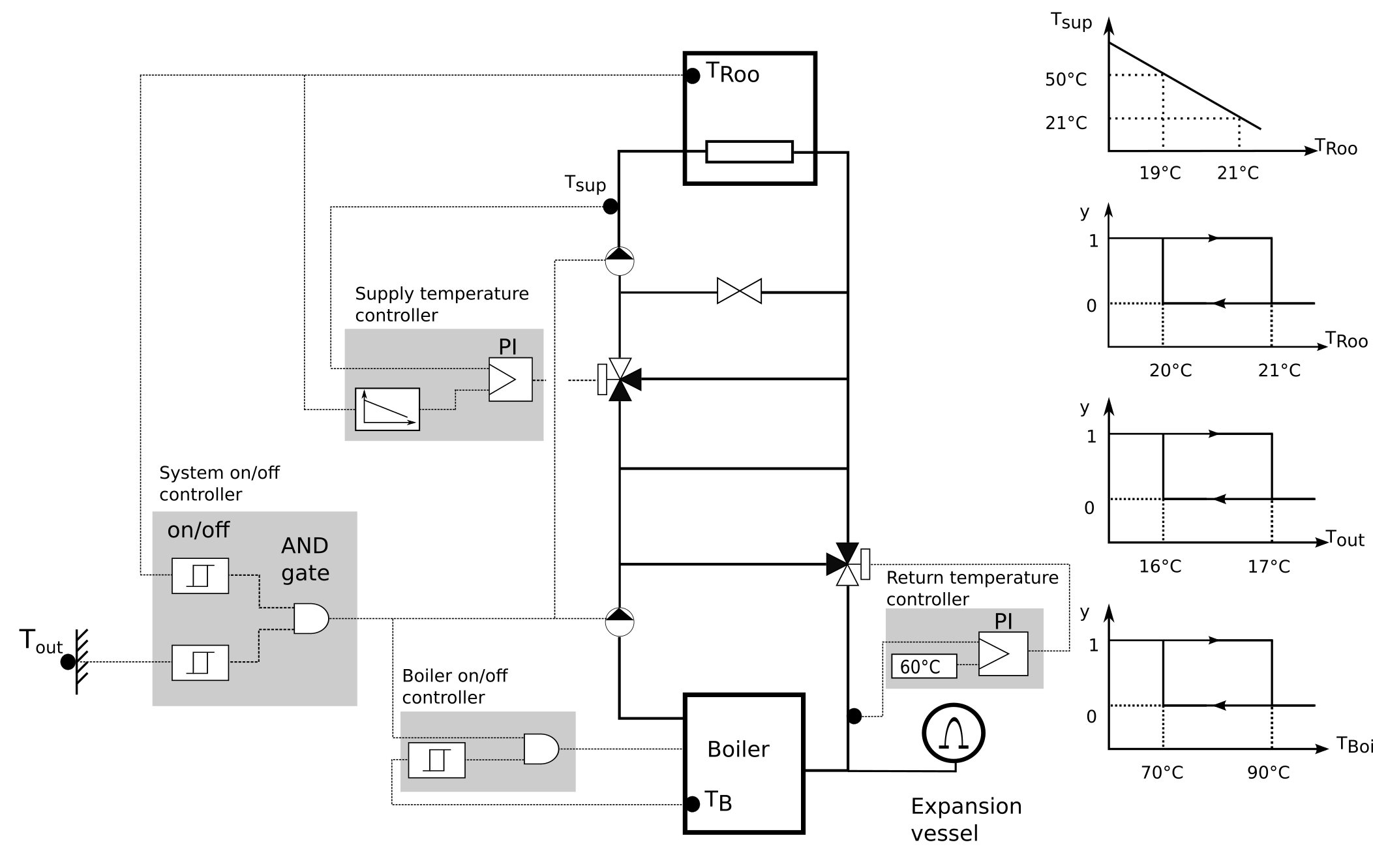
The controls intent is as follows:
- The overall system shall be switched on if the outdoor temperature is below_16_°C and, in addition, the room temperature is below_20_°C. It shall be switched off if either the outdoor temperature is above_17_°C or the room temperature is above_21_°C.
- The boiler shall have on/off control that regulates its temperature between _70_°C and _90_°C.
- The three-way valve at the boiler return shall be modulated with a PI controller to track a return water temperature of _60_°C.
- The heating water supply temperature to the room shall be regulated with a PI controller to be _50_°C if the room temperature is _19_°C, and _21_°C if the room temperature is _21_°C.
To explain the implementation of the controllers for this model, the model has been created in the stages described below.
- InBuildings.Examples.Tutorial.CDL.System1we connected constant control signals to the open loop model that is the starting point for this tutorial.
- InBuildings.Examples.Tutorial.CDL.System2we implemented four distinct controllers, which are all open loop but have the correct control input and output connectors. These controllers will be refined in the next steps. This determines the control architecture.
- InBuildings.Examples.Tutorial.CDL.System3we implemented the controller that regulates the return water temperature to its setpoint.
- InBuildings.Examples.Tutorial.CDL.System4we implemented the controller that switches the boiler on and off.
- InBuildings.Examples.Tutorial.CDL.System5we implemented the controller that switches the whole system on and off.
- InBuildings.Examples.Tutorial.CDL.System6we implemented the controller that tracks the room temperature set point.
Extends from Modelica.Icons.ExamplesPackage (Icon for packages containing runnable examples).
Package Content
| Name | Description |
|---|---|
 System1 System1 |
Open loop model |
| System2 |
Open loop model with control architecture implemented |
| System3 |
Open loop model with boiler return temperature control |
| System4 |
Open loop model with equipment on/off control |
| System5 |
Open loop model with system on/off control |
| System6 |
Closed loop model with all controls implemented |
 Controls Controls |
Package with the controllers used in the tutorial |
 BaseClasses BaseClasses |
Package that contains the model of the HVAC system and the building load |
 Buildings.Examples.Tutorial.CDL.System1
Open loop model
Information
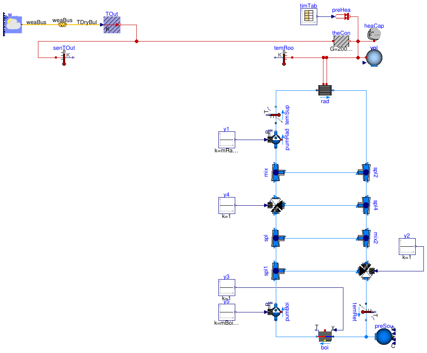
This model extends from the open loop partial modelBuildings.Examples.Tutorial.CDL.BaseClasses.PartialOpenLoop, which implements the HVAC system model and a simple room. In this partial model, the room is modeled as a first order response.
Implementation
To set control inputs, we instantiatedBuildings.Controls.OBC.CDL.Reals.Sources.Constantand connected them to the pumps, the boiler and the valves.
Exercise
Create a model, such as this model, that extends fromBuildings.Examples.Tutorial.CDL.BaseClasses.PartialOpenLoopand adds constant input signals for the valves, pumps and the boiler. Valves should be fully open (y=1), the boiler should be operating (y=1) and the mass flow rates of the pumps should be set to the parameter value ofmRad_flow_nominal and mBoi_flow_nominal.
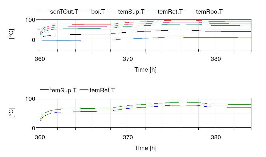
Simulate the model for January 15 to 16 and plot the open loop temperatures as shown below, which corresponds to a start time of 15*24*3600=1296000 seconds and a stop time of 1382400 seconds.
Extends from Buildings.Examples.Tutorial.CDL.BaseClasses.PartialOpenLoop (Partial model with open loop system).
Parameters
| Type | Name | Default | Description |
|---|---|---|---|
| replaceable package MediumA | Air | Medium model for air | |
| replaceable package MediumW | Water | Medium model for water | |
| HeatFlowRate | Q_flow_nominal | 20000 | Nominal heat flow rate of radiator [W] |
| Temperature | TRadSup_nominal | 273.15 + 50 | Radiator nominal supply water temperature [K] |
| Temperature | TRadRet_nominal | 273.15 + 40 | Radiator nominal return water temperature [K] |
| MassFlowRate | mRad_flow_nominal | Q_flow_nominal/4200/(TRadSup... | Radiator nominal mass flow rate [kg/s] |
| Temperature | TBoiSup_nominal | 273.15 + 70 | Boiler nominal supply water temperature [K] |
| Temperature | TBoiRet_min | 273.15 + 60 | Boiler minimum return water temperature [K] |
| MassFlowRate | mBoi_flow_nominal | Q_flow_nominal/4200/(TBoiSup... | Boiler nominal mass flow rate [kg/s] |
| MassFlowRate | mRadVal_flow_nominal | Q_flow_nominal/4200/(TBoiSup... | Radiator nominal mass flow rate [kg/s] |
| Volume | V | 6*10*3 | Room volume [m3] |
| MassFlowRate | mA_flow_nominal | V*1.2*6/3600 | Nominal mass flow rate [kg/s] |
| HeatFlowRate | QRooInt_flow | 4000 | Internal heat gains of the room [W] |
Connectors
| Type | Name | Description |
|---|---|---|
| Bus | weaBus | Weather data bus |
Modelica definition
Buildings.Examples.Tutorial.CDL.System2
Open loop model with control architecture implemented
Information
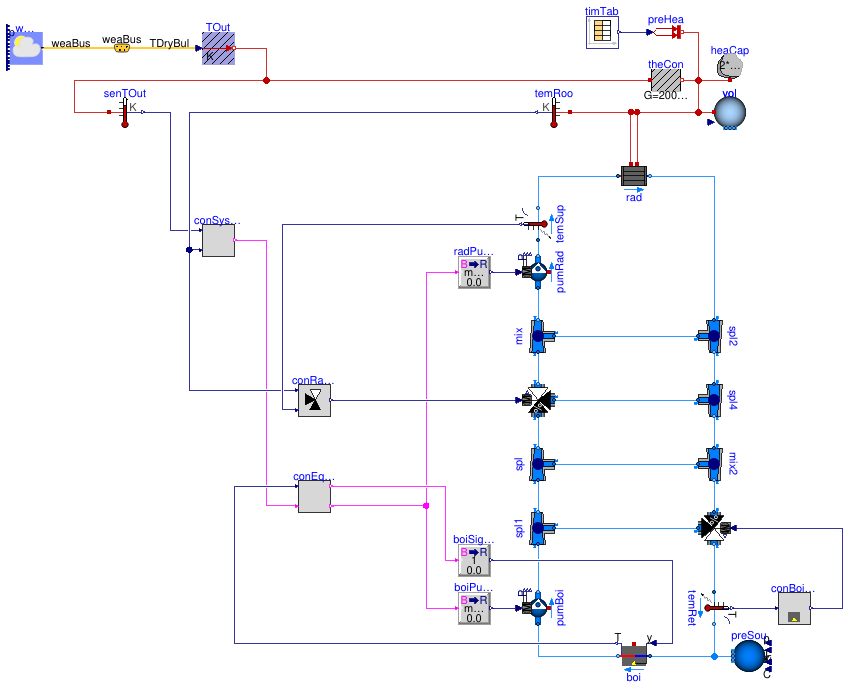
In this step, we added the control architecture. How the control is partitioned into various subcontrollers depends usually on the need to avoid communication over the network and on how control is distributed to different field controllers. Here, we used the four controllers indicated by the shaded background in the figure ofBuildings.Examples.Tutorial.CDL. One controller switches the overall system on and off, one switches the boiler on and off, one tracks the supply water temperature to the room and one tracks the return water temperature that is fed to the boiler.
Implementation
This model was built as follows:
- First, we determined what functionality should be implemented in which controller, and what the inputs and outputs of the controllers are. In this example, we used these controllers:
- Boiler return water controller, with input being the return water temperature
TRetand output being the valve control signalyVal. - Radiator loop temperature controller, with input being the measured supply water temperature
TSup, the measured room air temperatureTRooand output being the valve control signalyVal. - System on/off controller, with inputs being the outdoor temperature
TOutand the room air temperatureTRoo, and output being the system on/off signalonSys. Note that how inputs and outputs are named can simplify usability. For example, we called the outputonSysso that a value oftrueis clearly understood as the system being on. If we had called ity, then it would not have been clear what a value oftruemeans. - Equipment controller, with inputs being the system on/off command and the boiler temperature, and outputs being the pump on/off signal
onPumand the boiler on/off signalonBoi.
- Boiler return water controller, with input being the return water temperature
- To organize our code, we created package that we called
Controls. - Next, we added the open loop controller for the boiler return water temperature. This controller is implemented inBuildings.Examples.Tutorial.CDL.Controls.OpenLoopBoilerReturn. To implement it, we created a Modelica block, and added an input, using aBuildings.Controls.OBC.CDL.Interfaces.RealInput, called it
TRetfor the measured return water temperature, and aBuildings.Controls.OBC.CDL.Interfaces.RealOutputfor the valve control signal, which we calledyVal.
To output the valve control signal, which we set for now to a constant value of 1, we used an instance ofBuildings.Controls.OBC.CDL.Reals.Sources.Constant, set its parameter to 1, and connected it to the output.
At this stage, because the control is open loop, we leave the input of the controller unconnected.
Looking at the Modelica file shows that we also added documentation in aninfosection, adefaultComponentName, as well as graphical elements so that it is easily distinguishable in a schematic diagram. We also added theunitanddisplayUnitattributes.
In the next step of this tutorial, we will provide an actual implementation of the controller. To better distinguish the open loop controller from the closed loop controller, we color the icon of open loop controllers grey, and will change this color to white when we implement the actual control logic. - We did a similar process to add the other three open loop controllers. As before, we added all inputs and outputs, and set the outputs to a constant.
- Lastly, we instantiated these four controllers in the system model. Because the pumps and the boiler take as a control input a real-valued signal, we usedBuildings.Controls.OBC.CDL.Conversions.BooleanToReal to convert between the boolean-valued signal and the real-valued inputs of these components. Whether this conversion is part of the controller or done outside the controller is an individual design decision.
Exercise
Create a model, such as this model. To do so,
- CopyBuildings.Examples.Tutorial.CDL.System1.
- Implement all four open loop controllers.
- Delete the constant control inputs, instantiate the open loop controllers, convert the signal as needed from
BooleantoReal, and connect the control inputs and outputs.
Simulate the system to verify that you get the response shown below. As we have not changed any of the control logic, simulating the system should give the same response as forBuildings.Examples.Tutorial.CDL.System1.
Extends from Buildings.Examples.Tutorial.CDL.BaseClasses.PartialOpenLoop (Partial model with open loop system).
Parameters
| Type | Name | Default | Description |
|---|---|---|---|
| replaceable package MediumA | Air | Medium model for air | |
| replaceable package MediumW | Water | Medium model for water | |
| HeatFlowRate | Q_flow_nominal | 20000 | Nominal heat flow rate of radiator [W] |
| Temperature | TRadSup_nominal | 273.15 + 50 | Radiator nominal supply water temperature [K] |
| Temperature | TRadRet_nominal | 273.15 + 40 | Radiator nominal return water temperature [K] |
| MassFlowRate | mRad_flow_nominal | Q_flow_nominal/4200/(TRadSup... | Radiator nominal mass flow rate [kg/s] |
| Temperature | TBoiSup_nominal | 273.15 + 70 | Boiler nominal supply water temperature [K] |
| Temperature | TBoiRet_min | 273.15 + 60 | Boiler minimum return water temperature [K] |
| MassFlowRate | mBoi_flow_nominal | Q_flow_nominal/4200/(TBoiSup... | Boiler nominal mass flow rate [kg/s] |
| MassFlowRate | mRadVal_flow_nominal | Q_flow_nominal/4200/(TBoiSup... | Radiator nominal mass flow rate [kg/s] |
| Volume | V | 6*10*3 | Room volume [m3] |
| MassFlowRate | mA_flow_nominal | V*1.2*6/3600 | Nominal mass flow rate [kg/s] |
| HeatFlowRate | QRooInt_flow | 4000 | Internal heat gains of the room [W] |
Connectors
| Type | Name | Description |
|---|---|---|
| Bus | weaBus | Weather data bus |
Modelica definition
model System2 extends Buildings.Examples.Tutorial.CDL.BaseClasses.PartialOpenLoop;Controls.OpenLoopBoilerReturn conBoiRet ;Controls.OpenLoopSystemOnOff conSysSta ;Controls.OpenLoopRadiatorSupply conRadSup ;Controls.OpenLoopEquipmentOnOff conEquSta ;Buildings.Controls.OBC.CDL.Conversions.BooleanToReal radPumCon( realTrue=mRad_flow_nominal) ;Buildings.Controls.OBC.CDL.Conversions.BooleanToReal boiPumCon( realTrue=mBoi_flow_nominal) ;Buildings.Controls.OBC.CDL.Conversions.BooleanToReal boiSigCon( realTrue=1) ;equation connect(conSysSta.onSys, conEquSta.onSys);connect(conEquSta.onPum, boiPumCon.u);connect(radPumCon.u, conEquSta.onPum);connect(boiSigCon.u, conEquSta.onBoi);connect(radPumCon.y, pumRad.m_flow_in);connect(boiPumCon.y, pumBoi.m_flow_in);connect(boiSigCon.y, boi.y);connect(conRadSup.yVal, valRad.y);connect(conEquSta.TBoi, boi.T);connect(conSysSta.TOut, senTOut.T);connect(conRadSup.TRoo, temRoo.T);connect(conSysSta.TRoo, temRoo.T);connect(temRet.T, conBoiRet.TRet);connect(conBoiRet.yVal, valBoi.y);connect(temSup.T, conRadSup.TSup);end System2;
Buildings.Examples.Tutorial.CDL.System3
Open loop model with boiler return temperature control
Information
In this step, we added the controller for the boiler return water temperature.
Implementation
This model was built as follows:
- First, we copied the controllerBuildings.Examples.Tutorial.CDL.Controls.OpenLoopBoilerReturnto create the blockBuildings.Examples.Tutorial.CDL.Controls.BoilerReturn.
- In this new block, we used a constant output signalBuildings.Controls.OBC.CDL.Reals.Sources.Constantand a PID controllerBuildings.Controls.OBC.CDL.Reals.PID, which we configured as a PI-controller.
We set the controller logic to reverse action. That is because the tracking error is conventionally computed as the difference between the set point value and the sensed value. In our example, if the return temperature is lower than the set point, i.e., if the tracking error is positive, the valve control signal must tend toward zero, i.e., the valve bypass port must open. That means that the unbounded control signal must tend toward negative values so that the bounded output signal tends toward its minimum value. Binding a positive tracking error to a negative unbounded control signal or to the minimum value of the output signal requires a reverse action logic.
Additionally we set the proportional gain to 0.1 as then, in absence of the integral action, a control error of 10 Kelvin changes the control output by 1. We set the time constant to 120 seconds, which is about the time it takes to open and close a valve. These values give typically good closed loop performance.
As the control error is in Kelvin, which is typically of the order of _1_to 10, there is no need to normalize the control input. (If pressure were used, it would make sense to divide the measured signal and the set point so that the control error is usually of the order of one, which makes tuning easier.) - To allow this controller to be tuned, we exposed at the top-level the parameters for the set point temperature and the control gains.
- While the controllerBuildings.Examples.Tutorial.CDL.Controls.BoilerReturnis very simple, for demonstration purposes we also implemented a validation model for this controller. This is done inBuildings.Examples.Tutorial.CDL.Controls.Validation.BoilerReturn. Such validation models help detect implementation errors which may be difficult to diagnose once the controller is used as part of a larger system model. In our experience, implementing small scale validation tests leads to better code and overall faster development as errors are detected early on when they can be corrected quickly. For more information about how to implement a validation model, see theModelica Buildings Library User Guide.
Exercise
Create a model, such as this model. To do so,
- CopyBuildings.Examples.Tutorial.CDL.System2.
- Implement the controller for the boiler return water temperature.
Make a small unit test to verify that the controller is implemented correctly. - Use this new controller instead of the open loop controller
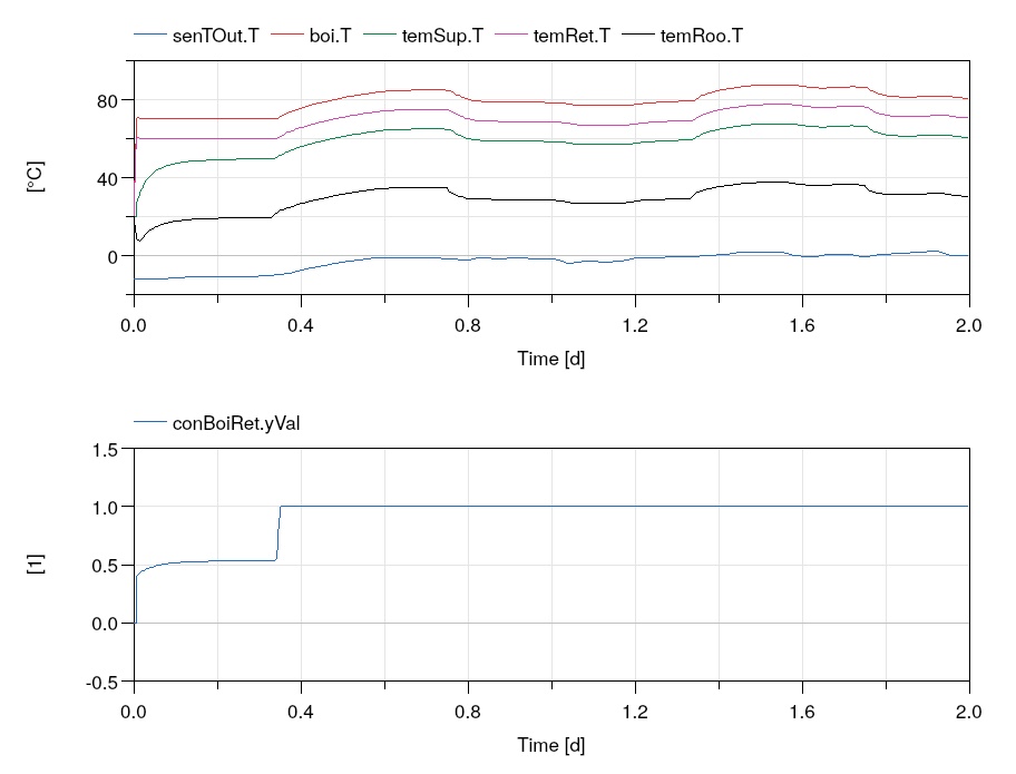
conBoiRet.
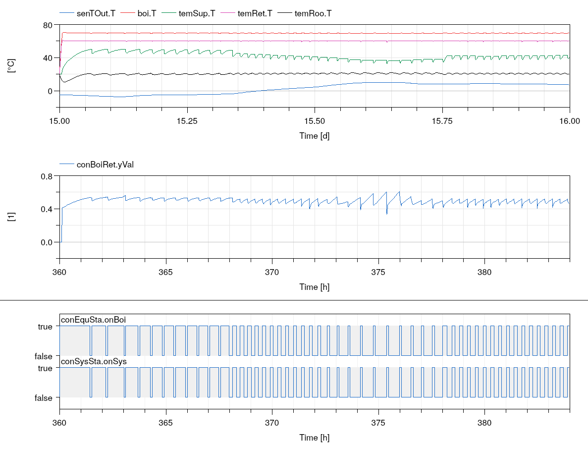
Simulate the system to verify that the valve is controlled to maintain a return water temperature of at least _60_°C as shown below.
Extends from Buildings.Examples.Tutorial.CDL.BaseClasses.PartialOpenLoop (Partial model with open loop system).
Parameters
| Type | Name | Default | Description |
|---|---|---|---|
| replaceable package MediumA | Air | Medium model for air | |
| replaceable package MediumW | Water | Medium model for water | |
| HeatFlowRate | Q_flow_nominal | 20000 | Nominal heat flow rate of radiator [W] |
| Temperature | TRadSup_nominal | 273.15 + 50 | Radiator nominal supply water temperature [K] |
| Temperature | TRadRet_nominal | 273.15 + 40 | Radiator nominal return water temperature [K] |
| MassFlowRate | mRad_flow_nominal | Q_flow_nominal/4200/(TRadSup... | Radiator nominal mass flow rate [kg/s] |
| Temperature | TBoiSup_nominal | 273.15 + 70 | Boiler nominal supply water temperature [K] |
| Temperature | TBoiRet_min | 273.15 + 60 | Boiler minimum return water temperature [K] |
| MassFlowRate | mBoi_flow_nominal | Q_flow_nominal/4200/(TBoiSup... | Boiler nominal mass flow rate [kg/s] |
| MassFlowRate | mRadVal_flow_nominal | Q_flow_nominal/4200/(TBoiSup... | Radiator nominal mass flow rate [kg/s] |
| Volume | V | 6*10*3 | Room volume [m3] |
| MassFlowRate | mA_flow_nominal | V*1.2*6/3600 | Nominal mass flow rate [kg/s] |
| HeatFlowRate | QRooInt_flow | 4000 | Internal heat gains of the room [W] |
Connectors
| Type | Name | Description |
|---|---|---|
| Bus | weaBus | Weather data bus |
Modelica definition
model System3 extends Buildings.Examples.Tutorial.CDL.BaseClasses.PartialOpenLoop;Controls.BoilerReturn conBoiRet ;Controls.OpenLoopSystemOnOff conSysSta ;Controls.OpenLoopRadiatorSupply conRadSup ;Controls.OpenLoopEquipmentOnOff conEquSta ;Buildings.Controls.OBC.CDL.Conversions.BooleanToReal radPumCon( realTrue=mRad_flow_nominal) ;Buildings.Controls.OBC.CDL.Conversions.BooleanToReal boiPumCon( realTrue=mBoi_flow_nominal) ;Buildings.Controls.OBC.CDL.Conversions.BooleanToReal boiSigCon( realTrue=1) ;equation connect(conSysSta.onSys, conEquSta.onSys);connect(conEquSta.onPum, boiPumCon.u);connect(radPumCon.u, conEquSta.onPum);connect(boiSigCon.u, conEquSta.onBoi);connect(radPumCon.y, pumRad.m_flow_in);connect(boiPumCon.y, pumBoi.m_flow_in);connect(boiSigCon.y, boi.y);connect(conRadSup.yVal, valRad.y);connect(conEquSta.TBoi, boi.T);connect(conSysSta.TOut, senTOut.T);connect(conRadSup.TRoo, temRoo.T);connect(conSysSta.TRoo, temRoo.T);connect(temRet.T, conBoiRet.TRet);connect(conBoiRet.yVal, valBoi.y);connect(temSup.T, conRadSup.TSup);end System3;
Buildings.Examples.Tutorial.CDL.System4
Open loop model with equipment on/off control

Information
In this step, we added the controller for the boiler on/off control.
Implementation
This model was built as follows:
- First, we copied the controllerBuildings.Examples.Tutorial.CDL.Controls.OpenLoopEquipmentOnOffto create the blockBuildings.Examples.Tutorial.CDL.Controls.EquipmentOnOff.
- In this new block, we used a hysteresis blockBuildings.Controls.OBC.CDL.Reals.Hysteresis to switch the boiler, and negated its output because the boiler needs to be off if the temperature exceeds the value
uHighof this hysteresis. We also used an instance ofBuildings.Controls.OBC.CDL.Logical.Andto switch the boiler on only if the system control signal is on. Otherwise, the boiler would be kept warm in summer. (Note that in the simulations, the boiler has no heat loss to the ambient and, hence, if the boiler and its circulation pump are switched off, its temperature remains constant. To model heat losses to the ambient, the heat portboi.heatPortwould need to be connected to a model that simulates heat conduction to ambient conditions.) - We also implemented the open loop validationBuildings.Examples.Tutorial.CDL.Controls.Validation.EquipmentOnOffto ensure that the controller is implemented correctly.
Exercise
Create a model, such as this model. To do so,
- CopyBuildings.Examples.Tutorial.CDL.System3.
- Implement the controller for the equipment on/off control.
Make a small unit test to verify that the controller is implemented correctly. - Use this new controller instead of the open loop controller
conEquSta.
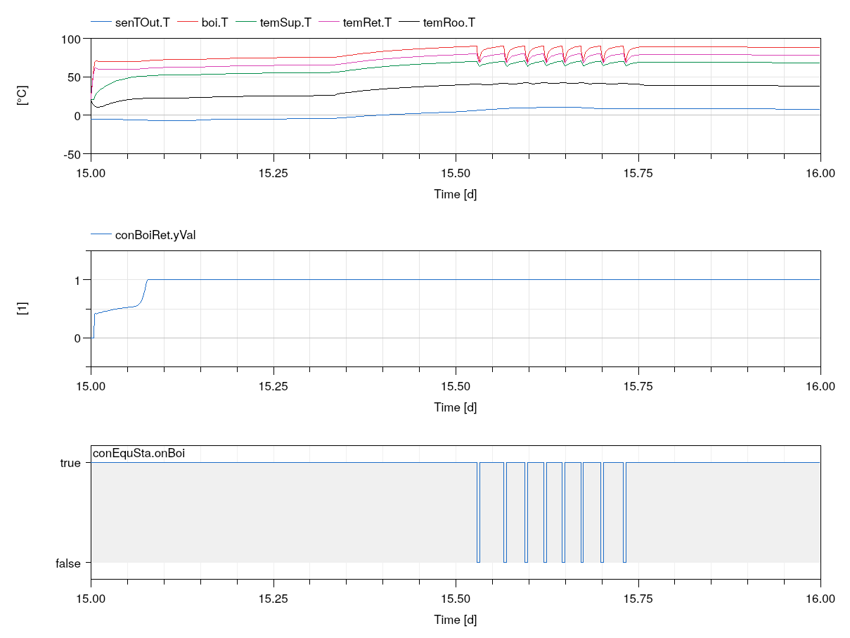
Simulate the system to verify that the valve is controlled to maintain a return water temperature of at least _60_°C, and that the boiler is switched off when the temperature exceeds _90_°C and switched on again if it reaches _70_°C as shown below.
Extends from Buildings.Examples.Tutorial.CDL.BaseClasses.PartialOpenLoop (Partial model with open loop system).
Parameters
| Type | Name | Default | Description |
|---|---|---|---|
| replaceable package MediumA | Air | Medium model for air | |
| replaceable package MediumW | Water | Medium model for water | |
| HeatFlowRate | Q_flow_nominal | 20000 | Nominal heat flow rate of radiator [W] |
| Temperature | TRadSup_nominal | 273.15 + 50 | Radiator nominal supply water temperature [K] |
| Temperature | TRadRet_nominal | 273.15 + 40 | Radiator nominal return water temperature [K] |
| MassFlowRate | mRad_flow_nominal | Q_flow_nominal/4200/(TRadSup... | Radiator nominal mass flow rate [kg/s] |
| Temperature | TBoiSup_nominal | 273.15 + 70 | Boiler nominal supply water temperature [K] |
| Temperature | TBoiRet_min | 273.15 + 60 | Boiler minimum return water temperature [K] |
| MassFlowRate | mBoi_flow_nominal | Q_flow_nominal/4200/(TBoiSup... | Boiler nominal mass flow rate [kg/s] |
| MassFlowRate | mRadVal_flow_nominal | Q_flow_nominal/4200/(TBoiSup... | Radiator nominal mass flow rate [kg/s] |
| Volume | V | 6*10*3 | Room volume [m3] |
| MassFlowRate | mA_flow_nominal | V*1.2*6/3600 | Nominal mass flow rate [kg/s] |
| HeatFlowRate | QRooInt_flow | 4000 | Internal heat gains of the room [W] |
Connectors
| Type | Name | Description |
|---|---|---|
| Bus | weaBus | Weather data bus |
Modelica definition
model System4 extends Buildings.Examples.Tutorial.CDL.BaseClasses.PartialOpenLoop;Controls.BoilerReturn conBoiRet ;Controls.OpenLoopSystemOnOff conSysSta ;Controls.OpenLoopRadiatorSupply conRadSup ;Controls.EquipmentOnOff conEquSta ;Buildings.Controls.OBC.CDL.Conversions.BooleanToReal radPumCon( realTrue=mRad_flow_nominal) ;Buildings.Controls.OBC.CDL.Conversions.BooleanToReal boiPumCon( realTrue=mBoi_flow_nominal) ;Buildings.Controls.OBC.CDL.Conversions.BooleanToReal boiSigCon( realTrue=1) ;equation connect(conSysSta.onSys, conEquSta.onSys);connect(conEquSta.onPum, boiPumCon.u);connect(radPumCon.u, conEquSta.onPum);connect(boiSigCon.u, conEquSta.onBoi);connect(radPumCon.y, pumRad.m_flow_in);connect(boiPumCon.y, pumBoi.m_flow_in);connect(boiSigCon.y, boi.y);connect(conRadSup.yVal, valRad.y);connect(conEquSta.TBoi, boi.T);connect(conSysSta.TOut, senTOut.T);connect(conRadSup.TRoo, temRoo.T);connect(conSysSta.TRoo, temRoo.T);connect(temRet.T, conBoiRet.TRet);connect(conBoiRet.yVal, valBoi.y);connect(temSup.T, conRadSup.TSup);end System4;
Buildings.Examples.Tutorial.CDL.System5
Open loop model with system on/off control
Information
In this step, we added the controller for the system on/off control.
Implementation
This model was built as follows:
- First, we copied the controllerBuildings.Examples.Tutorial.CDL.Controls.OpenLoopSystemOnOffto create the blockBuildings.Examples.Tutorial.CDL.Controls.SystemOnOff.
- In this new block, we implemented the on/off control by using bothBuildings.Controls.OBC.CDL.Reals.SubtractandBuildings.Controls.OBC.CDL.Reals.Hysteresis to determine whether the system should be on, which is the case if both, the outside air temperature and the room air temperature are below a limit. If either is above this limit, plus a deadband, the system is off.
- We also implemented the open loop validationBuildings.Examples.Tutorial.CDL.Controls.Validation.SystemOnOffto ensure that the controller is implemented correctly.
Exercise
Create a model, such as this model. To do so,
- CopyBuildings.Examples.Tutorial.CDL.System4.
- Implement the controller for the system on/off control.
Make a small unit test to verify that the controller is implemented correctly. - Use this new controller instead of the open loop controller
conSysSta.
Simulate the system to verify that the system is switched off if the room temperature exceeeds its set point plus half the dead band. This should yield a plot similar to the one below.
Extends from Buildings.Examples.Tutorial.CDL.BaseClasses.PartialOpenLoop (Partial model with open loop system).
Parameters
| Type | Name | Default | Description |
|---|---|---|---|
| replaceable package MediumA | Air | Medium model for air | |
| replaceable package MediumW | Water | Medium model for water | |
| HeatFlowRate | Q_flow_nominal | 20000 | Nominal heat flow rate of radiator [W] |
| Temperature | TRadSup_nominal | 273.15 + 50 | Radiator nominal supply water temperature [K] |
| Temperature | TRadRet_nominal | 273.15 + 40 | Radiator nominal return water temperature [K] |
| MassFlowRate | mRad_flow_nominal | Q_flow_nominal/4200/(TRadSup... | Radiator nominal mass flow rate [kg/s] |
| Temperature | TBoiSup_nominal | 273.15 + 70 | Boiler nominal supply water temperature [K] |
| Temperature | TBoiRet_min | 273.15 + 60 | Boiler minimum return water temperature [K] |
| MassFlowRate | mBoi_flow_nominal | Q_flow_nominal/4200/(TBoiSup... | Boiler nominal mass flow rate [kg/s] |
| MassFlowRate | mRadVal_flow_nominal | Q_flow_nominal/4200/(TBoiSup... | Radiator nominal mass flow rate [kg/s] |
| Volume | V | 6*10*3 | Room volume [m3] |
| MassFlowRate | mA_flow_nominal | V*1.2*6/3600 | Nominal mass flow rate [kg/s] |
| HeatFlowRate | QRooInt_flow | 4000 | Internal heat gains of the room [W] |
Connectors
| Type | Name | Description |
|---|---|---|
| Bus | weaBus | Weather data bus |
Modelica definition
model System5 extends Buildings.Examples.Tutorial.CDL.BaseClasses.PartialOpenLoop;Controls.BoilerReturn conBoiRet ;Controls.SystemOnOff conSysSta ;Controls.OpenLoopRadiatorSupply conRadSup ;Controls.EquipmentOnOff conEquSta ;Buildings.Controls.OBC.CDL.Conversions.BooleanToReal radPumCon( realTrue=mRad_flow_nominal) ;Buildings.Controls.OBC.CDL.Conversions.BooleanToReal boiPumCon( realTrue=mBoi_flow_nominal) ;Buildings.Controls.OBC.CDL.Conversions.BooleanToReal boiSigCon( realTrue=1) ;equation connect(conSysSta.onSys, conEquSta.onSys);connect(conEquSta.onPum, boiPumCon.u);connect(radPumCon.u, conEquSta.onPum);connect(boiSigCon.u, conEquSta.onBoi);connect(radPumCon.y, pumRad.m_flow_in);connect(boiPumCon.y, pumBoi.m_flow_in);connect(boiSigCon.y, boi.y);connect(conRadSup.yVal, valRad.y);connect(conEquSta.TBoi, boi.T);connect(conSysSta.TOut, senTOut.T);connect(conRadSup.TRoo, temRoo.T);connect(conSysSta.TRoo, temRoo.T);connect(temRet.T, conBoiRet.TRet);connect(conBoiRet.yVal, valBoi.y);connect(temSup.T, conRadSup.TSup);end System5;
Buildings.Examples.Tutorial.CDL.System6
Closed loop model with all controls implemented
Information
In this step, we added the last controller, which is controlling the mixing valve for the radiator supply water temperature.
Implementation
This model was built as follows:
- First, we copied the controllerBuildings.Examples.Tutorial.CDL.Controls.OpenLoopRadiatorSupplyto create the blockBuildings.Examples.Tutorial.CDL.Controls.RadiatorSupply.
- In this new block, we usedBuildings.Controls.OBC.CDL.Reals.Line to compute the set point for the supply water temperature based on the room air temperature. This set point is then used in a PI controllerBuildings.Controls.OBC.CDL.Reals.PID to modulate the mixing valve position in order to track the supply water temperature set point.
- To allow configuring the temperatures and the control gains, we exposed the main parameters of the controller, see Buildings.Examples.Tutorial.CDL.Controls.RadiatorSupply.
- We also implemented the open loop validationBuildings.Examples.Tutorial.CDL.Controls.Validation.RadiatorSupplyto ensure that the controller is implemented correctly.
Exercise
Create a model, such as this model. To do so,
- CopyBuildings.Examples.Tutorial.CDL.System5.
- Implement the controller for the radiator supply water temperature control.
Make a small unit test to verify that the controller is implemented correctly. - Use this new controller instead of the open loop controller
conRadSup.
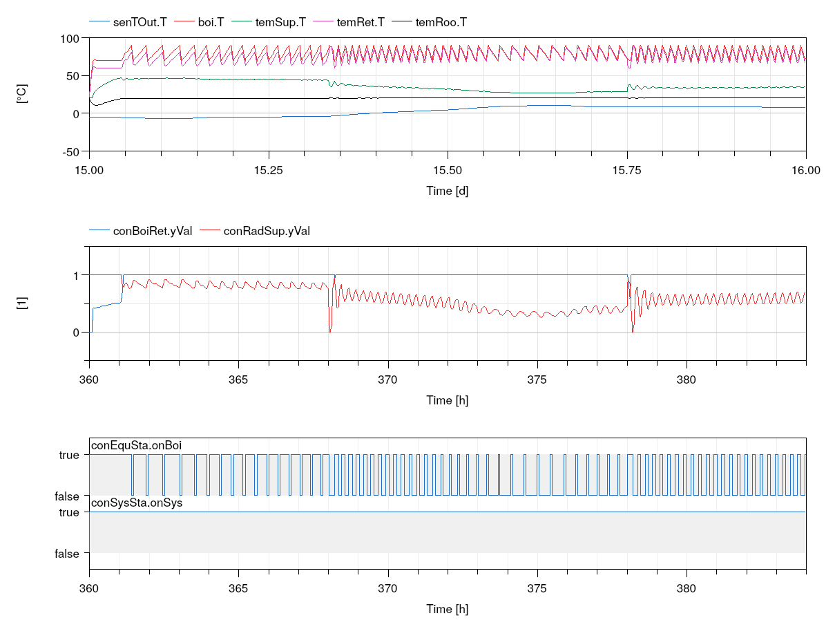
Simulate the system to verify that the mixing valve conRadSup is modulated and the room air temperature temRoo.T is well tracked.
Extends from Buildings.Examples.Tutorial.CDL.BaseClasses.PartialOpenLoop (Partial model with open loop system).
Parameters
| Type | Name | Default | Description |
|---|---|---|---|
| replaceable package MediumA | Air | Medium model for air | |
| replaceable package MediumW | Water | Medium model for water | |
| HeatFlowRate | Q_flow_nominal | 20000 | Nominal heat flow rate of radiator [W] |
| Temperature | TRadSup_nominal | 273.15 + 50 | Radiator nominal supply water temperature [K] |
| Temperature | TRadRet_nominal | 273.15 + 40 | Radiator nominal return water temperature [K] |
| MassFlowRate | mRad_flow_nominal | Q_flow_nominal/4200/(TRadSup... | Radiator nominal mass flow rate [kg/s] |
| Temperature | TBoiSup_nominal | 273.15 + 70 | Boiler nominal supply water temperature [K] |
| Temperature | TBoiRet_min | 273.15 + 60 | Boiler minimum return water temperature [K] |
| MassFlowRate | mBoi_flow_nominal | Q_flow_nominal/4200/(TBoiSup... | Boiler nominal mass flow rate [kg/s] |
| MassFlowRate | mRadVal_flow_nominal | Q_flow_nominal/4200/(TBoiSup... | Radiator nominal mass flow rate [kg/s] |
| Volume | V | 6*10*3 | Room volume [m3] |
| MassFlowRate | mA_flow_nominal | V*1.2*6/3600 | Nominal mass flow rate [kg/s] |
| HeatFlowRate | QRooInt_flow | 4000 | Internal heat gains of the room [W] |
Connectors
| Type | Name | Description |
|---|---|---|
| Bus | weaBus | Weather data bus |
Modelica definition
model System6 extends Buildings.Examples.Tutorial.CDL.BaseClasses.PartialOpenLoop;Controls.BoilerReturn conBoiRet ;Controls.SystemOnOff conSysSta ;Controls.RadiatorSupply conRadSup ;Controls.EquipmentOnOff conEquSta ;Buildings.Controls.OBC.CDL.Conversions.BooleanToReal radPumCon( realTrue=mRad_flow_nominal) ;Buildings.Controls.OBC.CDL.Conversions.BooleanToReal boiPumCon( realTrue=mBoi_flow_nominal) ;Buildings.Controls.OBC.CDL.Conversions.BooleanToReal boiSigCon( realTrue=1) ;equation connect(conSysSta.onSys, conEquSta.onSys);connect(conEquSta.onPum, boiPumCon.u);connect(radPumCon.u, conEquSta.onPum);connect(boiSigCon.u, conEquSta.onBoi);connect(radPumCon.y, pumRad.m_flow_in);connect(boiPumCon.y, pumBoi.m_flow_in);connect(boiSigCon.y, boi.y);connect(conRadSup.yVal, valRad.y);connect(conEquSta.TBoi, boi.T);connect(conSysSta.TOut, senTOut.T);connect(conRadSup.TRoo, temRoo.T);connect(conSysSta.TRoo, temRoo.T);connect(temRet.T, conBoiRet.TRet);connect(conBoiRet.yVal, valBoi.y);connect(temSup.T, conRadSup.TSup);end System6;