Design Filter - Design a digital filter or implement a System object in the Live Editor - MATLAB (original) (raw)
Design a digital filter or implement a System object in the Live Editor
Since R2021b
Description
Design Filter helps you design a digital filter interactively. The task automatically generates MATLAB® code to design a filter using the digitalFilter object. If you have installed DSP System Toolbox™, the task can generate MATLAB code to design and implement a filter using the dsp.FIRFilter and the dsp.SOSFilter objects. These System objects filter streaming signals. (since R2023b)
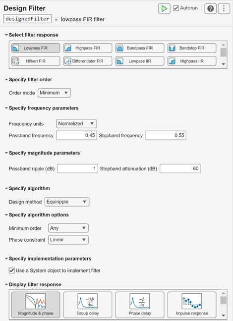
To get started, select a filter response. The task offers controls to specify filter parameters that depend on the type of filter response. The filter parameters that you can specify include:
- Filter order
- Frequency constraints
- Magnitude constraints
- Design method
- Implementation parameters (since R2023b)
Select from a list of display options to visualize the generated filter response and additional filter information. For a detailed description of the filter constraints, design methods, and design method parameters, see the designfilt documentation.
For more information about Live Editor tasks, see Add Interactive Tasks to a Live Script.
Open the Task
To add the Design Filter task to a live script in the MATLAB Editor:
- On the Live Editor tab, select .
- In a code block in the script, type a relevant keyword, such as
designfilt,filter, orlowpass. SelectDesign Filterfrom the suggested command completions.
Examples
Since R2023b
This example shows how to use the Design Filter task in the Live Editor to generate code for a Butterworth highpass IIR digital filter. The task helps you interactively design a digital filter, displays the filter response, and generates code.
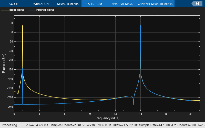
Input Signal
The input is a sinusoidal signal with frequencies at 1 kHz and 15 kHz. Create two dsp.SineWave objects, one to generate the 1 kHz sine wave, and the other to generate the 15 kHz sine wave. Initialize the spectrumAnalyzer object to visualize the spectrum of the input signal and the filtered signal.
Fs = 44.1e3; sine1 = dsp.SineWave(Frequency=1e3,SamplesPerFrame=1024,SampleRate=Fs); sine2 = dsp.SineWave(Frequency=15e3,SamplesPerFrame=1024,SampleRate=Fs); spectrumScope = spectrumAnalyzer(SampleRate=Fs,PlotAsTwoSidedSpectrum=false,... ChannelNames=["Input Signal","Filtered Signal"]);
Design Butterworth Highpass IIR Filter
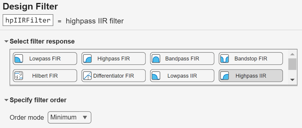
Interactively design a filter to remove the tone at 1 kHz. In the Live Editor tab, expand the Task list and select Design Filter to open the task.
Select a Highpass IIR filter and specify Minimum order mode. Set the filter name as hpIIRFilter.
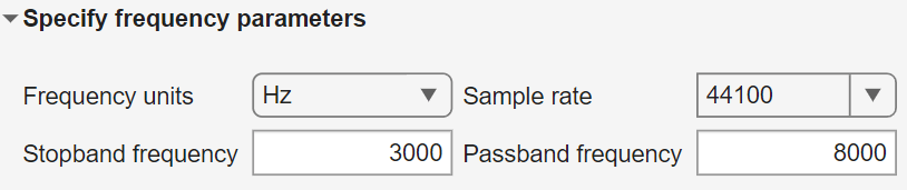
In the Specify frequency parameters section, specify these parameters:
- Frequency units as
Hz - Sample rate to 44.1e3 Hz
- Stopband frequency to 3e3 Hz
- Passband frequency to 8e3 Hz
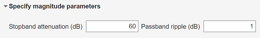
In the Specify magnitude parameters section, set Stopband attenuation (dB) to 60 dB and Passband ripple (dB) to 1 dB.
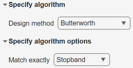
In the Specify algorithm section, select Butterworth for the Design method parameter. Under Specify algorithm options, specify the design to match exactly in the Stopband region.
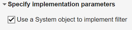
In the Specify implementation parameters section, select the Use a System object to implement filter parameter. This setting generates a dsp.SOSFilter for IIR filter responses.
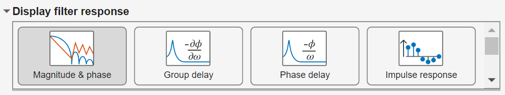
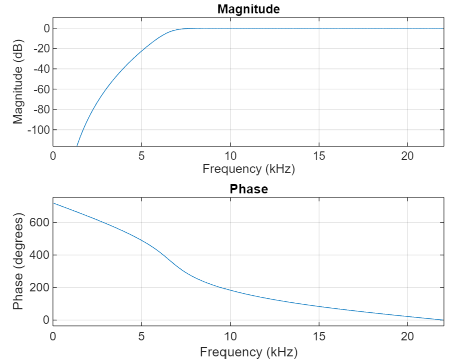
In the Display filter response section, select Magnitude & phase to visualize the designed filter response.
Click the arrow below the Show code section to show the generated code for the designed filter. You can copy and paste the code to the command line to edit the filter design specifications manually.
hpIIRFilter = designfilt('highpassiir',... 'StopbandFrequency',3000,'PassbandFrequency',8000,... 'StopbandAttenuation',60,'PassbandRipple',1,... 'SampleRate',44100,'SystemObject',true)
hpIIRFilter = dsp.SOSFilter with properties:
        Structure: 'Direct form II'
CoefficientSource: 'Property'
        Numerator: [4×3 double]
      Denominator: [4×3 double]
   HasScaleValues: true
      ScaleValues: [0.6823 0.5444 0.4715 0.4397 1]
Show all properties
Stream in 1000 frames of a sinusoidal signal and apply the designed filter to the signal. Visualize the spectrum of the sinusoidal signal and the filtered signal. The designed highpass IIR filter attenuates the 1 kHz tone and passes the 15 kHz tone unaffected.
for i = 1:1000 input = sine1()+sine2(); output = hpIIRFilter(input); spectrumScope(input,output); end
Parameters
Choose the filter response type as one of these:
- Lowpass FIR
- Lowpass IIR
- Highpass FIR
- Highpass IIR
- Bandpass FIR
- Bandpass IIR
- Bandstop FIR
- Bandstop IIR
- Hilbert FIR
- Differentiator FIR
For more information, see resp.
Design a minimum order filter or specify a filter order. Some responses might not have a minimum order design available and will require you to specify a filter order value.
For more information, see Filter Order.
Specify the frequencies at which the designed filter exhibits a desired behavior. Available options depend on filter response type and filter order.
For more information, see Frequency Constraints.
Choose the filter magnitude response behavior at the specified frequency ranges. Available options depend on filter response type, filter order, and frequency constraints.
For more information, see Magnitude Constraints.
Specify the algorithm used to design the filter. Available options depend on filter response type, filter order, and frequency and magnitude constraints. Some design methods have additional options available in the Design options section.
Note
In some design cases, there are model order restrictions. If an even or odd restriction exists for the selected design method and the specified order is not valid, the task reduces the order by one.
For more information, see Design Method.
Since R2023b
Select this parameter to generate a dsp.FIRFilter System object for the FIR filter designs and a dsp.SOSFilter System object for the IIR filter designs.
For more information, see Implementation.
Dependencies
To enable this parameter, you must install DSP System Toolbox and select one of these filter responses:
- Lowpass FIR
- Highpass FIR
- Bandpass FIR (since R2024a)
- Bandstop FIR (since R2024a)
- Lowpass IIR
- Highpass IIR
- Bandpass IIR (since R2024a)
- Bandstop IIR (since R2024a)
Tips
- You can enable or disable the autorun option by selecting or clearing theAutorun checkbox in the top right corner of the task window. If you enable autorun, the current section including the task runs automatically when you make a change.
References
[1] Moody, G.B., and R.G. Mark. "The Impact of the MIT-BIH Arrhythmia Database". IEEE Eng in Med and Biol 20(3):45-50 (May-June 2001): 45-50.
Version History
Introduced in R2021b
When you install DSP System Toolbox, you can select the Use a System object to implement filter parameter in the live task to design and generate a dsp.FIRFilter object for the bandpass and bandstop FIR filter responses, and adsp.SOSFilter object for the bandpass and bandstop IIR filter responses.
The live task includes these features when you install DSP System Toolbox:
- Use a System object to implement filter –– Select this parameter to generate a dsp.FIRFilter object for the lowpass and highpass FIR filter responses, and a dsp.SOSFilter object for the lowpass and highpass IIR filter responses.
IIR least p-normdesign method for the lowpass IIR and the highpass IIR filter responses.- Norm parameter –– Specify the _L_-infinity norm when you select the
IIR least p-normdesign method.