dsp.ChannelSynthesizer - Polyphase FFT synthesis filter bank - MATLAB (original) (raw)
Polyphase FFT synthesis filter bank
Description
The dsp.ChannelSynthesizer System object™ merges multiple narrowband signals into a broadband signal by using an FFT based synthesis filter bank. The filter bank uses a prototype lowpass filter and is implemented using a polyphase structure. You can specify the filter coefficients directly or through design parameters.
To merge multiple narrowband signals into a broadband signal:
- Create the
dsp.ChannelSynthesizerobject and set its properties. - Call the object with arguments, as if it were a function.
To learn more about how System objects work, see What Are System Objects?
Creation
Syntax
Description
`synthesizer` = dsp.ChannelSynthesizer creates a synthesizer object, using the default properties.
synthesizer = dsp.ChannelSynthesizer(`Name=Value`) sets properties using one or more name-value arguments. For example, to set the stopband attenuation as 140, setStopbandAttenuation to 140.
Properties
Unless otherwise indicated, properties are nontunable, which means you cannot change their values after calling the object. Objects lock when you call them, and therelease function unlocks them.
If a property is tunable, you can change its value at any time.
For more information on changing property values, seeSystem Design in MATLAB Using System Objects.
Since R2024a
Interpolation factor L, specified as one of these:
"Number of frequency bands"–– When you change the number of frequency bands, the interpolation factor changes automatically.- Positive integer greater than or equal to the number of frequency bands_M_.
The number of frequency bands equals the number of channels in the input signal. If the interpolation factor L equals the number of frequency bands_M_, then the L/M ratio equals 1, and the synthesizer is known as the critically sampled channel synthesizer.
If L is greater than M, then the_L_/M ratio must be an integer.
Data Types: single | double | int8 | int16 | int32 | int64 | uint8 | uint16 | uint32 | uint64
Filter design parameters or filter coefficients, specified as one of these options:
"Number of taps per band and stopband attenuation"— Specify the filter design parameters through theNumTapsPerBandandStopbandAttenuationproperties."Coefficients"— Specify the filter coefficients directly usingLowpassCoefficients.
Number of filter coefficients each polyphase branch uses, specified as a positive integer. The number of polyphase branches matches the number of frequency bands. The total number of filter coefficients for the prototype lowpass filter is given by product of the number of frequency bands and NumTapsPerBand. For a given stopband attenuation, increasing the number of taps per band narrows the transition width of the filter. As a result, there is more usable bandwidth for each frequency band at the expense of increased computation.
Dependencies
To enable this property, set Specification to"Number of taps per band and stopband attenuation".
Data Types: single | double | int8 | int16 | int32 | int64 | uint8 | uint16 | uint32 | uint64
Stopband attenuation of the lowpass filter, specified as a positive real scalar in dB. This value controls the maximum amount of aliasing from one frequency band to the next. Larger is the stopband attenuation, smaller is the passband ripple.
Dependencies
To enable this property, set Specification to"Number of taps per band and stopband attenuation".
Data Types: single | double
Coefficients of the prototype lowpass filter, specified as a row vector. The default vector of coefficients is obtained usingrcosdesign(0.25,6,8,"sqrt"). There must be at least one coefficient per frequency band. If the length of the lowpass filter is less than the number of frequency bands, the object zero-pads the coefficients.
If you specify complex coefficients, the object designs a prototype filter that is centered at a nonzero frequency, also known as a bandpass filter. The modulated versions of the prototype bandpass filter appear with respect to the prototype filter and are wrapped around the frequency range [−_F_s _F_s].
Tunable: Yes
Dependencies
To enable this property, set Specification to"Coefficients".
Data Types: single | double
Complex Number Support: Yes
Usage
Syntax
Description
[synthOut](#d126e252227) = synthesizer([input](#d126e252156)) merges the narrowband input signals contained as columns in input into broadband signal, synthOut.
Input Arguments
Narrowband signals, specified as a matrix or a 3-D array. Each narrowband signal is stored as a column in the input signal. The number of columns ininput corresponds to the number of frequency bands of the filter bank. If input is three-dimensional, each matrix corresponds to a separate channel. If M is the number of frequency bands, and input is an_Q_-by-M matrix, then the output signal,synthOut, has dimensions _Q×M_-by-1. Ifinput has dimensions_Q_-by-_M_-by-N, thensynthOut has dimensions_Q×M_-by-N.
This object accepts variable-size inputs, that is, once the object is locked, you can change the size of each input channel. The number of channels cannot change.
Data Types: single | double
Complex Number Support: Yes
Output Arguments
Merged broadband signal, returned as a matrix or a 3-D array. If_M_ is the number of frequency bands, andinput is an _Q_-by-M matrix, then the output signal, synthOut, has dimensions_Q×M_-by-1. If input has dimensions_Q_-by-_M_-by-N, thensynthOut has dimensions_Q×M_-by-N.
Data Types: single | double
Complex Number Support: Yes
Object Functions
To use an object function, specify the System object as the first input argument. For example, to release system resources of a System object named obj, use this syntax:
| coeffs | Coefficients of prototype lowpass filter |
|---|---|
| tf | Return transfer function of overall prototype lowpass filter |
| polyphase | Return polyphase matrix |
| step | Run System object algorithm |
|---|---|
| release | Release resources and allow changes to System object property values and input characteristics |
| reset | Reset internal states of System object |
Examples
Channelize and synthesize a sine wave signal with multiple frequencies using an M -channel filter bank.
The M -channel filter bank contains an analysis filter bank section and a synthesis filter bank section. The dsp.Channelizer object implements the analysis filter bank section. The dsp.ChannelSynthesizer object implements the synthesis filter bank section. These objects use an efficient polyphase structure to implement the filter bank. For more details, see Polyphase Implementation under Algorithms on the object reference pages.
Initialization
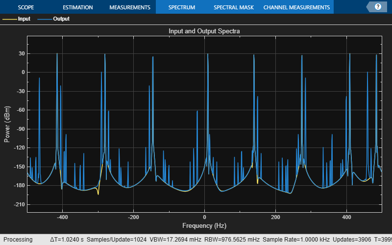
Initialize the dsp.Channelizer and dsp.ChannelSynthesizer System objects. Each object is set up with 8 frequency bands, 8 polyphase branches in each filter, 12 coefficients per polyphase branch, and a stopband attenuation of 140 dB. Use a sine wave with multiple frequencies as the input signal. View the input spectrum and the output spectrum using a spectrum analyzer.
offsets = [-40,-30,-20,10,15,25,35,-15]; sinewave = dsp.SineWave(ComplexOutput=true,Frequency=offsets+(-375:125:500),... SamplesPerFrame=800);
channelizer = dsp.Channelizer(StopbandAttenuation=140); synthesizer = dsp.ChannelSynthesizer(StopbandAttenuation=140); scope = spectrumAnalyzer(ShowLegend=true,... SampleRate=sinewave.SampleRate,... ChannelNames=["Input","Output"],... Title="Input and Output Spectra");
Streaming
Use the channelizer to split the broadband input signal into multiple narrow bands. Then pass the multiple narrowband signals into the synthesizer, which merges these signals to form the broadband signal. Compare the spectra of the input and output signals. The input and output spectra match very closely.
for i = 1:5000 x = sum(sinewave(),2); y = channelizer(x); v = synthesizer(y); scope(x,v) end
Since R2024a
Synthesize a series of four stereo signals into a broadband signal by using the dsp.ChannelSynthesizer object. At the receiving end, split this broadband signal back into the individual narrowband signals by using the dsp.Channelizer object.
Increase the oversampling ratio of channel synthesizer to 4. Inspect the effect on the spectrum of the broadband signal.
Initialization
The audio signals are four stereo signals.
FunkyDrums.mp3SoftGuitar.oggRockDrums.mp3RockGuitar.wav
Each signal is of the size 1024-by-2 samples. The two columns (channels) represent the left channel and the right channel of the stereo signal. Read the signals using the dsp.AudioFileReader object.
af1 = dsp.AudioFileReader(Filename="FunkyDrums.mp3",SamplesPerFrame=1024); af2 = dsp.AudioFileReader(Filename="SoftGuitar.ogg",SamplesPerFrame=1024); af3 = dsp.AudioFileReader(Filename="RockDrums.mp3",SamplesPerFrame=1024); af4 = dsp.AudioFileReader(Filename="RockGuitar.wav",SamplesPerFrame=1024);
The stereo2complex function converts each signal into complex signals. The first column in the signal forms the real part of the complex signal, and the second column in the signal forms the imaginary part of the complex signal.
function y = stereo2complex(u) y = complex(u(:,1),u(:,2)); end
Specify the number of frequency bands M to 4, which is the same as the number of audio files. Specify the decimation factor D of the channelizer to 4 and the interpolation factor I of the channel synthesizer to 4.
Specify the number of taps per band to 48 and the stopband attenuation to 120 dB.
Initialize the dsp.ChannelSynthesizer and dsp.Channelizer objects with the above parameters. The L/M ratio in the channel synthesizer is 4/4, or 1, making it a critically sampled channel synthesizer. The M/D ratio in the channelizer is 4/4, or 1, making it a maximally decimated channelizer.
synthesizer = dsp.ChannelSynthesizer(NumTapsPerBand=48,... StopbandAttenuation=120,InterpolationFactor=I)
synthesizer = dsp.ChannelSynthesizer with properties:
InterpolationFactor: 4
      Specification: 'Number of taps per band and stopband attenuation'
     NumTapsPerBand: 48
StopbandAttenuation: 120
channelizer = dsp.Channelizer(NumFrequencyBands=M,... DecimationFactor=D,NumTapsPerBand=NTPB,StopbandAttenuation=Astop)
channelizer = dsp.Channelizer with properties:
Main NumFrequencyBands: 4 DecimationFactor: 4 Specification: 'Number of taps per band and stopband attenuation' NumTapsPerBand: 48 StopbandAttenuation: 120
Show all properties
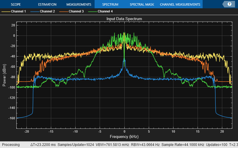
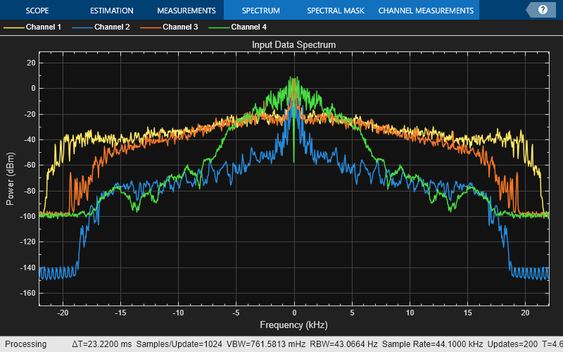
Set up the spectrumAnalyzer objects to visualize the input spectrum, multiplexed broadband spectrum, and the spectrum of the individual channelized audio files.
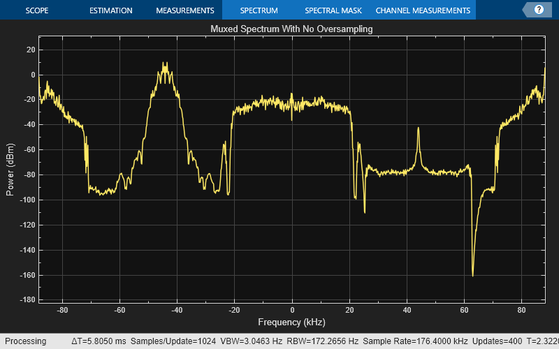
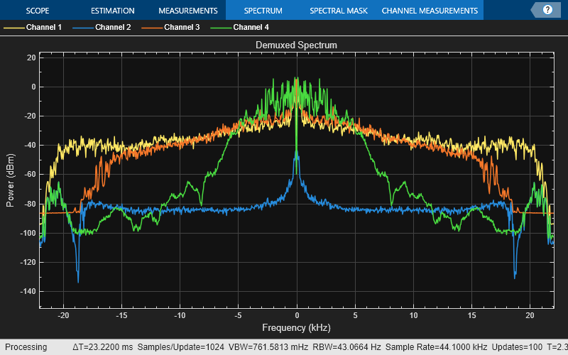
inputDataSpectrum = spectrumAnalyzer(SampleRate=44100,... Position=[4 880 800 500],Title="Input Data Spectrum"); muxedSpectrum = spectrumAnalyzer(SampleRate=I44100,... Position=[810 880 800 500],Title="Muxed Spectrum With No Oversampling"); channelizedSpectrum = spectrumAnalyzer(SampleRate=I/D44100,... Position=[1620 880 800 500],Title="Demuxed Spectrum");
Streaming
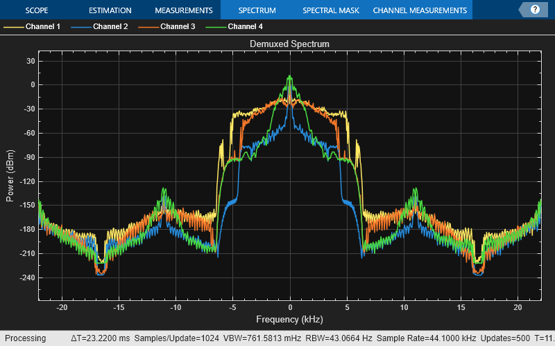
Stream in the four audio files. Convert the signals into complex signals and multiplex them to form a 1024-by-4 matrix u. The dsp.ChannelSynthesizer object synthesizes these four signals into a single broadband signal umuxed. The dsp.Channelizer object splits this broadband signal back into narrow subbands. Each column in the channelizer output represents a narrowband signal.
Visualize the spectrum of the input signal, multiplexed broadband signal, and the individual channelized audio files in the spectrum analyzer. You can see that the multiplexed broadband signal spectrum is critically sampled and that there is no separation between the narrow bands in the spectrum.
for idx = 1:100 u1 = af1(); u2 = af2(); u3 = af3(); u4 = af4(); u = [stereo2complex(u1) stereo2complex(u2) stereo2complex(u3) stereo2complex(u4)]; umuxed = synthesizer(u); uchannelized = channelizer(umuxed); inputDataSpectrum(u); muxedSpectrum(umuxed); channelizedSpectrum(uchannelized); end
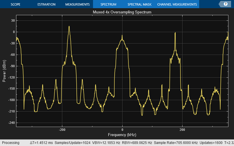
Increasing Oversampling Ratio of Channel Synthesizer
To increase the separation between the individual bands in the multiplexed spectrum, increase the interpolation factor L to 16. This value increases the oversampling ratio L/M of the channel synthesizer to 16/4, or 4.
Rerun the simulation with the new L/M ratio. You can see that the there is more frequency separation now between the individual narrowbands in the multiplexed spectrum.
I = 16; synthesizer = dsp.ChannelSynthesizer(NumTapsPerBand=48,... StopbandAttenuation=120,InterpolationFactor=I); muxed4xSpectrum = spectrumAnalyzer(SampleRate=I*44100,... Position=[810 880 800 500],Title="Muxed 4x Oversampling Spectrum"); for idx = 1:100 u1 = af1(); u2 = af2(); u3 = af3(); u4 = af4(); u = [stereo2complex(u1) stereo2complex(u2) stereo2complex(u3) stereo2complex(u4)]; umuxed = synthesizer(u); uchannelized = channelizer(umuxed); inputDataSpectrum(u); muxed4xSpectrum(umuxed); channelizedSpectrum(uchannelized); end
More About
The synthesis filter bank consists of a set of parallel bandpass filters that merge multiple input narrowband signals,_y0_[_m_],_y1_[_m_], … , _yM-1_[_m_] into a single broadband signal, _v_[n_]. The input narrowband signals are in the baseband. Each narrowband signal is interpolated to a higher sampling rate by using the upsampler, and then filtered by the lowpass filter. A complex exponential that follows the lowpass filter centers the baseband signal around_wk.
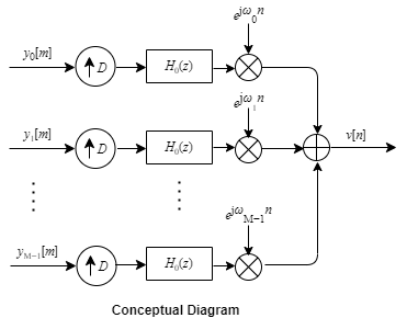
To implement the synthesis filter bank efficiently, the synthesizer uses a prototype lowpass filter. This filter has an impulse response of_h_[_n_], a normalized two-sided bandwidth of 2π/M, and a cutoff frequency of π/M. M is the number of frequency bands, that is, the branches of the synthesis filter bank. This value corresponds to the FFT length that the filter bank uses.M can be high, in the order of 2048 or more. The stopband attenuation determines the minimum level of interference (aliasing) from one frequency band to another. The passband ripple must be small so that the input signal is not distorted in the passband.
The prototype lowpass filter models the first branch of the filter bank. The other_M_ – 1 branches are modeled by filters that are modulated versions of the prototype filter. The modulation factor is given by ejwkn, wk=2πk/M, k=0,1,...,M−1.
The output of each bandpass filter forms a specific portion of the broadband signal. The output of all the branches are added to form the broadband signal,_v_[_n_].
Algorithms
The synthesis filter bank can be implemented efficiently using the polyphase structure.
To derive the polyphase structure, start with the transfer function of the prototype lowpass filter.
N + 1 is the length of the prototype filter.
You can rearrange this equation as follows:
L is the number of polyphase components and equals the interpolation factor.
You can write this equation as:
_E_0(z L),_E_1(z L), … ,E _L_−1(z L) are polyphase components of the prototype lowpass filter,_H_0(z).
The other filters in the filter bank,H k(z), where k = 1, … , M − 1, are modulated versions of the prototype filter,_H_0(z).
You can write the transfer function of the k_th modulated bandpass filter as Hk(z)=H0(zejwk). Replacing z with_zejwk,
N + 1 is the length of the _k_th filter.
In polyphase form, the equation is as follows:
For all M channels in the filter bank, the MIMO transfer function,H(z), is given by:
Here is the multirate noble identity for interpolation:

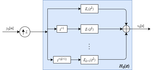
For illustration, consider the first branch of the filter bank that contains the lowpass filter.

Replace H0(z) with its polyphase representation.
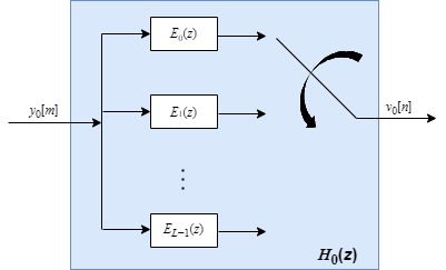
After applying the noble identity for interpolation, you can replace the delays, interpolation factor, and the adder with a commutator switch.
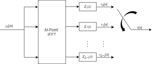
For all the M channels in the filter bank, the MIMO transfer function,H(z), is given by:
The matrix on the left is an IDFT matrix. With the IDFT matrix, the efficient implementation of the lowpass prototype based filter bank looks like the following.
References
[1] Harris, Fredric J, Multirate Signal Processing for Communication Systems, Prentice Hall PTR, 2004.
[2] Harris, F.J., Chris Dick, Michael Rice. "Digital Receivers and Transmitters Using Polyphase Filter Banks for Wireless Communications." IEEE Transactions on microwave theory and techniques. Vol. 51, Number 4, April 2003.
Extended Capabilities
Version History
Introduced in R2016b
Use the new InterpolationFactor property to specify an interpolation factor L that is greater than or equal to the number of frequency bands M. If L > M, then the ratio L/M must be an integer and the synthesizer is known as an oversampled channel synthesizer.