dsp.CICCompensationInterpolator - Compensate for CIC interpolation filter using FIR interpolator - MATLAB (original) (raw)
Compensate for CIC interpolation filter using FIR interpolator
Description
You can compensate for the shortcomings of a CIC interpolator, namely its passband droop and wide transition region, by preceding it with a compensation interpolator. This System object™ lets you design and use such a filter.
To compensate for the shortcomings of a CIC filter using an FIR interpolator:
- Create the
dsp.CICCompensationInterpolatorobject and set its properties. - Call the object with arguments, as if it were a function.
To learn more about how System objects work, see What Are System Objects?
Creation
Syntax
Description
`ciccompint` = dsp.CICCompensationInterpolator returns a System object, ciccompint, that applies an FIR interpolator to each channel of an input signal. Using the properties of the object, the interpolation filter can be designed to compensate for a subsequent CIC filter.
`ciccompint` = dsp.CICCompensationInterpolator(`interp`) returns a CIC compensation interpolator System object, ciccompint, with theInterpolationFactor property set tointerp.
`ciccompint` = dsp.CICCompensationInterpolator(`cic`) returns a CIC compensation interpolator System object, ciccompint, with theCICRateChangeFactor, CICNumSections, andCICDifferentialDelay properties specified in thedsp.CICInterpolator System objectcic.
`ciccompint` = dsp.CICCompensationInterpolator(`cic`,`interp`) returns a CIC compensation interpolator System object, ciccompint, with theCICRateChangeFactor, CICNumSections, andCICDifferentialDelay properties specified in thedsp.CICInterpolator System objectcic, and the InterpolationFactor property set tointerp.
`ciccompint` = dsp.CICCompensationInterpolator(___,`Name=Value`) sets properties using one or more name-value arguments. For example, to specify the rate-change factor of the CIC filter being compensated as 8, set CICRateChangeFactor as 8.
Properties
Unless otherwise indicated, properties are nontunable, which means you cannot change their values after calling the object. Objects lock when you call them, and therelease function unlocks them.
If a property is tunable, you can change its value at any time.
For more information on changing property values, seeSystem Design in MATLAB Using System Objects.
Specify the rate-change factor of the CIC filter being compensated as a positive integer scalar. The default is 2.
Data Types: single | double | int8 | int16 | int32 | int64 | uint8 | uint16 | uint32 | uint64
Specify the number of sections of the CIC filter being compensated as a positive integer scalar.
Data Types: single | double | int8 | int16 | int32 | int64 | uint8 | uint16 | uint32 | uint64
Specify the differential delay of the CIC filter being compensated as a positive integer scalar.
Data Types: single | double | int8 | int16 | int32 | int64 | uint8 | uint16 | uint32 | uint64
Specify the interpolation factor of the compensator System object as a positive integer scalar.
Data Types: single | double | int8 | int16 | int32 | int64 | uint8 | uint16 | uint32 | uint64
Since R2024a
Option to set frequencies in normalized units, specified as one of these values:
true–– The passband frequency Fpass and stopband frequency Fstop must be in the normalized frequency units and must be in the range Fpass <Fstop < 1.0.
When you set theNormalizedFrequencyproperty totruewhile creating the object and you do not set the passband and stopband frequencies, the object automatically sets the default values to normalized frequency units using the default sample rate of 600 kHz.
ciccompint = dsp.CICCompensationInterpolator(NormalizedFrequency=true)
ciccompint =
dsp.CICCompensationInterpolator with properties:
  CICRateChangeFactor: 2
       CICNumSections: 2
 CICDifferentialDelay: 1
  InterpolationFactor: 2
  NormalizedFrequency: true
DesignForMinimumOrder: true
    PassbandFrequency: 0.1667
    StopbandFrequency: 0.6667
       PassbandRipple: 0.1000
  StopbandAttenuation: 60
When you set the NormalizedFrequency property totrue after you create the object, you must specify the passband and stopband frequencies in normalized units before you run the object algorithm.
ciccompint = dsp.CICCompensationInterpolator
ciccompint =
dsp.CICCompensationInterpolator with properties:
CICRateChangeFactor: 2
CICNumSections: 2
CICDifferentialDelay: 1
InterpolationFactor: 2
NormalizedFrequency: false
DesignForMinimumOrder: true
PassbandFrequency: 100000
StopbandFrequency: 400000
PassbandRipple: 0.1000
StopbandAttenuation: 60
SampleRate: 600000
To specify the normalized frequency value, setNormalizedFrequency to true and manually convert the frequency value in Hz to the normalized value using the input sample rate in Hz. For example, if the input sample rate Fs is 600 kHz, the corresponding passband frequency value in normalized units is_Fpass_Hz/Fs and the corresponding stopband frequency in normalized units is_Fstop_Hz/Fs.
ciccompint = dsp.CICCompensationInterpolator;
ciccompint.NormalizedFrequency = true;
ciccompint.PassbandFrequency = 100000/600000;
ciccompint.StopbandFrequency = 400000/600000
ciccompint =
dsp.CICCompensationInterpolator with properties:
CICRateChangeFactor: 2
CICNumSections: 2
CICDifferentialDelay: 1
InterpolationFactor: 2
NormalizedFrequency: true
DesignForMinimumOrder: true
PassbandFrequency: 0.1667
StopbandFrequency: 0.6667
PassbandRipple: 0.1000
StopbandAttenuation: 60
false–– The passband and stopband frequency values are in Hz. You can specify the input sample rate through theSampleRateproperty.
Data Types: logical
Specify whether to design a filter of minimum order or a filter of specified order as a logical scalar. The default is true, which corresponds to a filter of minimum order.
Specify the order of the interpolation compensator filter as a positive integer scalar.
Dependencies
This property applies only when you set the DesignForMinimumOrder property to false.
Data Types: single | double | int8 | int16 | int32 | int64 | uint8 | uint16 | uint32 | uint64
Passband edge frequency Fpass, specified as a positive real scalar in Hz or in normalized frequency units (since R2024a).
If you set theNormalizedFrequency property to:
false–– The value of the passband frequency is in Hz and must be in the range Fpass < Fstop <Fs, where Fstop is the stopband frequency and Fs is the input sample rate.true–– The value of the passband frequency is in normalized frequency units and must be in the range Fpass <Fstop <1.0.
When you set theNormalizedFrequencyproperty totruewhile creating the object and you do not set the passband frequency, the object automatically sets the default passband frequency to normalized frequency units using the default sample rate of 600 kHz.
ciccompint = dsp.CICCompensationInterpolator(NormalizedFrequency=true)
ciccompint =
dsp.CICCompensationInterpolator with properties:
CICRateChangeFactor: 2
CICNumSections: 2
CICDifferentialDelay: 1
InterpolationFactor: 2
NormalizedFrequency: true
DesignForMinimumOrder: true
PassbandFrequency: 0.1667
StopbandFrequency: 0.6667
PassbandRipple: 0.1000
StopbandAttenuation: 60
When you set the NormalizedFrequency property totrue after you create the object, you must specify the passband frequency in normalized units before you run the object algorithm.
ciccompint = dsp.CICCompensationInterpolator
ciccompint =
dsp.CICCompensationInterpolator with properties:
CICRateChangeFactor: 2
CICNumSections: 2
CICDifferentialDelay: 1
InterpolationFactor: 2
NormalizedFrequency: false
DesignForMinimumOrder: true
PassbandFrequency: 100000
StopbandFrequency: 400000
PassbandRipple: 0.1000
StopbandAttenuation: 60
SampleRate: 600000
To specify the normalized frequency value, setNormalizedFrequency to true and manually convert the frequency value in Hz to the normalized value using the input sample rate in Hz. For example, if the input sample rate Fs is 600 kHz, the corresponding passband frequency value in normalized units is_Fpass_Hz/Fs.
ciccompint.NormalizedFrequency = true;
ciccompint.PassbandFrequency = 100000/600000
ciccompint =
dsp.CICCompensationInterpolator with properties:
CICRateChangeFactor: 2
CICNumSections: 2
CICDifferentialDelay: 1
InterpolationFactor: 2
NormalizedFrequency: true
DesignForMinimumOrder: true
PassbandFrequency: 0.1667
StopbandFrequency: 400000
PassbandRipple: 0.1000
StopbandAttenuation: 60
(since R2024a)
Data Types: single | double | int8 | int16 | int32 | int64 | uint8 | uint16 | uint32 | uint64
Stopband edge frequency Fstop, specified as a positive real scalar in Hz or in normalized frequency units (since R2024a).
If you set theNormalizedFrequency property to:
false–– The value of the stopband frequency is in Hz and must be in the range Fpass < Fstop <Fs, where Fpass is the passband frequency and Fs is the input sample rate.true–– The value of the stopband frequency is in normalized frequency units and must be in the range Fpass <Fstop <1.0.
When you set theNormalizedFrequencyproperty totruewhile creating the object and you do not set the stopband frequency, the object automatically sets the default stopband frequency to normalized frequency units using the default sample rate of 600 kHz.
ciccompint = dsp.CICCompensationInterpolator(NormalizedFrequency=true)
ciccompint =
dsp.CICCompensationInterpolator with properties:
CICRateChangeFactor: 2
CICNumSections: 2
CICDifferentialDelay: 1
InterpolationFactor: 2
NormalizedFrequency: true
DesignForMinimumOrder: true
PassbandFrequency: 0.1667
StopbandFrequency: 0.6667
PassbandRipple: 0.1000
StopbandAttenuation: 60
When you set the NormalizedFrequency property totrue after you create the object, you must specify the passband frequency in normalized units before you run the object algorithm.
ciccompint = dsp.CICCompensationInterpolator
ciccompint =
dsp.CICCompensationInterpolator with properties:
CICRateChangeFactor: 2
CICNumSections: 2
CICDifferentialDelay: 1
InterpolationFactor: 2
NormalizedFrequency: false
DesignForMinimumOrder: true
PassbandFrequency: 100000
StopbandFrequency: 400000
PassbandRipple: 0.1000
StopbandAttenuation: 60
SampleRate: 600000
To specify the normalized frequency value, setNormalizedFrequency to true and manually convert the frequency value in Hz to the normalized value using the input sample rate in Hz. For example, if the input sample rate Fs is 600 kHz, the corresponding stopband frequency value in normalized units is_Fstop_Hz/Fs.
ciccompint.NormalizedFrequency = true;
ciccompint.StopbandFrequency = 400000/600000
ciccompint =
dsp.CICCompensationInterpolator with properties:
CICRateChangeFactor: 2
CICNumSections: 2
CICDifferentialDelay: 1
InterpolationFactor: 2
NormalizedFrequency: true
DesignForMinimumOrder: true
PassbandFrequency: 100000
StopbandFrequency: 0.6667
PassbandRipple: 0.1000
StopbandAttenuation: 60
(since R2024a)
Data Types: single | double | int8 | int16 | int32 | int64 | uint8 | uint16 | uint32 | uint64
Specify the filter passband ripple as a positive real scalar expressed in decibels.
Data Types: single | double | int8 | int16 | int32 | int64 | uint8 | uint16 | uint32 | uint64
Specify the filter stopband attenuation as a positive real scalar expressed in decibels.
Data Types: single | double | int8 | int16 | int32 | int64 | uint8 | uint16 | uint32 | uint64
Specify the input sample rate as a positive real scalar expressed in Hz.
Dependencies
To enable this property, set the NormalizedFrequency property to false.
Data Types: single | double
Fixed-Point Properties
Rounding method for output fixed-point operations, specified as a character vector. For more information on the rounding modes, see Precision and Range.
Word and fraction lengths of coefficients, specified as a signed or unsignednumerictype object. The default,numerictype(1,16) corresponds to a signed numeric type object with 16-bit coefficients and a fraction length determined based on the coefficient values, to give the best possible precision.
This property is not tunable.
Word length of the output is same as the word length of the input. Fraction length of the output is computed such that the entire dynamic range of the output can be represented without overflow. For details on how the fraction length of the output is computed, see Fixed-Point Precision Rules for Avoiding Overflow in FIR Filters.
Usage
Syntax
Description
[y](#d126e256223) = ciccompint([x](#d126e256154)) outputs the upsampled and filtered values, y, of the input signal,x.
Input Arguments
Data input, specified as a vector or a matrix. The System object treats a_Ki_ × N input matrix as N independent channels, interpolating each channel over the first dimension.
This object does not support complex unsigned fixed-point data.
Data Types: single | double | int8 | int16 | int32 | int64 | uint8 | uint16 | uint32 | uint64 | fi
Complex Number Support: Yes
Output Arguments
Upsampled and filtered signal, returned as a vector or matrix. For a_Ki_ × N input matrix, the result is a_Ko_ × N output matrix, where_Ko_ = Ki × L and L is the interpolation factor.
Data Types: single | double | int8 | int16 | int32 | int64 | uint8 | uint16 | uint32 | uint64 | fi
Complex Number Support: Yes
Object Functions
To use an object function, specify the System object as the first input argument. For example, to release system resources of a System object named obj, use this syntax:
| freqz | Frequency response of discrete-time filter System object |
|---|---|
| freqzmr | Compute DTFT approximation of impulse response of multirate or single-rate filter |
| filterAnalyzer | Analyze filters with Filter Analyzer app |
| info | Information about filter System object |
| cost | Estimate cost of implementing filter System object |
| coeffs | Returns the filter System object coefficients in a structure |
| polyphase | Polyphase decomposition of multirate filter |
| outputDelay | Determine output delay of single-rate or multirate filter |
| step | Run System object algorithm |
|---|---|
| release | Release resources and allow changes to System object property values and input characteristics |
| reset | Reset internal states of System object |
Examples
Create a dsp.CICCompensationDecimator object with default settings. While creating the object, set the NormalizedFrequency property to true so that the passband and the stopband frequencies are in normalized frequency units.
CICCompInterp = dsp.CICCompensationInterpolator(... NormalizedFrequency=true)
CICCompInterp = dsp.CICCompensationInterpolator with properties:
CICRateChangeFactor: 2
CICNumSections: 2
CICDifferentialDelay: 1
InterpolationFactor: 2
NormalizedFrequency: true
DesignForMinimumOrder: true
PassbandFrequency: 0.1667
StopbandFrequency: 0.6667
PassbandRipple: 0.1000
StopbandAttenuation: 60Show all properties
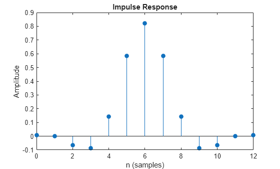
Plot the impulse response of the filter. The zeroth order coefficient is delayed by 7 samples, which is equal to the group delay of the filter.
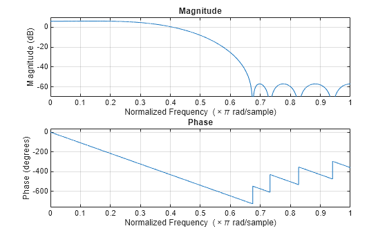
Plot the magnitude and phase responses of the filter.
Design a compensation interpolator for an existing CIC interpolator having six sections and an interpolation factor of 16.
CICInterp = dsp.CICInterpolator(InterpolationFactor=16,... NumSections=6)
CICInterp = dsp.CICInterpolator with properties:
InterpolationFactor: 16
  DifferentialDelay: 1
        NumSections: 6
 FixedPointDataType: 'Full precision'
Construct the compensation interpolator. Specify an interpolation factor of 2, an input sample rate of 600 Hz, a passband frequency of 100 Hz, and a stopband frequency of 250 Hz. Set the minimum attenuation of alias components in the stopband to be at least 80 dB.
fs = 600; fPass = 100; fStop = 250; ast = 80;
CICCompInterp = dsp.CICCompensationInterpolator(CICInterp,... InterpolationFactor=2,PassbandFrequency=fPass, ... StopbandFrequency=fStop,StopbandAttenuation=ast, ... SampleRate=fs)
CICCompInterp = dsp.CICCompensationInterpolator with properties:
  CICRateChangeFactor: 16
       CICNumSections: 6
 CICDifferentialDelay: 1
  InterpolationFactor: 2
  NormalizedFrequency: false
DesignForMinimumOrder: true
    PassbandFrequency: 100
    StopbandFrequency: 250
       PassbandRipple: 0.1000
  StopbandAttenuation: 80
           SampleRate: 600
Show all properties
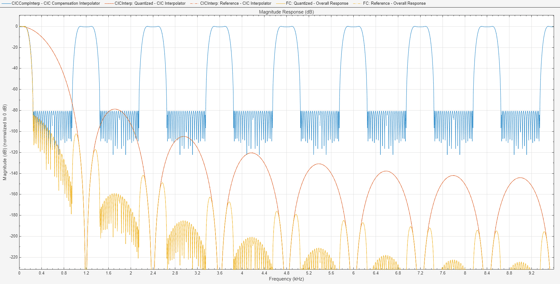
Visualize the frequency response of the cascade. Normalize all magnitude responses to 0 dB.
FC = dsp.FilterCascade(CICCompInterp, CICInterp);
f = filterAnalyzer(CICCompInterp,CICInterp,FC,... SampleRates=[fs2 fs162 fs16*2],NormalizeMagnitude=true); showFilters(f,false,FilterNames=["FC_Stage1","FC_Stage2"]); setLegendStrings(f,["CIC Compensation Interpolator","CIC Interpolator", ... "Overall Response"]);
Apply the design to a 1000-sample random input signal.
x = dsp.SignalSource(fi(rand(1000,1),1,16,15),SamplesPerFrame=100);
y = fi(zeros(32000,1),1,32,20); for ind = 1:10 x2 = CICCompInterp(x()); y(((ind-1)3200)+1:ind3200) = CICInterp(x2); end
More About
Algorithms
The response of a CIC filter is given by:
R, D, and N are the rate change factor, the differential delay, and the number of sections in the CIC filter, respectively.
After decimation, the CIC response has the form:
The normalized version of this last response is the one that the CIC compensator needs to compensate. Hence, the passband response of the CIC compensator should take the following form:
where _ω_p is the passband frequency of the CIC compensation filter.
Notice that when ω/2_R_ ≪ π, the previous equation for Hciccomp(ω) can be simplified using the fact that sin(x) ≅ x:
This previous equation is the inverse sinc approximation to the true inverse passband response of the CIC filter.
Extended Capabilities
Version History
Introduced in R2014b
Starting in R2025a, the Filter Design HDL Coder™ product is discontinued. So, this object no longer supports HDL code generation and the generatehdl function.
When you set the NormalizedFrequency property totrue, you must specify the passband frequency and stopband frequency in normalized frequency units (0 to 1). For more information, see the NormalizedFrequency property description.