dsp.DCBlocker - Block DC component (offset) from input signal - MATLAB (original) (raw)
Block DC component (offset) from input signal
Description
The dsp.DCBlocker System object™ removes the DC offset from each channel (column) of the input signal. The operation runs over time to continually estimate and remove the DC offset.
To block the DC component of the input signal:
- Create the
dsp.DCBlockerobject and set its properties. - Call the object with arguments, as if it were a function.
To learn more about how System objects work, see What Are System Objects?
The object supports C/C++ code generation and SIMD code generation under certain conditions. For more information, see Code Generation.
Creation
Syntax
Description
`dcblker` = dsp.DCBlocker creates a DC blocker System object, dcblker, to block the DC component from each channel (column) of the input signal.
`dcblker` = dsp.DCBlocker(`Name=Value`) sets properties using one or more name-value arguments. For example, to specify the normalized bandwidth of lowpass IIR or CIC filter as 0.004, set NormalizedBandwidth to 0.004.
Properties
Unless otherwise indicated, properties are nontunable, which means you cannot change their values after calling the object. Objects lock when you call them, and therelease function unlocks them.
If a property is tunable, you can change its value at any time.
For more information on changing property values, seeSystem Design in MATLAB Using System Objects.
Algorithm for estimating DC offset, specified as one of the following:
"IIR"–– The object uses a recursive estimate based on a narrow, lowpass elliptic filter. The Order property sets the order of the filter, and the NormalizedBandwidth property sets its bandwidth. This algorithm typically uses less memory than the FIR algorithm and is more efficient."FIR"–– The object uses a nonrecursive, moving average estimate based on a finite number of past input samples. The Length property sets the number of samples. The FIR filter has a linear phase response and does not cause any phase distortion to the signal. The IIR filter requires less memory and is more efficient to implement."CIC"–– The object uses a CIC decimator, with a decimation factor of 1, whose differential delay is calculated using theNormalizedBandwidthproperty. It uses two sections to ensure that the first sidelobe attenuation is at least 25 dB below the main lobe of the filter. This algorithm requires fixed-point inputs and can be used for HDL code generation."Subtract mean"–– The object computes the means of the columns of the input matrix, and subtracts the means from the input. This method does not retain state between inputs.
You can visualize the IIR, FIR, and CIC responses by using the fvtool function.
Normalized bandwidth of the IIR or CIC filter, specified as a real scalar greater than 0 or less than 1. The normalized bandwidth is used to estimate the DC component of the input signal.
Dependencies
This property applies only when you set the Algorithm property to"IIR" or "CIC".
Order of the lowpass IIR elliptic filter that is used to estimate the DC level, specified as an integer greater than 3.
Dependencies
This property applies only when you set the Algorithm property to"IIR".
Number of past input samples used in the FIR algorithm to estimate the running mean, specified as a positive integer.
Dependencies
This property applies only when you set the Algorithm property to"FIR".
Usage
Syntax
Description
[dcblkerOut](#d126e264764) = dcblker([input](#d126e264712)) removes the DC component from each channel (column) of the input and returns the output.
Input Arguments
Data input to the DC blocker object, specified as a vector, matrix, or_N_-D array.
Data Types: single | double | int8 | int16 | int32 | fi
Complex Number Support: Yes
Output Arguments
Signal with DC component removed, returned as a vector, matrix, or_N_-D array. The output dimensions match the input dimensions.
Data Types: single | double | int8 | int16 | int32 | fi
Complex Number Support: Yes
Object Functions
To use an object function, specify the System object as the first input argument. For example, to release system resources of a System object named obj, use this syntax:
| freqz | Frequency response of discrete-time filter System object |
|---|---|
| filterAnalyzer | Analyze filters with Filter Analyzer app |
| impz | Impulse response of discrete-time filter System object |
| info | Information about filter System object |
| coeffs | Returns the filter System object coefficients in a structure |
| cost | Estimate cost of implementing filter System object |
| grpdelay | Group delay response of discrete-time filter System object |
| outputDelay | Determine output delay of single-rate or multirate filter |
| step | Run System object algorithm |
|---|---|
| release | Release resources and allow changes to System object property values and input characteristics |
| reset | Reset internal states of System object |
Examples
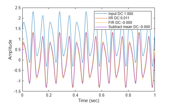
Remove the DC component of an input signal using the IIR, FIR, and subtract mean estimation algorithms.
Create a signal composed of a 15 Hz tone, a 25 Hz tone, and a DC offset.
t = (0:0.001:100)'; x = sin(30pit) + 0.33cos(50pi*t) + 1;
Create three DC blocker objects for the three estimation algorithms.
dc1 = dsp.DCBlocker(Algorithm="IIR",Order=6); dc2 = dsp.DCBlocker(Algorithm="FIR",Length=100); dc3 = dsp.DCBlocker(Algorithm="Subtract mean");
For each second of time, pass the input signal through the DC blockers. By implementing the DC blockers in 1-second increments, you can observe differences in the convergence times.
for idx = 1 : 100 range = (1:1000) + 1000*(idx-1); y1 = dc1(x(range)); % IIR estimate y2 = dc2(x(range)); % FIR estimate y3 = dc3(x(range)); % Subtract mean end
Plot the input and output data for the three DC blockers for the first second of time, and show the mean value for each signal. The mean values for the three algorithm types show that the FIR and Subtract mean algorithms converge more quickly.
plot(t(1:1000),x(1:1000), ... t(1:1000),y1, ... t(1:1000),y2, ... t(1:1000),y3); xlabel("Time (sec)") ylabel("Amplitude") legend(sprintf("Input DC:%.3f",mean(x)), ... sprintf("IIR DC:%.3f",mean(y1)), ... sprintf("FIR DC:%.3f",mean(y2)), ... sprintf("Subtract mean DC:%.3f",mean(y3)));
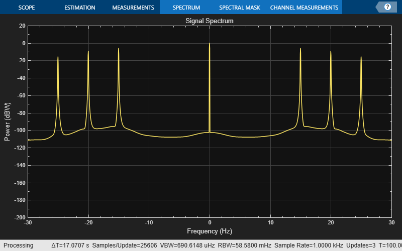
Compare the spectrum of an input signal with a DC offset to the spectrum of the same signal after applying a DC blocker. Enable the DC blocker to use the FIR estimation algorithm.
Create an input signal composed of three tones and that has a DC offset of 1. Set the sampling frequency to 1 kHz and set the signal duration to 100 seconds.
fs = 1000; t = (0:1/fs:100)'; x = sin(30pit) + 0.67sin(40pit) + 0.33sin(50pit) + 1;
Create a DC blocker object that uses the FIR algorithm to estimate the DC offset.
dcblker = dsp.DCBlocker(Algorithm="FIR",Length=100);
Create a spectrum analyzer with power units set to dBW and a frequency range of [-30 30] to display the frequency response of the input signal. Using the clone function, create a second spectrum analyzer to display the response of the output. Then, use the Title property of the spectrum analyzers to label them.
hsa = spectrumAnalyzer(SampleRate=fs, ... Method="welch",... AveragingMethod="exponential",... SpectrumUnits="dBW",FrequencySpan="start-and-stop-frequencies",... StartFrequency=-30,StopFrequency=30,YLimits=[-200 20],... Title="Signal Spectrum");
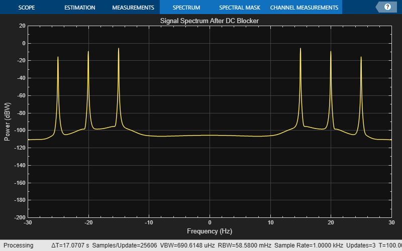
hsb = clone(hsa); hsb.Title = "Signal Spectrum After DC Blocker";
Pass the input signal, x, through the DC blocker to generate the output signal, y.
Use the first spectrum analyzer to display the frequency characteristics of the input signal. The tones at 15, 20, and 25 Hz, and the DC component, are clearly visible.
Use the second spectrum analyzer to display the frequency characteristics of the output signal. The DC component has been removed.
Algorithms
The DC blocker subtracts the DC component from the input signal. You can estimate the DC component by using the IIR, FIR, CIC, or subtract mean algorithm.
Pass the input signal through an IIR lowpass elliptical filter.
The elliptical IIR filter has a passband ripple of 0.1 dB and a stopband attenuation of 60 dB. You specify the normalized bandwidth and the filter order.
Pass the input signal through an FIR filter that uses a nonrecursive moving average from a finite number of past input samples.
The FIR filter coefficients are given as ones(1,Length)/Length, where Length is the number of past input samples for FIR algorithm. The FIR filter structure is a direct form I transposed structure.
Pass the input signal through a CIC filter. Because the CIC filter amplifies the signal, the filter gain is estimated and subtracted from the DC estimate.
The Cascaded Integrator-Comb (CIC) filter consists of two integrator-comb pairs. These pairs help to ensure that the peak of the first sidelobe of the filter response is attenuated by at least 25 dB relative to the peak of the main lobe. The normalized 3 dB bandwidth is used to calculate the differential delay. The delay is used to determine the gain of the CIC filter. The inverse of the filter gain is used as a multiplier, which is applied to the output of the CIC filter. This ensures that the aggregate gain of the DC estimate is 0 dB.
The following equation characterizes the aggregate magnitude response of the filter and the multiplier:
- Bnorm is the normalized bandwidth such that 0 < Bnorm < 1.
- M is the differential delay in samples.
- N is the number of sections, equal to 2.
Set the differential delay, M, to the smallest integer such that |H(ejω)| < 1/√2. Once M is known, the gain of the CIC filter is calculated as MN. Therefore, to precisely compensate for the filter gain, the multiplier is set to (1/M)N.
Compute the mean value of each column of the input signal and subtract the mean from the input. For example, if the input is [1 2 3 4; 3 4 5 6], then a DC Blocker set to this mode outputs [-1 -1 -1 -1; 1 1 1 1].
References
[1] Nezami, M. “Performance Assessment of Baseband Algorithms for Direct Conversion Tactical Software Defined Receivers: I/Q Imbalance Correction, Image Rejection, DC Removal, and Channelization.” MILCOM, 2002.
Extended Capabilities
For workflow and limitations, see HDL Code Generation for System Objects (HDL Coder).
Note
For a hardware-optimized dc blocker algorithm that supports HDL code generation, seeGenerate HDL Code for IIR Filter (DSP HDL Toolbox). The example models hardware-friendly valid and reset control signals, and exact hardware latency behavior, by using the dsphdl.BiquadFilter (DSP HDL Toolbox) System object. The DSP HDL Toolbox™ object supports HDL code generation with HDL Coder™ tools.
Version History
Introduced in R2014a
Starting in R2025a, the Filter Design HDL Coder™ product is discontinued. So, this object no longer supports HDL code generation by using the generatehdl function. The object still supports code generation using HDL Coder tools.