dsp.HighpassFilter - FIR or IIR highpass filter - MATLAB (original) (raw)
FIR or IIR highpass filter
Description
The dsp.HighpassFilter System object™ independently filters each channel of the input over time using the given design specifications. You can set the FilterType property ofdsp.HighpassFilter to 'FIR' or 'IIR' to implement the object as an FIR or IIR highpass filter.
When the FilterType property is set to 'FIR', using this object is an alternative to using the firceqrip andfirgr functions with dsp.FIRFilter. Thedsp.HighpassFilter object condenses the two-step process into one. You can use measure to verify that the design meets the prescribed specifications.
To filter each channel of your input:
- Create the
dsp.HighpassFilterobject and set its properties. - Call the object with arguments, as if it were a function.
To learn more about how System objects work, see What Are System Objects?
This object supports C/C++ code generation and SIMD code generation under certain conditions. This object also supports code generation for ARM® Cortex®-M and ARM Cortex-A processors. For more information, see Code Generation.
Creation
Syntax
Description
`HPF` = dsp.HighpassFilter returns a minimum order FIR highpass filter, HPF, with the default filter settings. Calling the object with the default property settings filters the input data with a stopband frequency of 8 kHz, a passband frequency of12 kHz, a stopband attenuation of 80 dB, and a passband ripple of 0.1 dB.
`HPF` = dsp.HighpassFilter(`Name=Value`) returns a highpass filter with additional properties specified by one or moreName-Value pair arguments. Name is the property name and Value is the corresponding value. For example,StopbandFrequency=8000 sets the stopband frequency specification of the filter to 8000 Hz.
Properties
Unless otherwise indicated, properties are nontunable, which means you cannot change their values after calling the object. Objects lock when you call them, and therelease function unlocks them.
If a property is tunable, you can change its value at any time.
For more information on changing property values, seeSystem Design in MATLAB Using System Objects.
Filter type, specified as one of these options:
'FIR'— The object designs an FIR highpass filter.'IIR'— The object designs an IIR highpass (biquad) filter.
Flag to design minimum order filter, specified as:
true–– The object designs the minimum order filter that meets the filter design specifications.false–– The object designs the filter with the order that you specify in theFilterOrderproperty.
Order of the FIR or IIR filter, specified as a positive integer.
Dependencies
To enable this property, set DesignForMinimumOrder tofalse.
Data Types: single | double | int8 | int16 | int32 | int64 | uint8 | uint16 | uint32 | uint64
Filter stopband edge frequency, specified as a real positive scalar in Hz or in normalized frequency units (since R2023a).
If you set theNormalizedFrequency property to:
false–– The value of the stopband edge frequency is in Hz. The value must be less than the passband edge frequency and half theSampleRateproperty value.true–– The value of the stopband edge frequency is in normalized frequency units. The value must be a positive scalar less than the passband edge frequency and less than1.0.
(since R2023a)
Dependencies
To enable this property, set the DesignForMinimumOrder property to true.
Data Types: single | double | int8 | int16 | int32 | int64 | uint8 | uint16 | uint32 | uint64
Filter passband edge frequency, specified as a real positive scalar in Hz or in normalized frequency units (since R2023a).
If you set theNormalizedFrequency property to:
false–– The value of the passband edge frequency is in Hz. The value must be less than half theSampleRateproperty value and greater than theStopbandFrequencyproperty value.true–– The value of the passband edge frequency is in normalized frequency units. The value must be a positive scalar less than1.0and greater than theStopbandFrequencyproperty value.
(since R2023a)
Data Types: single | double | int8 | int16 | int32 | int64 | uint8 | uint16 | uint32 | uint64
Minimum attenuation in the stopband, specified as a real positive scalar in dB.
Data Types: single | double | int8 | int16 | int32 | int64 | uint8 | uint16 | uint32 | uint64
Maximum ripple of filter response in the passband, specified as a real positive scalar in dB.
Data Types: single | double | int8 | int16 | int32 | int64 | uint8 | uint16 | uint32 | uint64
Since R2023a
Flag to set frequencies in normalized units, specified as one of these values:
true–– The passband edge and stopband edge frequencies must be in the normalized frequency units and less than1.0.false–– The passband edge and stopband edge frequencies are in Hz. You can specify the input sample rate through theSampleRateproperty.
Data Types: logical
Input sample rate in Hz, specified as a positive real scalar.
Dependency
To enable this property, setNormalizedFrequency to false. (since R2023a)
Data Types: single | double
Fixed-Point Properties
Rounding method for output fixed-point operations, specified as a character vector. For more information on the rounding modes, see Precision and Range.
Word and fraction lengths of coefficients, specified as anumerictype object. The default,numerictype(1,16) corresponds to a signed numeric type object with 16-bit coefficients and a fraction length determined based on the coefficient values, to give the best possible precision.
This property is not tunable.
Word length of the output is same as the word length of the input. Fraction length of the output is computed such that the entire dynamic range of the output can be represented without overflow. For details on how the fraction length of the output is computed, see Fixed-Point Precision Rules for Avoiding Overflow in FIR Filters.
Usage
Syntax
Description
[y](#d126e302968) = HPF([x](#d126e302913)) highpass filters the input signal, x. y is a highpass-filtered version of x.
Input Arguments
Noisy data input, specified as a vector or a matrix. If the input signal is a matrix, each column of the matrix is treated as an independent channel. The number of rows in the input signal denote the channel length. This object accepts variable-size inputs. After the object is locked, you can change the size of each input channel, but you cannot change the number of channels.
Data Types: single | double | int8 | int16 | int32 | int64 | uint8 | uint16 | uint32 | uint64 | fi
Complex Number Support: Yes
Output Arguments
Filtered output, returned as a vector or a matrix. The output has the same size, data type, and complexity characteristics as the input.
Data Types: single | double | int8 | int16 | int32 | int64 | uint8 | uint16 | uint32 | uint64 | fi
Complex Number Support: Yes
Object Functions
To use an object function, specify the System object as the first input argument. For example, to release system resources of a System object named obj, use this syntax:
| freqz | Frequency response of discrete-time filter System object |
|---|---|
| filterAnalyzer | Analyze filters with Filter Analyzer app |
| impz | Impulse response of discrete-time filter System object |
| info | Information about filter System object |
| coeffs | Returns the filter System object coefficients in a structure |
| cost | Estimate cost of implementing filter System object |
| grpdelay | Group delay response of discrete-time filter System object |
| outputDelay | Determine output delay of single-rate or multirate filter |
| measure | Measure frequency response characteristics of filter System object |
| step | Run System object algorithm |
|---|---|
| release | Release resources and allow changes to System object property values and input characteristics |
| reset | Reset internal states of System object |
Examples
Create a minimum order FIR highpass filter for data sampled at 44.1 kHz. Specify a passband frequency of 12 kHz, a stopband frequency of 8 kHz, a passband ripple of 0.1 dB, and a stopband attenuation of 80 dB.
Fs = 44.1e3; filtertype = 'FIR'; Fpass = 12e3; Fstop = 8e3; Rp = 0.1; Astop = 80; FIRHPF = dsp.HighpassFilter(SampleRate=Fs,... FilterType=filtertype,... PassbandFrequency=Fpass,... StopbandFrequency=Fstop,... PassbandRipple=Rp,... StopbandAttenuation=Astop);
Design a minimum order IIR highpass filter with the same properties as the FIR highpass filter. Use clone to create a system object with the same properties as the FIR Highpass filter. Change the FilterType property of the cloned filter to IIR.
IIRHPF = clone(FIRHPF); IIRHPF.FilterType = 'IIR';
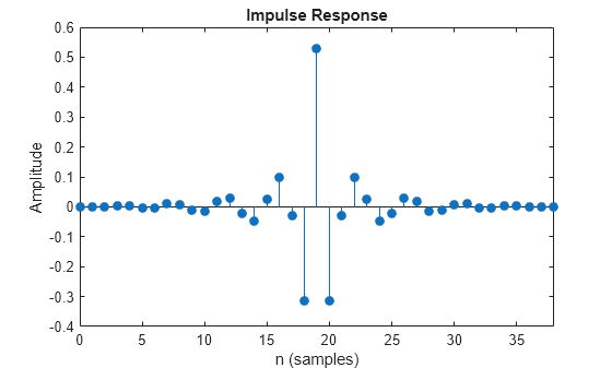
Plot the impulse response of the FIR highpass filter. The zeroth order coefficient is delayed by 19 samples, which is equal to the group delay of the filter. The FIR highpass filter is a causal FIR filter
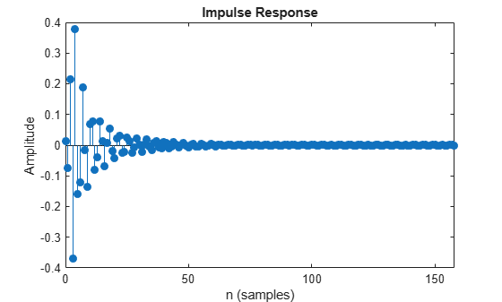
Plot the impulse response of the IIR highpass filter.
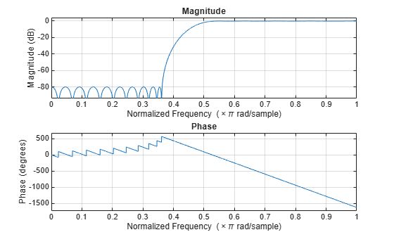
Plot the magnitude and phase response of the FIR highpass filter.
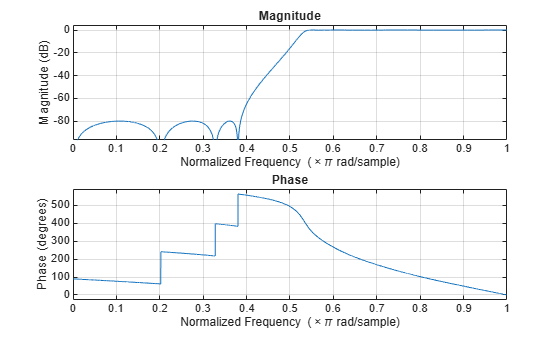
Plot the magnitude and phase response of the IIR highpass filter.
Calculate the cost of implementing the FIR highpass filter.
ans = struct with fields: NumCoefficients: 39 NumStates: 38 MultiplicationsPerInputSample: 39 AdditionsPerInputSample: 38
Calculate the cost of implementing the IIR highpass filter. The IIR filter is more efficient to implement than its FIR counterpart.
ans = struct with fields: NumCoefficients: 18 NumStates: 14 MultiplicationsPerInputSample: 18 AdditionsPerInputSample: 14
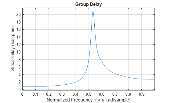
Calculate the group delay of the FIR highpass filter.
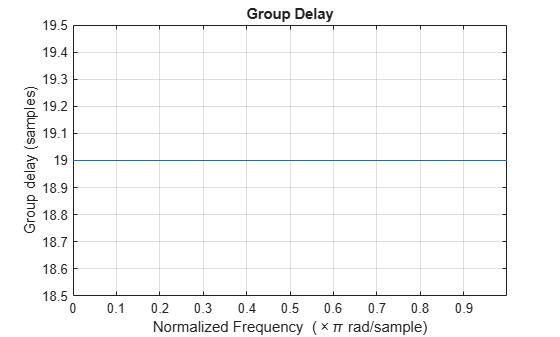
Calculate the group delay of the IIR highpass filter. The FIR filter has a constant group delay (linear phase) while its IIR counterpart does not.
Create a highpass filter using the dsp.HighpassFilter object. Setting the NormalizedFrequency property to true designs the filter with frequency specifications in normalized frequency units.
LPF = dsp.HighpassFilter(NormalizedFrequency=true)
LPF = dsp.HighpassFilter with properties:
           FilterType: 'FIR'
DesignForMinimumOrder: true
    StopbandFrequency: 0.3628
    PassbandFrequency: 0.5442
  StopbandAttenuation: 80
       PassbandRipple: 0.1000
  NormalizedFrequency: true
Show all properties
Create a spectrumAnalyzer object to visualize the input and output signal spectra. With a sample rate of 44.1e3 Hz, the stopband frequency and the passband frequency of the filter translate to 8000 Hz and 12000 Hz, respectively.
SA = spectrumAnalyzer(SampleRate=44.1e3,... PlotAsTwoSidedSpectrum=false,ShowLegend=true,... YLimits=[-150 30],... Title='Input Signal and Output Signal of Lowpass Filter'); SA.ChannelNames = {'Input','Output'};
Run the highpass filter algorithm to filter the white Gaussian noisy input signal. View the input and output signals using the spectrum analyzer.
for k = 1:100 Input = randn(1024,1);
Output = LPF(Input);

SA([Input,Output]);
end

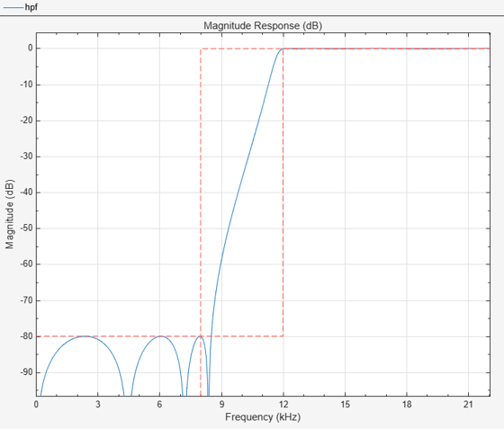
Set up the IIR highpass filter. The sampling rate of the white Gaussian noise is 44,100 Hz. The passband frequency of the filter is 12 kHz, the stopband frequency is 8 kHz, the passband ripple is 0.1 dB, and the stopband attenuation is 80 dB.
Fs = 44.1e3; filtertype = 'IIR'; Fpass = 12e3; Fstop = 8e3; Rp = 0.1; Astop = 80; hpf = dsp.HighpassFilter(SampleRate=Fs,... FilterType=filtertype,... PassbandFrequency=Fpass,... StopbandFrequency=Fstop,... PassbandRipple=Rp,... StopbandAttenuation=Astop);
View the magnitude response of the highpass filter.
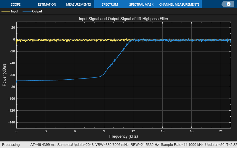
Create a spectrum analyzer object.
sa = spectrumAnalyzer(SampleRate=44.1e3,... PlotAsTwoSidedSpectrum=false,ShowLegend=true,... YLimits=[-150 30],... Title='Input Signal and Output Signal of IIR Highpass Filter'); sa.ChannelNames = {'Input','Output'};
Filter the white Gaussian noisy input signal. View the input and output signals using the spectrum analyzer.
for k = 1:100 Input = randn(1024,1); Output = hpf(Input); sa([Input,Output]); end
Measure the frequency response characteristics of a highpass filter. Create a dsp.HighpassFilter System object with default properties. Measure the frequency response characteristics of the filter.
HPF = dsp.HighpassFilter with properties:
           FilterType: 'FIR'
DesignForMinimumOrder: true
    StopbandFrequency: 8000
    PassbandFrequency: 12000
  StopbandAttenuation: 80
       PassbandRipple: 0.1000
  NormalizedFrequency: false
           SampleRate: 44100
Show all properties
HPFMeas =
Sample Rate : 44.1 kHz
Stopband Edge : 8 kHz
6-dB Point : 10.418 kHz
3-dB Point : 10.8594 kHz
Passband Edge : 12 kHz
Stopband Atten. : 81.8558 dB
Passband Ripple : 0.08066 dB
Transition Width : 4 kHz
More About
For a hardware-optimized filter algorithm that supports HDL code generation, use adsphdl.FIRFilter (DSP HDL Toolbox) or a dsphdl.BiquadFilter (DSP HDL Toolbox) System object. These objects have hardware-friendly valid and reset control signals, and model exact hardware latency behavior. The objects support HDL code generation with HDL Coder™ tools.
Algorithms
For the minimum order design, the algorithm uses generalized Remez FIR filter design algorithm. For the specified order design, the algorithm uses the constrained equiripple FIR filter design algorithm. The designed filter is then implemented as a linear phase Type-1 filter with a Direct form structure.
In the IIR configuration, the algorithm uses the elliptic design method to compute the SOS and scale values required to meet the filter design specifications. The algorithm uses the SOS and scale values to setup a Direct form I biquadratic IIR filter, which forms the basis of the IIR version of the highpass filter.
References
[1] Shpak, D.J., and A. Antoniou. "A generalized Remez method for the design of FIR digital filters." IEEE® Transactions on Circuits and Systems. Vol. 37, Issue 2, Feb. 1990, pp. 161–174.
[2] Selesnick, I.W., and C. S. Burrus. "Exchange algorithms that complement the Parks-McClellan algorithm for linear-phase FIR filter design." IEEE Transactions on Circuits and Systems. Vol. 44, Issue 2, Feb. 1997, pp. 137–143.
Extended Capabilities
Version History
Introduced in R2015a
Starting in R2025a, the Filter Design HDL Coder™ product is discontinued. So, this object no longer supports HDL code generation by using the generatehdl function. For a hardware-optimized FIR filter algorithm that supports HDL code generation, use a dsphdl.FIRFilter (DSP HDL Toolbox) or a dsphdl.BiquadFilter (DSP HDL Toolbox) System object.
When you set the NormalizedFrequency property totrue, you must specify the passband and stopband frequencies in normalized frequency units (0 to 1).
When you set the NormalizedFrequency property totrue while creating the object, the passband and stopband frequency values are automatically set to normalized frequency units using the default sample rate of 44100 Hz.
hpFilter = dsp.HighpassFilter(NormalizedFrequency=true)
hpFilter = dsp.HighpassFilter with properties:
           FilterType: 'FIR'
DesignForMinimumOrder: true
    StopbandFrequency: 0.3628
    PassbandFrequency: 0.5442
  StopbandAttenuation: 80
       PassbandRipple: 0.1000
  NormalizedFrequency: true
When you set the NormalizedFrequency property totrue after you create the object, the passband and stopband frequencies must be manually set to the normalized frequency values before you run the object algorithm.
hpFilter = dsp.HighpassFilter
hpFilter = dsp.HighpassFilter with properties:
           FilterType: 'FIR'
DesignForMinimumOrder: true
    StopbandFrequency: 8000
    PassbandFrequency: 12000
  StopbandAttenuation: 80
       PassbandRipple: 0.1000
  NormalizedFrequency: false
           SampleRate: 44100
To specify the normalized frequency values, set NormalizedFrequency totrue and manually convert the frequency values in Hz to normalized values using the input sample rate in Hz. For example, if the input sample rate is 44100 Hz, the corresponding values in normalized units are computed using these equations.
hpFilter.NormalizedFrequency = true; hpFilter.StopbandFrequency = 8000/(44100/2); hpFilter.PassbandFrequency = 12000/(44100/2)
hpFilter = dsp.HighpassFilter with properties:
           FilterType: 'FIR'
DesignForMinimumOrder: true
    StopbandFrequency: 0.3628
    PassbandFrequency: 0.5442
  StopbandAttenuation: 80
       PassbandRipple: 0.1000
  NormalizedFrequency: true