dsp.VariableBandwidthFIRFilter - Variable bandwidth FIR filter - MATLAB (original) (raw)
Variable bandwidth FIR filter
Description
The dsp.VariableBandwidthFIRFilter object filters each channel of the input using FIR filter implementations. It does so while having the capability of tuning the bandwidth.
To filter each channel of the input:
- Create the
dsp.VariableBandwidthFIRFilterobject and set its properties. - Call the object with arguments, as if it were a function.
To learn more about how System objects work, see What Are System Objects?
This object supports C/C++ code generation and SIMD code generation under certain conditions. For more information, see Code Generation.
Creation
Syntax
Description
`vbw` = dsp.VariableBandwidthFIRFilter returns a variable bandwidth FIR filter object which independently filters each channel of the input over successive calls to the object. The filter cutoff frequency can be tuned during the filtering operation. The variable bandwidth FIR filter is designed using the window method.
`vbw` = dsp.VariableBandwidthFIRFilter(`Name=Value`) returns a variable bandwidth FIR filter with additional properties specified by one or more Name-Value pair arguments. Name is the property name and Value is the corresponding value. For example,FilterOrder=50 sets the filter order to 50.
Properties
Unless otherwise indicated, properties are nontunable, which means you cannot change their values after calling the object. Objects lock when you call them, and therelease function unlocks them.
If a property is tunable, you can change its value at any time.
For more information on changing property values, seeSystem Design in MATLAB Using System Objects.
FilterOrder — FIR filter order
30 (default) | even positive integer
FIR filter order, specified as an even positive integer. This property is nontunable.
Data Types: double | single
FilterType — Type of filter response
'Lowpass' (default) | 'Highpass' | 'Bandpass' | 'Bandstop'
Type of filter response, specified as one of these options:
'Lowpass''Highpass''Bandpass''Bandstop'
CutoffFrequency — Filter cutoff frequency
512 (default) | positive scalar
Filter cutoff frequency, specified as a real positive scalar in Hz or in normalized frequency units (since R2023a).
If you set theNormalizedFrequency property to:
false–– The value of the cutoff frequency is in Hz. The value must be less than half theSampleRateproperty value.true–– The value of the cutoff frequency is in normalized frequency units. The value must be a positive scalar less than1.0.
(since R2023a)
Tunable: Yes
Dependencies
To enable this property, set FilterType to'Lowpass' or 'Highpass'.
Data Types: double | single
Window — Window function
'Hann' (default) | 'Hamming' | 'Chebyshev' | 'Kaiser'
Window function used to design the FIR filter, specified as one of these options:
'Hann''Hamming''Chebyshev''Kaiser'
KaiserWindowParameter — Kaiser window parameter
0.5 (default) | real scalar
Kaiser window parameter, specified as a real scalar.
Dependencies
To enable this property, set the Window property to'Kaiser'.
Data Types: double | single
CenterFrequency — Center frequency of filter
11025 (default) | positive scalar
Center frequency of filter, specified as a real positive scalar in Hz or in normalized frequency units (since R2023a).
If you set theNormalizedFrequency property to:
false–– The value of the center frequency is in Hz. The value must be less than half theSampleRateproperty value.true–– The value of the center frequency is in normalized frequency units. The value must be a positive scalar less than1.0.
(since R2023a)
Tunable: Yes
Dependencies
To enable this property, set the FilterType property to'Bandpass' or 'Bandstop'.
Data Types: double | single
Bandwidth — Filter bandwidth
7680 (default) | positive scalar
Filter bandwidth, specified as a real positive scalar in Hz or in normalized frequency units (since R2023a).
If you set theNormalizedFrequency property to:
false–– The value of the filter bandwidth is in Hz. The value must be less than half theSampleRateproperty value.true–– The value of the filter bandwidth is in normalized frequency units. The value must be a positive scalar less than1.0.
(since R2023a)
Tunable: Yes
Dependencies
To enable this property, set the FilterType property to'Bandpass' or 'Bandstop'.
Data Types: double | single
SidelobeAttenuation — Chebyshev window sidelobe attenuation
60 (default) | positive scalar
Chebyshev window sidelobe attenuation, specified as a real positive scalar in dB.
Dependencies
To enable this property, set the Window property to'Chebyshev'.
Data Types: double | single
NormalizedFrequency — Flag to set frequencies in normalized units
false (default) | true
Since R2023a
Flag to set frequencies in normalized units, specified as one of these values:
true–– The filter cutoff frequency, center frequency, and the filter bandwidth must be in the normalized frequency units and less than1.0.false–– The filter cutoff frequency, center frequency, and the filter bandwidth are in Hz. You can specify the input sample rate through theSampleRateproperty.
Data Types: logical
SampleRate — Input sample rate
44100 (default) | positive scalar
Input sample rate, specified as a positive scalar in Hz.
Dependency
To enable this property, setNormalizedFrequency to false. (since R2023a)
Data Types: double | single
Usage
Syntax
Description
[y](#d126e388964) = vbw([x](#d126e388928)) filters the input signal x using the variable bandwidth FIR filter to produce the output y. The variable bandwidth FIR filter object operates on each channel, which means the object filters every column of the input signal independently over successive calls to the algorithm.
Input Arguments
x — Data input
vector | matrix
Data input, specified as a vector or a matrix. This object also accepts variable-size inputs. Once the object is locked, you can change the size of each input channel, but you cannot change the number of channels.
Data Types: double | single
Complex Number Support: Yes
Output Arguments
y — Filtered output
vector | matrix
Filtered output, returned as a vector or a matrix. The size, data type, and complexity of the output signal matches that of the input signal.
Data Types: double | single
Complex Number Support: Yes
Object Functions
To use an object function, specify the System object™ as the first input argument. For example, to release system resources of a System object named obj, use this syntax:
Specific to dsp.VariableBandwidthFIRFilter
| freqz | Frequency response of discrete-time filter System object |
|---|---|
| filterAnalyzer | Analyze filters with Filter Analyzer app |
| impz | Impulse response of discrete-time filter System object |
| info | Information about filter System object |
| coeffs | Returns the filter System object coefficients in a structure |
| cost | Estimate cost of implementing filter System object |
| grpdelay | Group delay response of discrete-time filter System object |
| outputDelay | Determine output delay of single-rate or multirate filter |
Common to All System Objects
| step | Run System object algorithm |
|---|---|
| release | Release resources and allow changes to System object property values and input characteristics |
| reset | Reset internal states of System object |
Examples
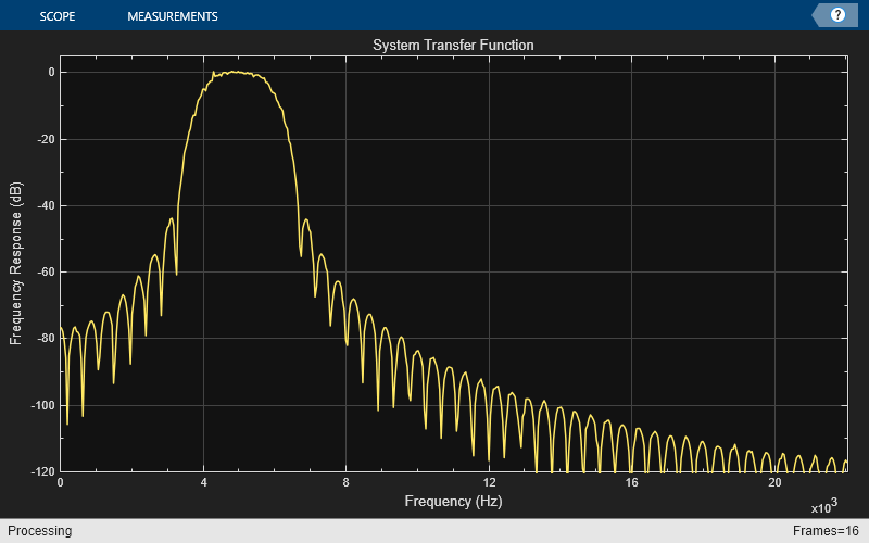
Filtering Through a Variable Bandwidth Bandpass FIR Filter
Tune the center frequency and the bandwidth of the FIR bandpass filter. Filter a sinusoidal signal through this filter.
Define a bandpass variable bandwidth FIR filter. Specify an input sample rate of 44100 Hz. Initialize a dsp.TransferFunctionEstimator object to estimate the transfer function of the filter from the input and output signals. To visualize the transfer function, initialize a dsp.ArrayPlot object.
Fs = 44100; vbw = dsp.VariableBandwidthFIRFilter(FilterType='Bandpass',... FilterOrder=100,... SampleRate=Fs,... CenterFrequency=1e4,... Bandwidth=4e3); tfe = dsp.TransferFunctionEstimator(FrequencyRange='onesided'); aplot = dsp.ArrayPlot(PlotType='Line',... XOffset=0,... YLimits=[-120 5], ... SampleIncrement=44100/1024,... YLabel='Frequency Response (dB)',... XLabel='Frequency (Hz)',... Title='System Transfer Function');
Generate a sine wave signal with a frame length of 1024. Tune the bandwidth and the center frequency of the filter. Pass the signal through this filter. Estimate the transfer function of the filter using the input and the generated output. Plot the system transfer function using an array plot.
FrameLength = 1024; sine = dsp.SineWave(SamplesPerFrame=FrameLength); for i=1:500 % Generate input x = sine() + randn(FrameLength,1); % Pass input through the filter y = vbw(x); % Transfer function estimation h = tfe(x,y); % Plot transfer function aplot(20*log10(abs(h))) % Tune bandwidth and center frequency of the FIR filter if (i==250) vbw.CenterFrequency = 5000; vbw.Bandwidth = 2000; end end
Algorithms
FIR Transformations
All transformations assume a lowpass filter of length 2N+1.
Lowpass to Lowpass
Consider an ideal lowpass brickwall filter with normalized cutoff frequency ωc1. By taking the inverse discrete Fourier transform of the ideal frequency response, and clipping the resulting sequence to length 2N+1, the impulse response is:
where w(n) is the window vector. Tune the lowpass filter coefficients to a new cutoff frequency ωc2 as follows:
You do not need to recompute the window every time you tune the cutoff frequency.
Lowpass to Highpass
Assuming a lowpass filter with normalized 6-dB cutoff frequency ωc, you can obtain a highpass filter with the same cutoff frequency by taking the complementary of the lowpass frequency response: HHP(ejω) = 1 − HLP(ejω)
Taking the inverse discrete Fourier transform of the above response, you have the following highpass filter coefficients:
Lowpass to Bandpass
Obtain a bandpass filter centered at frequency ω0 by shifting the lowpass response:
HBP(ejω) = HLP(ej(ω–ω0)) + HLP(ej(ω–ω0))
The bandwidth of the resulting bandpass filter is 2ωc, as measured between the two cutoff frequencies of the bandpass filter. The equivalent bandpass filter coefficients are then:
Lowpass to Bandstop
You can transform a lowpass filter to a bandstop filter by combining the highpass and bandpass transformations. First make the filter bandpass by shifting the lowpass response, and then invert it to get a bandstop response centered at ω0.
HBS(ejω) = 1 – (HLP(ej(ω–ω0)) + HLP(ej(ω+ω0)))
This yields the following coefficients:
Generalized Transformation
You can combine these transformations to transform a lowpass filter to a lowpass, highpass, bandpass, or bandstop filter with arbitrary cutoffs.
For example, to transform a lowpass filter with cutoff ωc1 to a highpass with cutoff ωc2, you first apply the lowpass-to-lowpass transformation to get a lowpass filter with cutoff ωc2, and then apply the lowpass-to-highpass transformation to get the highpass with cutoff ωc2.
To get a bandpass filter with center frequency ω0 and bandwidth β, we first apply the lowpass-to-lowpass transformation to go from a lowpass with cutoff ωc to a lowpass with cutoff β/2, and then apply the lowpass-to-bandpass transformation to get the desired bandpass filter. You can use the same approach for a bandstop filter.
References
[1] Jarske, P.,Y. Neuvo, and S. K. Mitra, "A simple approach to the design of linear phase FIR digital filters with variable characteristics." Signal Processing. Vol. 14, Issue 4, June 1988, pp. 313-326.
Extended Capabilities
Version History
Introduced in R2014a
R2023a: Support for normalized frequencies
When you set the NormalizedFrequency property totrue, you can specify the filter cutoff frequency, center frequency, and the filter bandwidth in normalized frequency units (0 to 1).
When you set the NormalizedFrequency property totrue while creating the object, the frequency values are automatically set to normalized frequency units using the default sample rate of 44100 Hz.
vbFIRFilter = dsp.VariableBandwidthFIRFilter(NormalizedFrequency=true)
vbFIRFilter = dsp.VariableBandwidthFIRFilter with properties:
        FilterOrder: 30
         FilterType: 'Lowpass'
    CutoffFrequency: 0.0232
             Window: 'Hann'
NormalizedFrequency: true
When you set the NormalizedFrequency property totrue after you create the object, the frequencies must be manually set to the normalized frequency values before you run the object algorithm.
vbFIRFilter = dsp.VariableBandwidthFIRFilter
vbFIRFilter = dsp.VariableBandwidthFIRFilter with properties:
        FilterOrder: 30
         FilterType: 'Lowpass'
    CutoffFrequency: 512
             Window: 'Hann'
NormalizedFrequency: false
         SampleRate: 44100
To specify the normalized frequency values, set NormalizedFrequency totrue and manually convert the frequency values in Hz to normalized values using the input sample rate in Hz. For example, if the input sample rate is 44100 Hz, the corresponding values in normalized units are computed using these equations.
vbFIRFilter.NormalizedFrequency = true; vbFIRFilter.CutoffFrequency = 512/(44100/2)
vbFIRFilter = dsp.VariableBandwidthFIRFilter with properties:
        FilterOrder: 30
         FilterType: 'Lowpass'
    CutoffFrequency: 0.0232
             Window: 'Hann'
NormalizedFrequency: true