Configure Signal Data for C Code Generation - MATLAB & Simulink (original) (raw)
Signal data consists of variables that store intermediate results in global memory as generated algorithmic code computes values of block output signals from block input signals, excluding signals that connect to root Inport and Outport blocks. Signal data is not signal lines in a model diagram. For example, in these cases, a signal line has no data representation in generated code:
- Feeds a function-call port
- Exits a message block, such as the Send block
- Crosses subsystem boundaries with no computation blocks in between
When you configure a model for code generation, you choose the block input and output signals to make accessible in the generated code. For example, configure signal data to:
- Make the data accessible for interaction and monitoring while the generated code executes.
- Minimize the amount of data that is stored in memory.
- Control where the code generator places signal data in memory.
- Promote signal data to the model interface so that other components and systems can access that data.
- Improve readability and traceability of the generated code.
The code generator checks for signal line configuration consistency. For example, the code generator verifies that the configuration of a signal line feeding into a subsystem matches the configuration of the signal line that exits the corresponding subsystem inport.
For code generation, examples show how to configure block signals for the model ConfigurationInterface. You can configure code mappings by using the Code Mappings Editor – C or code mappings programming interface (coder.mapping.api.CodeMapping).
Choose Code Configuration Options for Signals
Based on your code generation requirements, decide which block signals to represent in the generated code and how to represent the signal data. By default, signals in a model appear in generated code as fields of a global data structure named_`model`__B. If you do not configure customizations, the code generator determines whether to eliminate or change the representation of signals in generated code for optimization purposes. If you configure customizations, decide:
- Which signals to make accessible in the generated code
You must add signals that you want to make accessible in the generated code to the model code mappings. - Whether to set up a default configuration
If you need to gain access to a significant number (for example, more than 10) of signals , it is more efficient to configure the signals with default settings and then override those settings for special cases. If you need to gain access to a few signals that have unique source, naming, or placement requirements, consider configuring the signals individually. - How to declare and handle signal data in the generated code
- As separate global variables
- To read input data from global variables defined in external code
- As calls to access functions. Requires Embedded Coder®
For more information about these options, see Control Data and Function Interface in Generated Code.
Other considerations include whether to:
- Name signals in the generated code by using signal labels that appear in the model or by using unique code identifiers.
- Include the
volatiletype qualifier in global variable definitions and declarations. Requires Embedded Coder. See Protect Global Data with const and volatile Type Qualifiers. - Place signal data into a specific area of memory. Requires Embedded Coder. See Control Data and Function Placement in Memory by Inserting Pragmas.
For a list of interface requirements that are relevant to signals with corresponding storage classes and storage class properties, see Choose Storage Class and Storage Class Properties for Data Stores.
Signal requirements for example model ConfigurationInterface are:
- Configure signals that feed into and exit from the Switch block for code generation. Retain that signal data for monitoring while the generated code executes.
- Represent signals as separate global variables.
- Apply prefix
dout_to names of variables that represent signals.
Set the default representation of signals in the generated code as global variables that have the static type qualifier. Then, you configure the output signals of the two lookup table blocks to use the default storage class and unique code identifiers that include the required prefix dout_.
Add Signals to Model Code Mappings
Before you can configure a signal for code generation, add the signal to the model code mappings. Add the output signals for the two lookup table blocks to the model code mappings.
- Open example model
ConfigurationInterface. Save a copy of the model to a writable location.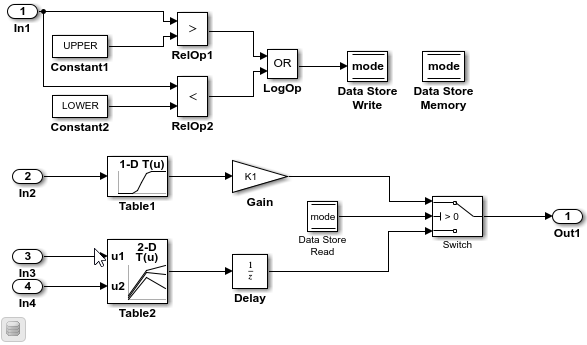
- Open the Embedded Coder app.
- In the C Code tab, select > .
- In the Code Mappings editor, click the Signals/States tab. No signals are listed.
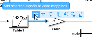
- Add signals to the code mappings. For the output signal of lookup table blocks
Table1andTable2:- In the model, select the signal.
- Pause on the ellipsis that appears above or below the signal line to open the action bar. Click the Add Signal button.
In the Code Mappings editor, the Signals node expands and lists the two signals that you added.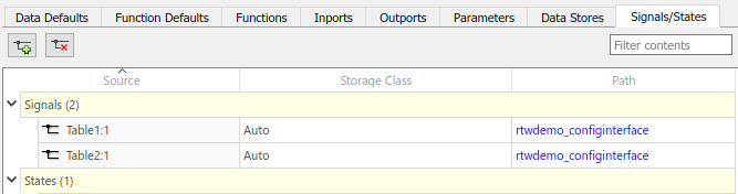
Configure Default Code Generation Settings for Signals
A default code generation setting for signals can reduce the effort of preparing a model for code generation, especially if a model has a significant number of signals that you want to monitor while the generated code executes. Choose configuration settings once, and the code generator applies those settings to signals across the model. Simulink® stores the default configuration as part of the model.
Consider configuring default code generation settings for model signals if your model uses multiple signals that do not have unique requirements or uses a shared Embedded Coder Dictionary.
This example shows how to use the Code Mappings Editor – C to set the default storage class for signals in the model ConfigurationInterface to FileScope. With that storage class setting, the code generator represents signal data in the generated code as global variables that have thestatic type qualifier.
- If you have not already done so, add signals to the model code mappings as described in Add Signals to Model Code Mappings.
- In the C Code tab, select > .
- In the Code Mappings editor, on the Data Defaults tab, under Signals, select category Signals, states, and internal data. Set the default storage class to
FileScope.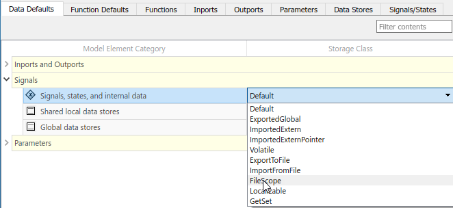
- Save the model.
Configure Code Generation Settings for Individual Signals
You can configure individual signals for code generation. For example, if a model has two signals that have unique code generation requirements, configure the signals individually. Or, if you configure default settings for signals, you can override those settings for specific signals.
If your model meets at least one of these criteria, consider configuring code generation settings for signals individually:
- Uses multiple signals that have unique source, naming, or placement requirements.
- Uses a few signals.
- Has a default configuration for signals and you need to override the configuration for some specific signals.
This example shows how to use the Code Mappings editor to apply your default storage class setting to the output signals of lookup table blocks Table1 andTable2 in model ConfigurationInterface. The example also shows how configure code identifiers for those output signals. You can specify code generation identifiers, for example for integration, without modifying the model design.
- If you have not already done so, complete the steps in Configure Default Code Generation Settings for Signals.
- In the Code Mappings editor, click the Signals/States tab. Expand Signals. The editor lists the names or block port identifiers of signals that you added to the code mappings. If a signal resolves to a signal object, a resolve-to-signal-object icon appears to the right of the element name or port identifier. The storage class for each signal is set to
Auto, which means that the code generator might eliminate or change the representation of relevant code for optimization purposes. If optimizations are not possible, the code generator applies the model default configuration. For this example, the model default configuration specifies storage classFileScope.- To avoid optimizations and force the code generator to use the default configuration, set the storage class to
Model default. - To override the default configuration, specify the storage class that meets the code generation requirements for that signal.
- To avoid optimizations and force the code generator to use the default configuration, set the storage class to
- In the Code Mappings editor, select the output signals for blocks
Table1andTable2. Set the storage class toModel default: FileScope. - Configure the code identifier for the output signals for the two lookup table blocks with names that include the prefix
dout_. In the Code Mappings editor, select signalTable1:1. Click the icon and set theIdentifier property to
 dout_Table1. For signalTable2:1, set Identifier todout_Table2.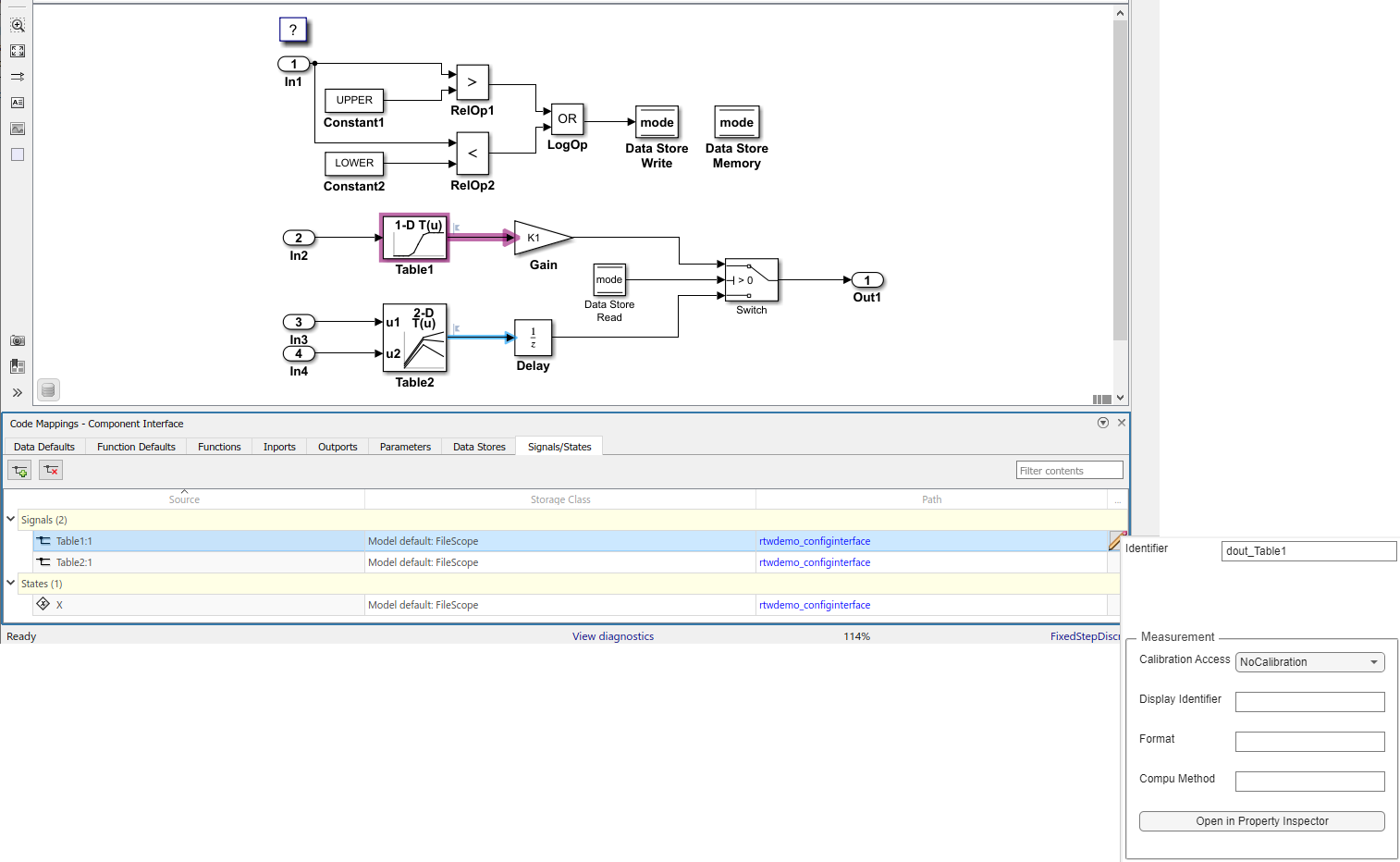
- Save the model.
- Generate and view the code. For example, in
ConfigurationInterface.c, find the data definitions for the lookup table data.
static MYTYPE dout_Table1;
static MYTYPE dout_Table2;
Find where lookup table data is used in the step entry-point function.
.
.
.
dout_Table1 = look1_binlc(input2, ((const MYTYPE *)&(mp_Table1.BP[0])), ((
const MYTYPE *)&(mp_Table1.Table[0])), 10U);
if (mode) {
output = (real_T)mp_K1 * dout_Table1;
} else {
output = dstate_X;
}
dout_Table2 = look2_binlc(input3, input4, ((const MYTYPE *)&(mp_Table2.BP1[0])),
((const MYTYPE *)&(mp_Table2.BP2[0])), ((const MYTYPE *)&(mp_Table2.Table[0])),
((const uint32_T *)&(rtwdemo_configi_Table2_maxIndex[0])), 3U);
dstate_X = dout_Table2;
}
Remove Signals from Model Code Mappings
- In the C Code tab, select > .
- In the Code Mappings editor, click the Signals/States tab.
- For each signal that you want to remove:
- In the model, select the signal.
- Pause on the ellipsis that appears above or below the signal line to open the action bar. Click the Remove Signal button.
Configure Code Generation Settings for Signals Programmatically
To automate configuration of signals for code generation, use the programming interface for code mappings. For example, when creating custom block libraries or part of an application test environment, use the programming interface to automate data configuration.
This example shows how to use the programming interface to configure signals for modelConfigurationInterface. Set the default representation of signals in the generated code as global variables that have the static type qualifier. Then, configure the output signals of the two lookup table blocks to use the default storage class and unique code identifiers that include the required prefix dout_.
- Open the example model.
openExample("ConfigurationInterface") - Create object
cmby calling functioncoder.mapping.api.get. The object stores the code generation configuration for data and functions for modelConfigurationInterface.
cm = coder.mapping.api.get("ConfigurationInterface"); - Configure default settings for signals by calling function
setDataDefault. For the arguments, specify these values:- The object returned by
coder.mapping.api.get InternalDatafor the default category- Property name
StorageClasswith property valueFileScope
setDataDefault(cm,"InternalData","StorageClass","FileScope");
- The object returned by
- Verify your default configuration for signals. Issue a call to
getDataDefaultthat specifies the object returned bycoder.mapping.api.getand categoryInternalData. Specify the third argument as propertyStorageClass.
getDataDefault(cm,"InternalData","StorageClass") - Get handles to the output ports for lookup table blocks
Table1andTable2. You use the port handles to add the signal data to the model code mappings.
lut1D_ports = get_param("ConfigurationInterface/Table1","PortHandles");
lut2D_ports = get_param("ConfigurationInterface/Table2","PortHandles");
lut1D_outPort = lut1D_ports.Outport;
lut2D_outPort = lut2D_ports.Outport; - Add the output signals of the lookup table blocks to the model code mappings.
addSignal(cm,[lut1D_outPort,lut2D_outPort]); - Apply the default configuration for signals to the output signal of the lookup table blocks.
By default, Simulink sets the storage class for individual signals toAuto. The code generator:- Determines whether to eliminate the data from the generated code for optimization purposes.
- If retaining the data, determines how to efficiently represent the data in the generated code, taking into account default configuration settings.
To control the configuration for a signal, call functionsetSignal.
For each signal, issue a call tosetSignalthat specifies: - Object returned by
coder.mapping.api.get - Port handle for the signal,
lut1D_outportorlut2D_outport. - Default storage class previously set for signals by using property
StorageClassand property valueModel default. - Property
Identifierand property valuedout_Table1ordout_Table2
setSignal(cm,lut1D_outPort,"StorageClass","Model default","Identifier","dout_Table1");
setSignal(cm,lut2D_outPort,"StorageClass","Model default","Identifier","dout_Table2");
- Verify your configuration settings by calling function
getsignal. Specify the object returned bycoder.mapping.api.get, the port handle for the signal (lut1D_outportorlut2D_outport), and propertyStorageClassorIdentifier.
getSignal(cm,lut1D_outPort,"StorageClass")
getSignal(cm,lut1D_outPort,"Identifier")
getSignal(cm,lut2D_outPort,"StorageClass")
getSignal(cm,lut2D_outPort,"Identifier") - Save the model.
- Generate and view the code. For example, in
ConfigurationInterface.c, find the data definitions for the lookup table data.
static MYTYPE dout_Table1;
static MYTYPE dout_Table2;
Find where lookup table data is used in the step entry-point function.
.
.
.
dout_Table1 = look1_binlc(input2, ((const MYTYPE *)&(mp_Table1.BP[0])), ((
const MYTYPE *)&(mp_Table1.Table[0])), 10U);
if (mode) {
output = (real_T)mp_K1 * dout_Table1;
} else {
output = dstate_X;
}
dout_Table2 = look2_binlc(input3, input4, ((const MYTYPE *)&(mp_Table2.BP1[0])),
((const MYTYPE *)&(mp_Table2.BP2[0])), ((const MYTYPE *)&(mp_Table2.Table[0])),
((const uint32_T *)&(rtwdemo_configi_Table2_maxIndex[0])), 3U);
dstate_X = dout_Table2;
}
Choose Storage Class and Storage Class Properties for Signals
Depending on your code generation requirements, choose from these storage classes to configure code generation for block signals. The list of storage classes is defined in the coder dictionary.
Tip
In the default mappings, signals are configured in the section Signals, states, and internal data.
| Requirements | Storage Class for Default Mappings | Storage Class for Individual Mappings |
|---|---|---|
| For data elements that cannot be optimized, represent data as a field of a standard data structure. | Default | |
| Enable optimizations, potentially generating more efficient code. | Auto | |
| Prevent optimizations from eliminating storage for a data element and use the default mapping for the data element category. | Model Default | |
| When using a shared coder dictionary, select the dictionary default for data elements that you do not want the code generator to optimize. | Dictionary Default | |
| Generate standalone global variables. Generated code contains the variable declaration and definition. | ExportedGlobal | ExportedGlobal |
| Generate standalone global variables or global variable pointers. Generated code contains the variable or pointer declaration. Your external code provides the definition. | ImportedExtern, ImportedExternPointer | ImportedExtern, ImportedExternPointer |
| Generate standalone global variables with thevolatile qualifier. | Volatile (See Const, Volatile, and ConstVolatile) | Volatile (See Const, Volatile, and ConstVolatile) |
| Generate standalone global variables. You can specify the external files that contain the variable declaration and definition. | ExportToFile | ExportToFile |
| Generate standalone global variables. You can specify the external file that contains the variable declaration. Your external code provides the definition. | ImportFromFile | ImportFromFile |
| Generate standalone variables with file scope. | FileScope | FileScope |
| Generate standalone variables whose scope is defined by their usage. Attempt to minimize the use of global scope by using variables localized to a function or file where possible. | Localizable | Localizable |
| Generate variables as fields of a structure. | Struct | |
| Generate variables as fields of a structure that stores Boolean, fixed-point, or integer data in named bitfields. | Bitfield | |
| Generate variables that you access through a function call. | GetSet | GetSet |
| Generate standalone global variables that enable buffer reuse. | Reusable | |
| Generate variables for single-instance data and generate structures for multi-instance data. | MultiInstance | MultiInstance |
The list of available storage classes might include other project-specific storage classes defined in an Embedded Coder Dictionary. If you have special requirements that are not met by the listed storage classes and you have Embedded Coder software, you can define a storage class. See Define Service Interfaces, Storage Classes, Memory Sections, and Function Templates for Software Architecture.
For an individual signal, use the Identifier storage class property to configure a name for the variable representing the signal in the generated code. If you leave the Identifier property blank, the code generator uses the signal label. If the signal label is empty, the code generator uses the name of the block that outputs the signal.
With Embedded Coder, depending on the storage class that you choose, you can also configure these properties.
| Property | Description | Storage Classes |
|---|---|---|
| DefinitionFile | Source definition file that contains definitions for global data, which is read by the signal and external code | ExportToFile andVolatile |
| GetFunction | Data element that appears in the generated code as a call to a specified get function | GetSet |
| HeaderFile | Source header file that contains declarations for global data, which is read by the signal and external code | ExportToFile, GetSet,ImportFromFile, andVolatile |
| Memory Section (default signal configuration only) | Memory section that contains data read by the signal | Default |
| Owner | A component in the model hierarchy where the code generator places a global data definition instead of placing it in the top component of the hierarchy. To use this property, you must set the model configuration parameter Use owner from data object for data definition placement.. See Control Placement of Global Data Definitions and Declarations in Generated Files. | ExportToFile andVolatile |
| PreserveDimensions | Flag that indicates whether to declare multidimensional data as multidimensional arrays in the generated code. To use this flag, you must set the model configuration parameter Array layout to Row-major. See Preserve Dimensions of Multidimensional Arrays in Generated Code. | ExportToFile, FileScope,GetSet, ImportFromFile,Localizable andVolatile |
| SetFunction | Data element that appears in the generated code as a call to a specified set function | GetSet |
| StructName | Name for a structure in the generated code for signal | BitField and Struct |
See Also
Code Mappings Editor – C | coder.mapping.api.CodeMapping
Topics
- C Data Code Interface Configuration for Model Interface Elements
- Choose Storage Class for Controlling Data Representation in Generated Code
- Use Built-In and Predefined Storage Classes to Represent Data in Generated Code
- Configure Default C Code Generation for Categories of Data Elements and Functions
- Configure Model Data Elements for ASAP2 File Generation