Generate Component Source Code for Export to External Code Base - MATLAB & Simulink (original) (raw)
If you have Embedded Coder® software, you can generate function source code from modeling components to use in an external code base. The generated code does not include supporting scheduling code (for example, a step function). Controlling logic outside of the Simulink® environment invokes the generated function code.
Modeling Options
You can generate function code to export for these modeling components:
- Export-function models (model containing functional blocks that consist exclusively of function-call subsystems, function-call model blocks, or other export-function models, as described in Export-Function Models Overview)
- Export-function subsystems (virtual subsystem that contains function-call subsystems)
To export code that the code generator produces for these modeling components, the modeling components must meet specific requirements.
Requirements
- Model solver must be a fixed-step discrete solver.
- You must configure each root-level Inport block that triggers a function-call subsystem to output a function-call trigger. These Inport blocks cannot connect to an Asynchronous Task Specification block.
- Model or subsystem, must contain only the following blocks at the root level:
- Function-call blocks (such as Function-Call Subsystem, Simulink Function, S-Functions, and Function-Call Model blocks at the root level if the solver model configuration parameter > is set to
Ensure sample time independent) - Inport and Outport blocks (ports)
- Constant blocks (including blocks that resolve to constants, such as Add)
- Blocks with a sample time of Inf
- Merge and data store memory blocks
- Virtual connection blocks (such as, Function-Call Split, Mux, Demux, Bus Creator, Bus Selector, Signal Specification, and virtual subsystems that contain these blocks)
- Signal-viewer blocks, such as Scope blocks (export-function subsystems only)
- Function-call blocks (such as Function-Call Subsystem, Simulink Function, S-Functions, and Function-Call Model blocks at the root level if the solver model configuration parameter > is set to
- When a constant block appears at the top level of the model or subsystem, you must set the model configuration parameter > for the model or containing model to
Inlined. - Blocks inside the model or subsystem must support code generation.
- Blocks that use absolute or elapsed time must be inside a periodic function-call subsystem with a discrete sample time specified on the corresponding function-call root-level Inport block. See Export Functions That Use Absolute or Elapsed Time.
- Data signals that cross the boundary of an exported system cannot be a virtual bus and cannot be implemented as a Goto-From connection. Data signals that cross the export boundary must be scalar, muxed, or a nonvirtual bus.
In addition, for export-function models, you cannot generate code for a rate-based model that includes multiple instances of an export-function model. For example, you cannot generate code for a test harness model that you use for scheduling reusable export-function models during simulation.
For export-function subsystems, the following additional requirements apply:
- A trigger signal that crosses the boundary of an export-function subsystem must be scalar. Input and output data signals that do not act as triggers do not have to be scalar.
- When a constant signal drives an output port of an export-function subsystem, the signal must specify a storage class.
Export Functions That Use Absolute or Elapsed Time
If you want to export function code for a modeling component with blocks that use absolute or elapsed time, those blocks must be inside a function-call subsystem that:
- You configure for periodic execution
- You configure the root-level Inport block with a discrete sample time
To configure a function-call subsystem for periodic execution:
- In the function-call subsystem, right-click the Trigger block and choose Block Parameters from the context menu.
- Set parameter Sample time type to
periodic. - Set Sample time to the same granularity specified (directly or by inheritance) in the function-call initiator.
- Click OK or Apply.
For more information, see Timer Representation and Computation.
Limitations for Export-Function Subsystems
- Subsystem block parameters do not control the names of the files containing the generated code. The file names begin with the name of the exported subsystem.
- Subsystem block parameters do not control the names of top-level functions in the generated code. Each function name reflects the name of the signal that triggers the function or (for an unnamed signal) reflects the block from which the signal originates.
- You can export function-call systems for the C++ class code interface packaging only when its function specification is set to Default step method. See Interactively Configure C++ Interface. The exported function is compatible with single-threaded execution. To avoid potential data race conditions for shared signals, invoke all members for the class from the same execution thread.
- The code generator supports a SIL or PIL block in accelerator mode only if its function-call initiator is noninlined in accelerator mode. Examples of noninlined initiators include Stateflow® charts.
- A Level-2 S-function initiator block, such as a Stateflow chart or the built-in Function-Call Generator block, must drive a SIL block.
- You can export an asynchronous (sample-time) function-call system, but the software does not support the SIL or PIL block for an asynchronous system.
- The use of the TLC function
LibIsFirstInithas been removed for export-function subsystems.
Workflow
To generate code for an exported function, iterate through the tasks listed in this table.
Choose an Integration Approach
Multiple approaches are available for generating function code for export to an external development environment. The following table compares approaches. Choose the approach that aligns best with your integration requirements. For more information on how to create export-function models, see Export-Function Models Overview. For more information on generating code for function call subsystems, see Generate Component Source Code for Export to External Code Base.
Generate C Function Code for Export-Function Model
This example shows how to generate function code for individual function-call subsystems in a model without generating scheduling code.
To generate function code for export:
- Create a model that contains the functions for export.
- Configure the code interface.
- Create a test harness model that schedules execution of the functions during simulation.
- Simulate the model that contains the functions by using the test harness model.
- Generate code for the model that contains the functions.
Create Model That Contains Functions for Export
The model with functions for export must satisfy architectural constraints at the model root level. At the root level, valid blocks are:
- Inport
- Outport
- Function-Call Subsystem
- Simulink Function
- Goto
- From
- Merge
For this example, the code generator produces function code for Initialize Function, Terminate Function, and Function-Call Subsystem blocks. An Initialize Function block is executed on a model initialize event and a Terminate Function block is executed on a terminate event. For a Function-call Subsystem block, you connect the block input ports to root Inport blocks that assert function-call signals. The subsystem is executed based on the function-call signal that it receives.
For exporting functions, model ComponentDeploymentFcn contains two function-call subsystems (Integrator and Accumulator). Function-call subsystem Integrator represents an aperiodic integrator function. The function applies a forward integration method and a gain value of 1.25 to the value of state variable x each time the function executes. Function-call subsystem Accumulator represents a periodic function that increments the value of state variable x by 1 and applies a tunable gain value k. The function executes every second.
open_system('ComponentDeploymentFcn')
Configure Model Code Interface
Model ComponentDeploymentFcn is configured to use the service code interface that is defined in ComponentDeploymentCoderDictionary.sldd. The code generator uses the linked dictionary to establish default code mappings that you can view and change by using the Code Mappings Editor or code mappings programming interface.
For elements for which the default interface aligns with the requirements, you do not need to make changes. For this example, to meet code interface requirements, these adjustments were made:
- On the Functions tab, the default function customization template for the aperiodic integrator and periodic accumulator functions produces function names
CD_AperiodicandCD_Periodic. To align with target platform requirements for these functions, the code mappings override the default functions names, by specifying the function namesCD_integratorandCD_accumulator. - An alternate timer service interface was associated with the integrator function. The coder dictionary defines two timer service interfaces: the default interface and an alternate interface
get_CD_tick, which aligns with the target platform timer service requirements for function names. To see the timer service setting, on the Functions tab, select the row forExported Function:Aperiodicand click the pencil icon. In the dialog box that appears, see that the Timer Service property is set toget_CD_tick. Alternatively, you can set the property in the Property Inspector. - On the Parameters tab, a code identifier was specified for the Gain block gain parameter
k. To see the identifier setting, under Model Parameters, select the row for the parameter and click the pencil icon. In the dialog box that appears, see the value specified for the Identifier property,k. The identifier informs the code generator how to represent the variable in the generated code. Alternatively, you can set the property in the Property Inspector. - On the Signals/States tab, code identifiers were specified for the states associated with the Discrete-Time Integrator and Unit Delay blocks. To see the identifier settings (
dtianddelay), select the row for the state of interest and click the pencil icon. In the dialog box that appears, see the value specified for the Identifier property. The identifiers inform the code generator how represent corresponding variables in the generated code. Alternatively, you can set the property in the Property Inspector.
To review the code mappings, open the Embedded Coder app. Then, select Code Interface > Component Interface. The Code Mappings editor appears at the bottom of the app display.
In the Code Mappings editor, you can change the interfaces for the sender, receiver, data transfer, and timer services. To change the sender, receiver, and data transfer service, click the corresponding tab and, in the service column, select an alternative service. To change the timer service, click the Functions tab, select the row for the integrator function, click the pencil icon, and in the dialog that appears, select an alternative interface. The default interfaces use the outside-execution data communication method. The alternative interfaces use during-execution and direct-access data communication. Consider changing the interfaces to view differences in the generated code. If you choose to change the interfaces, for each service called along the data path of a signal, set the interfaces such that they apply the same data communication method.
For more information about model code mappings for service interfaces, see C Service Interfaces and Code Mappings Editor — C.
Create Test Harness Model for Simulation
When you export functions, the generated code does not include a scheduler. Create a test harness model to handle scheduling during simulation. Do not use the test harness model to generate code that you deploy.
Model ComponentDeploymentFcnHarness is a test harness. The model provides function-call signals to other models in this example to schedule the model contents, including the model initialize and terminate events.
open_system('ComponentDeploymentFcnHarness')
For this model, in the Embedded Coder app, Output is set to Simulation Only. This setting allows you to switch focus between the test harness model and models from which you intend to generate code without opening a separate Simulink Editor window.
Simulate the Test Harness Model
Verify that the model containing the functions that you want to export is executed as you expect by simulating the test harness model. For example, simulate ComponentDeploymentFcnHarness.
sim('ComponentDeploymentFcnHarness')
Searching for referenced models in model 'ComponentDeploymentFcnHarness'.
Total of 1 models to build.
Searching for referenced models in model 'ComponentDeploymentFcn'.
Total of 1 models to build.
Starting build procedure for: ComponentDeploymentFcn
Successful completion of build procedure for: ComponentDeploymentFcn
Build Summary
Top model targets:
Model Build Reason Status Build Duration
ComponentDeploymentFcn Information cache folder or artifacts were missing. Code generated and compiled. 0h 0m 11.357s
1 of 1 models built (0 models already up to date) Build duration: 0h 0m 11.979s
Preparing to start SIL simulation ...
Building with 'gcc'. MEX completed successfully. ### Writing source file rte_timer.c ### Writing header file rte_private_timer.h ### Writing source file rte_data_transfer.c
Updating code generation report with SIL files ...
Starting SIL simulation for component: ComponentDeploymentFcn
Application stopped
Stopping SIL simulation for component: ComponentDeploymentFcn
Starting SIL simulation for component: ComponentDeploymentFcn
Application stopped
Stopping SIL simulation for component: ComponentDeploymentFcn
Starting SIL simulation for component: ComponentDeploymentFcn
Application stopped
Stopping SIL simulation for component: ComponentDeploymentFcn
Starting SIL simulation for component: ComponentDeploymentFcn
Application stopped
Stopping SIL simulation for component: ComponentDeploymentFcn
Starting SIL simulation for component: ComponentDeploymentFcn
Application stopped
Stopping SIL simulation for component: ComponentDeploymentFcn
Starting SIL simulation for component: ComponentDeploymentFcn
Application stopped
Stopping SIL simulation for component: ComponentDeploymentFcn
Starting SIL simulation for component: ComponentDeploymentFcn
Application stopped
Stopping SIL simulation for component: ComponentDeploymentFcn
Starting SIL simulation for component: ComponentDeploymentFcn
Application stopped
Stopping SIL simulation for component: ComponentDeploymentFcn
Starting SIL simulation for component: ComponentDeploymentFcn
Application stopped
Stopping SIL simulation for component: ComponentDeploymentFcn
Starting SIL simulation for component: ComponentDeploymentFcn
Application stopped
Stopping SIL simulation for component: ComponentDeploymentFcn
Generate Function Code
In the Embedded Coder app, switch focus to component model by double clicking ComponentDeploymentFcn. Then, generate code for the functions that you want to export.
slbuild('ComponentDeploymentFcn')
Searching for referenced models in model 'ComponentDeploymentFcn'.
Total of 1 models to build.
Starting build procedure for: ComponentDeploymentFcn
Generated code for 'ComponentDeploymentFcn' is up to date because no structural, parameter or code replacement library changes were found.
Successful completion of code generation for: ComponentDeploymentFcn
Build Summary
0 of 1 models built (1 models already up to date) Build duration: 0h 0m 3.7638s
Review Generated Code
Review the generated code. The code generator creates the folder ComponentDeploymentFcn_ert_rtw in the current working folder and places source code files in that folder. The generated code is in two primary files: header file ComponentDeploymentFcn.h and source code file ComponentDeploymentFcn.c. ComponentDeploymentFcn.c calls the initialize function, exported functions Integrator and Accumulator, and terminate function. Model data and entry-point functions are accessible to a caller by including the header file.
The code generator also produces rtwtypes.h and a services header file, which by default the coder generator names services.h. Header file rtwtypes.h defines data types, structures, and macros that the generated code requires. Header file services.h is an interface header file that resides in subfolder services.
To inspect the generated code, use the generated Code Interface Report or, in the Embedded Coder app, use the Code view. The report is helpful for verifying that the generated interface code aligns with the target platform requirements. For more information, see Analyze Generated Service Code Interface Report.
Write Interface Code
Open and review the Code Interface Report. To write the interface code for your execution framework, use the information in that report.
- Include the generated header files by adding directives
#include ComponentDeploymentFcn.h,#include rtwtypes.h, and#include services.h. - Write input data to the generated code for model Inport blocks.
- Call the generated entry-point functions.
- Read data from the generated code for model Outport blocks.
Entry-point functions:
- Initialize entry-point function,
void CD_initialize(void). At startup, call this function once. The function uses a target environment receiver service to read data from nonvolatile memory by calling interface functionget_CD_initialize_InBus_NVM. - Terminate entry-point function,
void CD_terminate(void). At shutdown, call this function once. The function uses a target environment sender service to write data to nonvolatile memory by calling interface functiongetref_CD_terminate_OutBus_NVM. - Exported periodic function,
void CD_accumulator(void). Call this function as needed. The function uses a target environment sender service to write the function output by calling interface functiongetref_CD_accumulator_OutBus_y. - Exported aperiodic function,
void CD_integrator(void). Call this function as needed. The function uses a target environment receiver service to read input into the function by calling interface functionget_CD_integrator_inBus_u. The CD_integrator function also uses a target environment timer service to get the target environment function clock tick by calling interface functionget_tick_outside_CD_integrator.
More About
- Generate Component Source Code for Export to External Code Base
- Deploy Applications to Target Hardware
- Customize Code Organization and Format
- Configure Generated C Function Interface for Model Entry-Point Functions
- Service Interfaces
Generate C++ Function and Class Code for Export-Function Model
This example shows how to generate function code for an export-function model that includes a function-call subsystem. The code generator produces function and class code that does not include scheduling code.
To generate function code for export:
- Create a model that contains the functions for export.
- Create a test harness model that schedules execution of the functions during simulation.
- Simulate the model that contains the functions by using the test harness model.
- Generate code for the model that contains the functions.
Create Model That Contains Functions and C++ Class Interface for Export
The model with functions for export with a C++ model class interface must satisfy architectural constraints at the model root level. For C++ class generation, blocks that are valid at the root level are:
- Inport
- Outport
- Function-Call Subsystem
- Goto
- From
- Merge
Note: Export Function-Call Subsystem with C++ class interface does not support Simulink Function blocks.
The code generator produces function code for the Function-Call Subsystem block. For a Function-call Subsystem block, you connect the block input ports to root Inport blocks that assert function-call signals. The subsystem is executed based on the function-call signal that it receives.
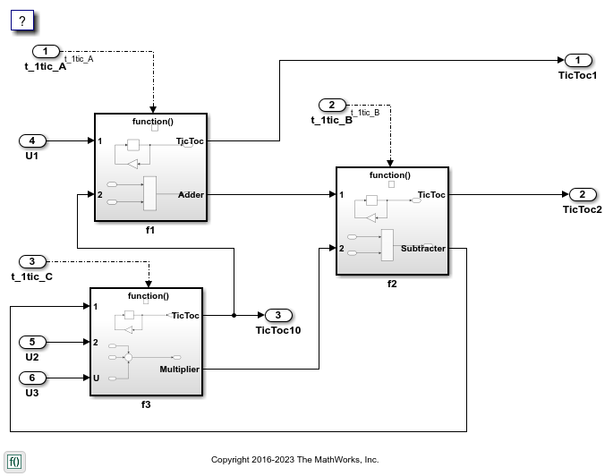
Model CppClassFunctions contains function-call subsystems f1, f2, and f3 for exporting functions.
open_system('CppClassFunctions')
Create Test Harness Model for Simulation
When you export functions, the generated code does not include a scheduler. Create a test harness model to handle scheduling during simulation. Do not use the test harness model to generate code that you deploy.
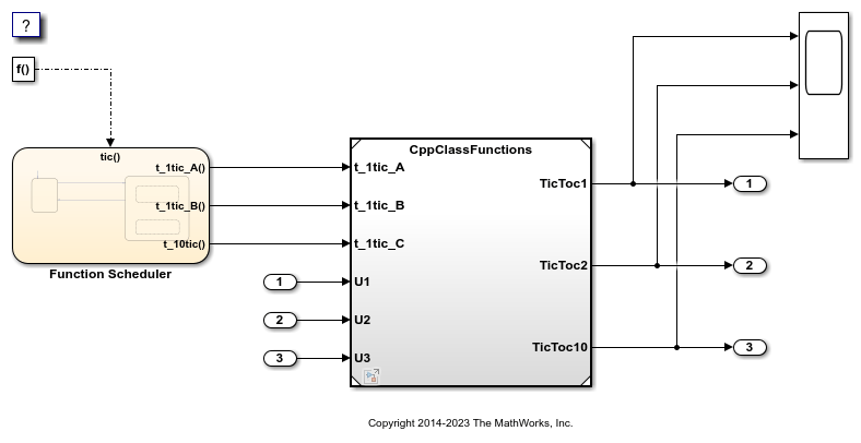
Model CppClassFunctionsHarness is a test harness. The model provides function-call signals to other models in this example to schedule the model contents.
open_system('CppClassFunctionsHarness')
Simulate the Test Harness Model
Verify that the model containing the functions that you want to export is executed as you expect by simulating the test harness model. For example, simulate CppClassFunctionsHarness.
sim('CppClassFunctionsHarness')
Generate Function Code and Report
Generate code and a code generation report for the functions that you want to export. For example, generate code for CppClassFunctions.
slbuild('CppClassFunctions')
Searching for referenced models in model 'CppClassFunctions'.
Total of 1 models to build.
Starting build procedure for: CppClassFunctions
Successful completion of build procedure for: CppClassFunctions
Build Summary
Top model targets:
Model Build Reason Status Build Duration
CppClassFunctions Information cache folder or artifacts were missing. Code generated and compiled. 0h 0m 16.894s
1 of 1 models built (0 models already up to date) Build duration: 0h 0m 18.193s
Review Generated Code
From the code generation report, review the generated code.
ert_main.cppis an example main program (execution framework) for the model. This code shows how to call the exported functions. The code also shows how to initialize and execute the generated code.CppClassFunctions.cppcalls the initialization function, includingInitialize Function, and exported functions for model subsystem componentsf1,f2, andf3.CppClassFunctions.hdeclares model data structures and a public interface to the exported entry-point functions and data structures.rtwtypes.hdefines data types, structures, and macros that the generated code requires.
Write Interface Code
Open and review the Code Interface Report. To write the interface code for your execution framework, use the information in that report.
- Include the generated header files by adding directives
#include CppClassFunctions.hand#include rtwtypes.h. - Write input data to the generated code for model Inport blocks.
- Call the generated entry-point functions.
- Read data from the generated code for model Outport blocks.
Input ports:
rtU.U1of typereal_Twith dimension 1rtU.U2of typereal_Twith dimension 1rtU.U3of typereal_Twith dimension 1
Entry-point functions:
- Initialize entry-point function,
void initialize(void). At startup, call this function once. - Exported function,
void t_1tic_A(void). Call this function as needed. - Exported function,
void t_1tic_B(void). Call this function as needed. - Exported function,
void t_1tic_C(void). Call this function as needed.
Output ports:
rtY.TicToc1of typeint8_Twith dimension [2]rtY.TicToc2of typeint8_Twith dimension [2]rtY.TicToc10of typeint8_Twith dimension 1
Close Example Models
bdclose('CppClassFunctionsHarness') bdclose('CppClassFunctions')
More About
- Generate Component Source Code for Export to External Code Base
- Deploy Applications to Target Hardware
- Customize Code Organization and Format
- Generate Code for Simulink Function and Function Caller
Generate Code for Export-Function Subsystems
- Specify a Custom Initialize Function Name
- Specify a Custom Description
- Optimize Code Generated for Export-Function Subsystems
To generate code for an export-function subsystem:
- Verify that the subsystem for which you are generating code satisfies exporting requirements.
- In the Configuration Parameters dialog box:
- Set the parameter System target file to an ERT-based system target file, such as
ert.tlc. - If you want a SIL block with the generated code, for verification purposes, set model configuration parameter Create block to
SIL. - Click OK orApply.
- Set the parameter System target file to an ERT-based system target file, such as
- Right-click the subsystem block and select from the context menu.
The operation creates and builds a new model,_`subsystem`_.slx, that contains the content of the original subsystem and creates aScratchModelthat contains a Model block. This block references the newly created_`subsystem`_.slxmodel.
The code generator produces code and places it in the working folder.
If you set Create block toSILin step 2b, Simulink opens a new window that contains an S-function block that represents the generated code. This block has the same size, shape, and connectors as the original subsystem.
Code generation and optional block creation are now complete. You can test and use the code and optional block as you do for generated ERT code and S-function block. For optional workflow tasks, see Specify a Custom Initialize Function Name and Specify a Custom Description.
Specify a Custom Initialize Function Name
You can specify a custom name for the initialize function of your exported function as an argument to the slbuild command. The command takes the following form:
blockHandle = slbuild('subsystem', 'Mode', 'ExportFunctionCalls',.. 'ExportFunctionInitializeFunctionName', 'fcnname')
_`fcnname`_ specifies the function name. For example, if you specify the name 'myinitfcn', the build process emits code similar to:
/* Model initialize function */ void myinitfcn(void){ ... }
Specify a Custom Description
You can enter a custom description for an exported function by using the Block Properties dialog box of an Inport block.
- Right-click the Inport block that drives the control port of the subsystem for which you are exporting code.
- Select Properties.
- In the General tab, in theDescription field, enter your descriptive text.
During function export, the text you enter is emitted to the generated code in the header for the Inport block. For example, if you open a model and enter a description in the Block Properties dialog box for a port f1, the code generator produces code that is similar to:
/*
- Block description for RootInportFunctionCallGenerator generated from '<Root>/f1':
- My custom description */ void t_1tic_A(void) { ... }
Optimize Code Generated for Export-Function Subsystems
To optimize the code generated for an export-function subsystem, specify a separate storage class for each input signal and output signal that crosses the boundary of the subsystem.
For each function-call subsystem that you are exporting:
- Right-click the subsystem.
- From the context menu, choose Block Parameters (Subsystem).
- Select the Code Generation tab.
- Set Function packaging to
Auto. - Click OK or Apply.