Nested Structures of Signals - MATLAB & Simulink (original) (raw)
You can create nested structures of signal data in the generated code.
C Construct
typedef struct { double signal1; double signal2; double signal3; } B_struct_type;
typedef struct { double signal1; double signal2; } C_struct_type;
typedef struct { B_struct_type subStruct_B; C_struct_type subStruct_C; } A_struct_type;
Procedure
To represent a structure type in a model, create a Simulink.Bus object. Use the object as the data type of buses in your model.
To nest a structure inside another structure, use a bus object as the data type of an element in another bus object.
1. Create the ex_signal_nested_struct model with Gain blocks, Bus Creator blocks, and a Unit Delay block. The Gain and Unit Delay blocks make the structure more identifiable in the generated code.
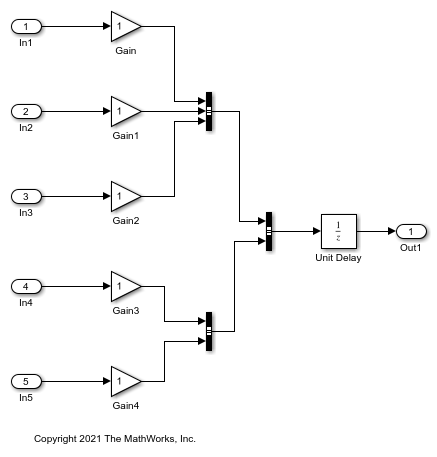
To configure a Bus Creator block to accept three inputs, in the block dialog box, set Number of inputs to 3.
2. In the toolstrip, on the Modeling tab, in the Design gallery, click Type Editor.
3. In the Type Editor, create three Simulink.Bus objects:
- A bus object named
A_struct_typewith two elements namedsubStruct_BandsubStruct_C - A bus object named
B_struct_typewith three elements namedsignal1,signal2, andsignal3 - A bus object named
C_struct_typewith two elements namedsignal1andsignal2
The bus object named A_struct_type represents the top-level structure type that you want the generated code to use.
For information on how to create bus objects and their elements, see Type Editor.
4. In the A_struct_type object, use the other bus objects as data types.
- For the
subStruct_Belement, set DataType toBus: B_struct_type. - For the
subStruct_Celement, set DataType toBus: C_struct_type.

Each element in A_struct_type uses another bus object as a data type. These elements represent substructures.
5. In the dialog box of the Bus Creator block that receives signals from three Gain blocks:
- Set Output data type to
Bus: B_struct_type. - Select Output as nonvirtual bus.
6. In the dialog box of the other subordinate Bus Creator block:
- Set Output data type to
Bus: C_struct_type. - Select Output as nonvirtual bus.
7. In the last Bus Creator block dialog box:
- Set Output data type to
Bus: A_struct_type. - Select Output as nonvirtual bus.
8. Open the Simulink Coder app. In the C Code tab, select Code Interface > Individual Element Code Mappings.
9. Open the Signals/States tab. In the model, select the output signal of the A_struct_type Bus Creator block, which feeds the Unit Delay block. Click the Add selected signals to code mappings button in the Code Mappings editor.
10. For the added signal, set Storage Class to ExportedGlobal.
11. In the Property Inspector, set the Code > Identifier property to sig_struct_var. The output of the Bus Creator block appears in the generated code as a separate global structure variable named sig_struct_var.
12. Generate code from the model.
Results
The generated header file ex_signal_nested_struct_types.h defines the structure types. Each structure type corresponds to a Simulink.Bus object.
typedef struct { real_T signal1; real_T signal2; real_T signal3; } B_struct_type;
typedef struct { real_T signal1; real_T signal2; } C_struct_type;
typedef struct { B_struct_type subStruct_B; C_struct_type subStruct_C; } A_struct_type;
The generated source file ex_signal_nested_struct.c allocates memory for the global structure variable sig_struct_var. By default, the name of the A_struct_type Bus Creator block is Bus Creator2.
/* Exported block signals / A_struct_type sig_struct_var; / '/Bus Creator2' */
In the same file, in the model step function, the algorithm accesses sig_struct_var and the fields of sig_struct_var.