Prepare a Model for Code Generation - MATLAB & Simulink (original) (raw)
Main Content
Several standard methods are available for setting up a model to generate specific C constructs in your code. For preparing your model for code generation, some of these methods include: configuring signals and ports, initializing states, and setting up configuration parameters for code generation. Depending on the components of your model, some of these methods are optional. Methods for configuring a model to generate specific C constructs are organized by category, for example, the Control Flow category includes constructsif-else, switch, for, andwhile. Refer to the name of a construct to see how you should configure blocks and parameters in your model. Different modeling methodologies are available, such as Simulink® blocks, Stateflow® charts, and MATLAB Function blocks, to implement a C construct.
Model examples in Modeling Patterns for C Code Constructs have the following naming conventions:
| Model Components | Naming Convention |
|---|---|
| Inputs | u1, u2, u3, and so on |
| Outputs | y1, y2, y3, and so on |
| Parameters | p1, p2, p3, and so on |
| States | x1, x2, x3, and so on |
Input ports are named to reflect the signal names that they propagate.
Configure Input Ports, Output Ports, and Arbitrary Signals
- Create a model in Simulink. For more information, see Interactive Model Editing.
- On the tab, click . You can also use the keyboard shortcut Ctrl +Shift + E.
- Set the Change view drop-down list to
Design. - Use the Storage Class column to apply a storage class to the signal.
For example, apply the storage classExportedGlobal, which makes the signal appear in the generated code as a separate global variable. The variable has the same name as the signal in the model.
Initialize and Configure States
- In the Model Data Editor, on the States tab, use theInitial Value column to specify initial values for a block state (such as the state of a Unit Delay block).
- Set the Change view drop-down list to
Code. - Use the Name column to give the state a name.
- Use the Storage Class column to apply a storage class to the state.
Set Up Configuration Parameters for Code Generation
- On the tab, click to open the Configuration Parameters dialog box. You can also use the keyboard shortcut Ctrl +E.
Open the Configuration Parameter dialog box by selecting > . - Open the Solver pane and select
- Solver type:
Fixed-Step - Solver:
discrete (no continuous states)
- Solver type:
- Open the pane, and set Default parameter behavior to
Inlined. - Open the Code Generation pane, and specify
ert.tlcas the System Target File. - Clear Generate makefile.
- Select Generate code only.
- Enable the HTML report generation by opening the > pane and selecting Create code generation report andOpen report automatically. Click the horizontal ellipsis and, under Advanced parameters, selectCode-to-model. Enabling the HTML report generation is optional.
- Click Apply and then OK to exit.
Set Up an Example Model With a Stateflow Chart
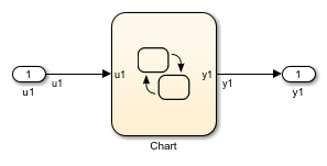
Follow this general procedure to create a simple model containing a Stateflow chart.
- From the Stateflow > Chart library, add a Stateflow chart to your model.
- Add Inport blocks and Outport blocks according to the example model.
- Open the Stateflow Editor by performing one of the following:
- Double-click the Stateflow chart.
- Press Ctrl+R.
- Add inputs to you chart as described in Add Stateflow Data (Stateflow).
- Specify the Name
(u1, u2, ...)and the Type (Inherit: Same as Simulink) for each input, unless specified differently in the example. - Add outputs to you chart as described in Add Stateflow Data (Stateflow).
- Specify the Name
(y1, y2, ...)and Type (Inherit: Same as Simulink) for each output, unless specified differently in the example. - In the Stateflow Editor, create the Stateflow diagram specific to the example.
- The inputs and outputs appear on the chart in your model.
- Connect the Inport and Outport blocks to the Stateflow Chart.
- Configure the input and output signals; see Configure Input Ports, Output Ports, and Arbitrary Signals.
Set Up an Example Model With a MATLAB Function Block
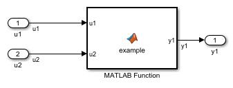
- Add the number of Inport and Outport blocks according to a C construct example included in this chapter.
- From the Simulink User-defined Functions library drag a MATLAB Function block into the model.
- Double-click the block. The MATLAB Function Block Editor opens. Edit the function to implement your application.
- On the tab, click and close the MATLAB Function Block Editor.
- Connect the Inport and Outport blocks to the MATLAB Function block. See Configure Input Ports, Output Ports, and Arbitrary Signals.
- Save your model.