Cos - Compute cosine operation using CORDIC approximation method and simulate with
latency - Simulink ([original](https://www.mathworks.com/help/hdlcoder/ref/cos.html)) ([raw](?raw))Compute cosine operation using CORDIC approximation method and simulate with latency
Since R2020b
Description
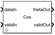
The Cos block computes the cosine of input signal by using the coordinate rotation digital computer (CORDIC) approximation method. For more information, see CORDIC approximation method in Algorithms. The block has control signals that indicate whether the input and output data are valid. You can also specify the number of iterations of the algorithm and the latency strategy.
To use this block in your Simulink® model, open the HDLMathLib library by entering this command in the MATLAB® Command Window:
open_system('HDLMathLib')
You can simulate the Sin block with latency. For more information, Latency Considerations.
Examples
Ports
Input
Input data signal to compute cosine function, specified as a scalar or vector. The input value ranges from -2π to 2*π.
Data Types: int8 | int16 | int32 | int64 | uint8 | uint16 | uint32 | uint64 | Boolean | fixed point | bus
Input control signal that indicates whether the input signal is valid, specified as a scalar.
Data Types: Boolean
Output
Output data signal that is the cosine of the input signal, returned as a scalar or vector.
Data Types: int8 | int16 | int32 | int64 | uint8 | uint16 | uint32 | uint64 | Boolean | fixed point | bus
Output control signal that indicates whether output signal is valid, returned as a scalar.
Data Types: Boolean
Parameters
Specify the number of iterations for CORDIC algorithm.
Programmatic Use
| Block Parameter:iter |
|---|
| Type: character vector |
| Values: Integer values |
| Default: '11' |
Specify whether to use minimum, maximum, custom, or zero latency. For more information, see Latency Strategy.
To use custom latency for the block, set the Latency strategy toCustom and enter the latency value in the Custom latency field.
You can also control the number of pipeline stages for the iterative algorithm. To customize the latency for iterative algorithm, set theLatency strategy to Custom(PerIteration) and enter the iterations per pipeline value in the IterationsPerPipeline field. (since R2025a)
Programmatic Use
| Block Parameter:latencyMode | |||
|---|---|---|---|
| Type: character vector | |||
| Values: 'Max' |'Min' | 'Custom' | 'Custom(PerIteration)' | 'Zero' |
| Default: 'Max' |
Specify the custom latency value. The latency must be a nonnegative integer in the range [0, _L_], where L is the maximum latency value of Cos block. For more information, see CustomLatency.
Dependency
To enable this parameter, set Latency strategy toCustom.
Programmatic Use
| Block Parameter:customLatencyValue |
|---|
| Type: Integer |
| Values: 0 to Max latency |
| Default: 0 |
Since R2025a
Specify the iterations to use per each pipeline stage in the algorithm.
Dependency
To enable this parameter, set Latency strategy toCustom(PerIteration).
Programmatic Use
| Block Parameter:iterationsPerPipelineValue |
|---|
| Type: Integer |
| Values: Positive integer |
| Default: 1 |
Algorithms
CORDIC is an acronym for coordinate rotation digital computer. The Givens rotation-based CORDIC algorithm is one of the most hardware-efficient algorithms available because it requires only iterative shift-add operations (see References). The CORDIC algorithm eliminates the need for explicit multipliers. Using CORDIC, you can calculate various functions such as sine, cosine, arc sine, arc cosine, arc tangent, and vector magnitude. You can also use this algorithm for divide, square root, hyperbolic, and logarithmic functions.
Increasing the number of CORDIC iterations can produce more accurate results, but doing so increases the expense of the computation and adds latency.
You can simulate the Cos block with latency. This block is a masked subsystem that contains a MATLAB Function block,LumpLatency. The subsystem uses this MATLAB Function block to compute the latency based on the Number of iterations. To view the function that computes the latency of the block, open the LumpLatency block in the masked subsystem. To view inside the mask, click the ⇩ icon on the block.
This table shows how the block calculates the latency based on the setting of theLatency strategy parameter:
| Latency Strategy | Latency Value (L) |
|---|---|
| Max | Uses maximum latency by using the equation L =N + 1, where N is the value of theNumber of iterations parameter. |
| Min | Uses minimum latency by using the equation L = 2 +ceil((N -1) / 3). |
| Custom | Specifies a custom latency value. To specify the latency, enter a value between zero and the maximum latency in the Custom latency parameter. For more information, see Custom latency. |
| Custom(PerIteration) | Use this setting to control the pipeline stages for the iterative algorithm.Specify the number of pipeline stages per iteration using the IterationsPerPipeline parameter. The block uses the equation L = 1 + ceil(N /K), where K is the value of theIterationsPerPipeline parameter. |
| Zero | The latency of the block is 0. |
The Cos block uses pipelined architectures to implement the CORDIC-based cosine algorithm. By default, the block uses the maximum latency, which depends on theNumber of iterations parameter. The block performs a single iteration per pipeline stage. For example, if you set the Number of iterations to15, the latency of the block is 16, based on the latency equation in Latency Considerations. When you increase number of iterations, the latency of the block also increases.
You can customize the latency for the iterative algorithm by setting Latency strategy to Custom(PerIteration), which allows you to control the number of iterations per pipeline stages. For example, if you set theNumber of iterations to 15 and you want the block to perform the iterations in three pipeline stages, then set theIterationsPerPipeline to 15/3 = 5. By using theCustom(PerIteration) latency strategy, the latency of the block reduces to 4.
References
[1] Volder, Jack E., “The CORDIC Trigonometric Computing Technique.” IRE Transactions on Electronic Computers EC-8 (1959); 330–334.
[2] Andraka, Ray “A Survey of CORDIC Algorithm for FPGA Based Computers.”Proceedings of the 1998 ACM/SIGDA Sixth International Symposium on Field Programmable Gate Arrays. Feb. 22–24 (1998): 191–200.
[3] Walther, J.S., “A Unified Algorithm for Elementary Functions,” Proceedings of the Spring Joint Computer Conference, May 18-20, 1971: 379–386.
[4] Schelin, Charles W., “Calculator Function Approximation,” The American Mathematical Monthly 90, no. 5 (1983): 317–325.
Extended Capabilities
The block supports HDL code generation using HDL Coder™. HDL Coder provides additional configuration options that affect HDL implementation and synthesized logic.
HDL Architecture
| Architecture | Description |
|---|---|
| Module (default) | Generate code for the subsystem and the blocks within the subsystem. |
| BlackBox | Generate a black box interface. The generated HDL code includes only the input/output port definitions for the subsystem. Therefore, you can use a subsystem in your model to generate an interface to existing, manually written HDL code. The black-box interface generation for subsystems is similar to the Model block interface generation without the clock signals. |
| No HDL | Remove the subsystem from the generated code. You can use the subsystem in simulation, however, treat it as a “no-op” in the HDL code. |
HDL Block Properties
| General | |
|---|---|
| AdaptivePipelining | Automatic pipeline insertion based on the synthesis tool, target frequency, and multiplier word-lengths. The default is inherit. See alsoAdaptivePipelining. |
| BalanceDelays | Detects introduction of new delays along one path and inserts matching delays on the other paths. The default is inherit. See also BalanceDelays. |
| ClockRatePipelining | Insert pipeline registers at a faster clock rate instead of the slower data rate. The default is inherit. See also ClockRatePipelining. |
| ConstrainedOutputPipeline | Number of registers to place at the outputs by moving existing delays within your design. Distributed pipelining does not redistribute these registers. The default is0. For more details, see ConstrainedOutputPipeline. |
| DistributedPipelining | Pipeline register distribution, or register retiming. The default is inherit. See also DistributedPipelining. |
| DSPStyle | Synthesis attributes for multiplier mapping. The default is none. See also DSPStyle. |
| FlattenHierarchy | Remove subsystem hierarchy from generated HDL code. The default is inherit. See also FlattenHierarchy. |
| InputPipeline | Number of input pipeline stages to insert in the generated code. Distributed pipelining and constrained output pipelining can move these registers. The default is0. For more details, see InputPipeline. |
| OutputPipeline | Number of output pipeline stages to insert in the generated code. Distributed pipelining and constrained output pipelining can move these registers. The default is0. For more details, see OutputPipeline. |
| SharingFactor | Number of functionally equivalent resources to map to a single shared resource. The default is 0. See also Resource Sharing. |
| StreamingFactor | Number of parallel data paths, or vectors, that are time multiplexed to transform into serial, scalar data paths. The default is 0, which implements fully parallel data paths. See also Streaming. |
Target Specification
This block cannot be the DUT, so the block property settings in the Target Specification tab are ignored.
Limitations
- You cannot use this block in a Synchronous Subsystem block.
- The block does not support resource sharing optimization.
Version History
Introduced in R2020b
You can control the pipeline stages for iterative algorithms by setting theLatencyStrategy parameter HDL toCustom(PerIterations), then specifying the number of pipeline stages per iteration by using the IterationsPerPipeline parameter. Use this setting to control the pipeline stages in the generated code and optimize the design for speed and resource utilization.