Resettable Synchronous Subsystem - Represent resettable subsystem that has synchronous reset and enable
behavior - Simulink ([original](https://www.mathworks.com/help/hdlcoder/ref/resettablesynchronoussubsystem.html)) ([raw](?raw))Represent resettable subsystem that has synchronous reset and enable behavior
Libraries:
HDL Coder / HDL Subsystems
Description
The Resettable Synchronous Subsystem uses the State Control block in Synchronous mode with the Resettable Subsystem block. For subsystem blocks with state, the State Control block in Synchronous mode provides efficient reset and enable simulation behavior on hardware.
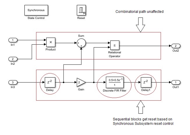
The reset port in the Resettable Synchronous Subsystem block adds reset capability to blocks inside the subsystem that have state. This includes blocks that need not have an external reset port capability, such as filters, Stateflow® Chart, and MATLAB Function blocks. For HDL code generation, theReset trigger type of the Reset port is set tolevel hold by default.
Ports
Input
Data Types: single | double | int8 | int16 | int32 | int64 | uint8 | uint16 | uint32 | uint64 | Boolean | fixed point | enumerated | bus
Output
Data Types: single | double | int8 | int16 | int32 | int64 | uint8 | uint16 | uint32 | uint64 | Boolean | fixed point | enumerated | bus
Parameters
Select how to display port labels on the Synchronous Subsystem block icon.
none
Do not display port labels.
FromPortIcon
If the corresponding port icon displays a signal name, display the signal name on the Subsystem block. Otherwise, display the port block name or the port number if the block name is a default name.
FromPortBlockName
Display the name of the corresponding port block on theSubsystem block.
SignalName
If the signal connected to the port is named, display the name of the signal on the Subsystem block. Otherwise, display the name of the corresponding port block.
Programmatic Use
| Parameter:ShowPortLabels | ||
|---|---|---|
| Type: character vector | ||
| Value: 'FromPortIcon' |'FromPortBlockName' | 'SignalName' | 'none' |
| Default:'FromPortIcon' |
Control user access to the contents of the subsystem.
Settings
Default: ReadWrite
ReadWrite
Enables opening and modification of subsystem contents.
ReadOnly
Enables opening but not modification of the subsystem. If the subsystem resides in a block library, you can create and open links to the subsystem and can make and modify local copies of the subsystem but cannot change the permissions or modify the contents of the original library instance.
NoReadOrWrite
Disables opening or modification of subsystem. If the subsystem resides in a library, you can create links to the subsystem in a model but cannot open, modify, change permissions, or create local copies of the subsystem.
Programmatic Use
| Parameter:Permissions | |
|---|---|
| Type: character vector | |
| Value: 'ReadWrite' |'ReadOnly' | 'NoReadOrWrite' |
| Default:'ReadWrite' |
Enter name of a function to be called if an error occurs while Simulink software is executing the subsystem.
Simulink software passes two arguments to the function: the handle of the subsystem and a character vector that specifies the error type. If no function is specified, Simulink software displays a generic error message if executing the subsystem causes an error.
Programmatic Use
| Parameter:ErrorFcn |
|---|
| Type: character vector |
| Value: '' |'' |
| Default: '' |
Select whether to resolve names of workspace variables referenced by this subsystem.
For more information, see Symbol Resolution and Symbol Resolution Process.
All
Resolve all names of workspace variables used by this subsystem, including those used to specify block parameter values and Simulink data objects (for example, Simulink.Signal objects).
ExplicitOnly
Resolve only names of workspace variables used to specify block parameter values, data store memory (where no block exists), signals, and states marked as “must resolve”.
None
Do not resolve workspace variable names.
Programmatic Use
| Parameter:PermitHierarchicalResolution | |
|---|---|
| Type: character vector | |
| Value: 'All' |'ExplicitOnly' | 'None' |
| Default: 'All' |
Select the code format to be generated for an atomic (nonvirtual) subsystem.
Auto
Simulink Coder™ chooses the optimal format for you based on the type and number of instances of the subsystem that exist in the model.
Inline
Simulink Coder inlines the subsystem unconditionally.
Nonreusable function
Simulink Coder software explicitly generates a separate function in a separate file. Subsystems with this setting generate functions that might have arguments depending on the Function interface parameter setting. You can name the generated function and file using parameters Function name and File name (no extension). These functions are not reentrant.
Reusable function
Simulink Coder software generates a function with arguments that allows reuse of subsystem code when a model includes multiple instances of the subsystem.
This option also generates a function with arguments that allows subsystem code to be reused in the generated code of a model reference hierarchy that includes multiple instances of a subsystem across referenced models. In this case, the subsystem must be in a library.
Programmatic Use
| Parameter:RTWSystemCode | ||
|---|---|---|
| Type: character vector | ||
| Value: 'Auto' |'Inline' | 'Nonreusable function' | 'Reusable function' |
| Default: 'Auto' |
Extended Capabilities
HDL Coder™ provides additional configuration options that affect HDL implementation and synthesized logic.
HDL Architecture
| Architecture | Description |
|---|---|
| Module (default) | Generate code for the subsystem and the blocks within the subsystem. |
| BlackBox | Generate a black box interface. The generated HDL code includes only the input/output port definitions for the subsystem. Therefore, you can use a subsystem in your model to generate an interface to existing, manually written HDL code. The black-box interface generation for subsystems is similar to the Model block interface generation without the clock signals. |
| No HDL | Remove the subsystem from the generated code. You can use the subsystem in simulation, however, treat it as a “no-op” in the HDL code. |
HDL Block Properties
| General | |
|---|---|
| AdaptivePipelining | Automatic pipeline insertion based on the synthesis tool, target frequency, and multiplier word-lengths. The default is inherit. See alsoAdaptivePipelining. |
| ClockRatePipelining | Insert pipeline registers at a faster clock rate instead of the slower data rate. The default is inherit. See also ClockRatePipelining. |
| ConstrainedOutputPipeline | Number of registers to place at the outputs by moving existing delays within your design. Distributed pipelining does not redistribute these registers. The default is0. For more details, see ConstrainedOutputPipeline. |
| DistributedPipelining | Pipeline register distribution, or register retiming. The default is inherit. See also DistributedPipelining. |
| DSPStyle | Synthesis attributes for multiplier mapping. The default is none. See also DSPStyle. |
| FlattenHierarchy | Remove subsystem hierarchy from generated HDL code. The default is inherit. See also FlattenHierarchy. |
| InputPipeline | Number of input pipeline stages to insert in the generated code. Distributed pipelining and constrained output pipelining can move these registers. The default is0. For more details, see InputPipeline. |
| OutputPipeline | Number of output pipeline stages to insert in the generated code. Distributed pipelining and constrained output pipelining can move these registers. The default is0. For more details, see OutputPipeline. |
| SharingFactor | Number of functionally equivalent resources to map to a single shared resource. The default is 0. See also Resource Sharing. |
| StreamingFactor | Number of parallel data paths, or vectors, that are time multiplexed to transform into serial, scalar data paths. The default is 0, which implements fully parallel data paths. See also Streaming. |
If this block is not the DUT, the block property settings in the Target Specification tab are ignored. In the HDL Workflow Advisor, if you use theIP Core Generation workflow, these target specification block property values are saved with the model. If you specify these target specification block property values using hdlset_param, when you open HDL Workflow Advisor, the fields are populated with the corresponding values.
| Target Specification | |
|---|---|
| AdditionalTargetInterfaces | Additional target interfaces, specified as a character vector. To save this block property on the model, in the Set Target Interface task of the IP Core Generation workflow, corresponding to the DUT ports that you want to add more interfaces, select Add more.... You can then add more interfaces in the Add New Target Interfaces dialog box. Specify the type of interface, number of additional interfaces, and a unique name for each additional interface. Values: '' (default) | cell array of character vectors Example:'{{'AXI4-Stream','InterfaceID','AXI4-Stream1'}}' |
| ProcessorFPGASynchronization | Processor/FPGA synchronization mode, specified as a character vector. To save this block property on the model, specify the Processor/FPGA Synchronization in the Set Target Interface task of the IP Core Generation workflow.Values: Free running (default) | Coprocessing - blockingExample: 'Free running' |
| TestPointMapping | To save this block property on the model, specify the mapping of test point ports to target platform interfaces in the Set Target Interface task of the IP Core Generation workflow.Values: '' (default) | cell array of character vectorsExample: '{{'TestPoint','AXI4-Lite','x"108"'}}' |
| TunableParameterMapping | To save this block property on the model, specify the mapping of tunable parameter ports to target platform interfaces in the Set Target Interface task of the IP Core Generation workflow.Values: '' (default) | cell array of character vectorsExample: '{{'myParam','AXI4-Lite','x"108"'}}' |
| AXI4RegisterReadback | To save this block property on the model, specify whether you want to enable readback on AXI4 subordinate write registers in the Generate RTL Code and IP Core task of the IP Core Generation workflow. To learn more, see Model Design for AXI4 Slave Interface Generation.Values: 'off' (default) |'on' |
| AXI4SlaveIDWidth | To save this block property on the model, specify the number of AXI manager interfaces that you want to connect the DUT IP core to by using the AXI4 Slave ID Width setting in the Generate RTL Code and IP Core task of the IP Core Generation workflow. To learn more, see Define Multiple AXI Master Interfaces in Reference Designs to Access DUT AXI4 Slave Interface. Values: 'off' (default) |'on' |
| RegisterInterfaceReadPipeline | To save this block property on the model, Specify the number of pipeline stages to insert in the read address decoder path by using theRegister interface read pipeline setting in the Generate RTL Code and IP Core task of the IP Core Generation workflow. To learn more, see Model Design for AXI4 Slave Interface Generation. Values: 0 (default) | character vector |
| GenerateDefaultAXI4Slave | To save this block property on the model, specify whether you want to disable generation of default AXI4 subordinate interfaces in the Generate RTL Code and IP Core task of the IP Core Generation workflow.Values: 'on' (default) |'off' |
| IPCoreAdditionalFiles | Verilog®, SystemVerilog, or VHDL® files for black boxes in your design. Specify the full path to each file, and separate file names with a semicolon (;).You can set this property in the HDL Workflow Advisor, in the Additional source files field.Values: '' (default) | character vectorExample: 'C:\myprojfiles\led_blinking_file1.vhd;C:\myprojfiles\led_blinking_file2.vhd;' |
| IPCoreName | IP core name, specified as a character vector.You can set this property in the HDL Workflow Advisor, in the IP core name field. If this property is set to the default value, the HDL Workflow Advisor constructs the IP core name based on the name of the DUT.Values: '' (default) | character vectorExample: 'my_model_name' |
| IPCoreVersion | IP core version number, specified as a character vector.You can set this property in the HDL Workflow Advisor, in the IP core version field. If this property is set to the default value, the HDL Workflow Advisor sets the IP core version.Values: '' (default) | character vectorExample: '1.3' |
| IPDataCaptureBufferSize | FPGA Data Capture buffer size, specified as a character vector. Use FPGA Data Capture to observe signals in a design when running on an FPGA. The buffer size uses values that are 128*2^n, where n is an integer. By default, the buffer size is 128 (n=0). The maximum value of n is 13, which means that the maximum value for buffer size is 1048576 (=128*2^13). Values: '' (default) | character vector Example: '1.3' |
Restrictions
- You cannot use the State Control block inClassic mode or remove the State Control block from the Resettable Synchronous Subsystem block.
- The Reset trigger type of the Reset port inside the subsystem must be set to
level hold. - A Delay block with nonvirtual bus input signals inside aResettable Synchronous Subsystem is not supported if you enable optimizations on the subsystem.
- HDL code generation supports only boolean datatype at the Reset port.
- HDL Coder does not support these blocks inside a Resettable Synchronous Subsystem:
- Stateflow Charts
- All RAM blocks or blocks that infer a RAM in the generated HDL code. The RAM blocks include:
* Single Port RAM
* Simple Dual Port RAM
* Dual Port RAM
* Dual Rate Dual Port RAM
* HDL FIFO
*hdl.RAMsystem object
DSP System Toolbox
- Biquad Filter
- NCO HDL Optimized
Communications Toolbox - Convolutional Encoder
- Viterbi Decoder
- PN Sequence Generator
- Integer-Output RS Decoder HDL Optimized
Vision HDL Toolbox - Demosaic Interpolator
- Edge Detector
- Histogram
- Image Filter, Median Filter, Bilateral Filter
- Line Memory
- Binary and Grayscale Morphology blocks
- Pixel Stream FIFO
Wireless HDL Toolbox - LTE Turbo Decoder and LTE Turbo Encoder
- LTE Convolutional Encoder
- LTE OFDM Demodulator and LTE OFDM Modulator
- NR Polar Encoder and NR Polar Decoder
- Viterbi Decoder
- FFT 1536
- RS Decoder
- OFDM Channel Estimator
- NR LDPC Encoder and NR LDPC Decoder
Version History
Introduced in R2016b