Synchronous Subsystem Behavior with the State Control Block - MATLAB & Simulink (original) (raw)
Main Content
What Is a State Control Block?
When you have blocks with state, and have enable or reset ports inside a subsystem, use the Synchronous mode of the State Control block to:
- Provide efficient enable and reset simulation behavior on hardware.
- Generate cleaner HDL code and use fewer resources on hardware.
You can add the State Control block to your Simulink® model at any level in the model hierarchy. How you set the State Control block affects the simulation behavior of other blocks inside the subsystem that have state.
- For synchronous hardware simulation behavior, set State control to
Synchronous. - For default Simulink simulation behavior, set State control to
Classic.
State Control Block Modes
| Functionality | Synchronous mode | Classic mode |
|---|---|---|
| State Control block setting | Default block setting when you add the block from the HDL Subsystems block library. | The simulation behavior is the same as a subsystem that does not use theState Control block. |
| Simulink simulation behavior Initialize method: Initializes states.Update method: Updates states.Output method: Computes output values. | The update method only updates states. The output method computes the output values at each time step.For example, when you have enabled subsystems, the output value changes when the enable signal is low as it processes new input values. The output value matches the output fromClassic mode when enable signal becomes high. | The update method updates states and computes the output values.For example, when you have enabled subsystems, the output value is held steady when the enable signal is low and changes only when the enable signal becomes high. |
| HDL simulation behavior | More efficient on hardware. | Less efficient on hardware. |
| HDL code generation behavior | Generated HDL code is cleaner and uses fewer resources on hardware.For example, when you have enabled subsystems, HDL Coder™ does not generate bypass registers for each state update and uses fewer hardware resources. | Generated HDL code is not as clean and uses more hardware resources.For example, when you have enabled subsystems, HDL Coder generates bypass registers for each state update and uses more resources. |
To learn more about when you can use the State Control block, see State Control.
Synchronous Badge for Subsystems by Using Synchronous Mode
To see if a subsystem in your Simulink model uses synchronous semantics:
- A symbol S is displayed on the subsystem to indicate synchronous behavior.
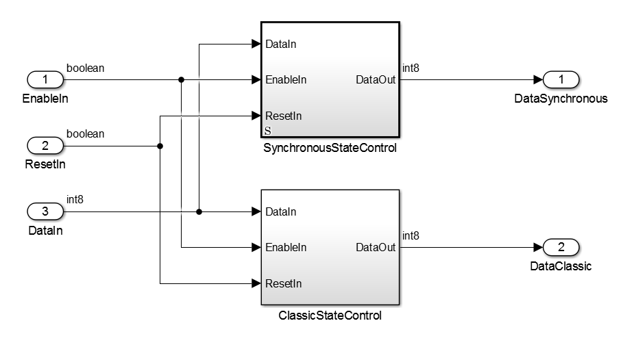
- If you double-click the SynchronousStateControl subsystem, a badge S is displayed in the Simulink editor to indicate that blocks inside the subsystem are using synchronous hardware semantics.
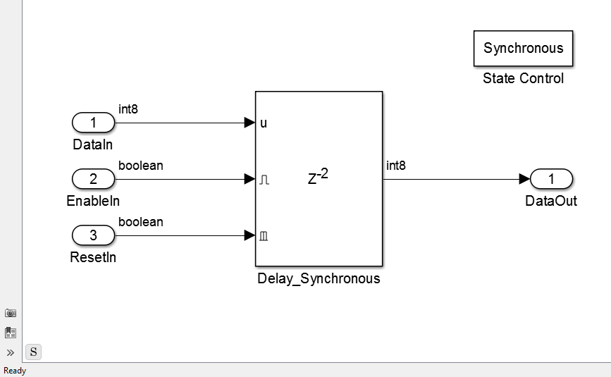
The SynchronousStateControl andClassicStateControl subsystems use a Delay block with an external reset and an enable port in Synchronous andClassic modes respectively.
Generate HDL Code with the State Control Block
The following table shows a comparison of the HDL code generated from theDelay block for Classic andSynchronous modes of the State Control block.
| Functionality | Synchronous mode | Classic mode |
|---|---|---|
| HDL code generation. Settings applied: Language:VerilogReset type:Synchronous | `timescale 1 ns / 1 ns module SynchronousStateControl ( clk, reset, enb, DataIn, EnableIn, ResetIn, DataOut ); input clk; input reset; input enb; input signed [7:0] DataIn; // int8 input EnableIn; input ResetIn; output signed [7:0] DataOut; // int8 reg signed [7:0] Delay_Synchronous_reg [0:1]; // sfix8 [2] wire signed [7:0] Delay_Synchronous_reg_next [0:1]; // sfix8 [2] wire signed [7:0] Delay_Synchronous_out1; // int8 always @(posedge clk) begin : Delay_Synchronous_process if (reset == 1'b1 | | ResetIn == 1'b1) begin Delay_Synchronous_reg[0] <= 8'sb00000000; Delay_Synchronous_reg[1] <= 8'sb00000000; end else begin if (enb && EnableIn) begin Delay_Synchronous_reg[0] <= Delay_Synchronous_reg_next[0]; Delay_Synchronous_reg[1] <= Delay_Synchronous_reg_next[1]; end end end assign Delay_Synchronous_out1 = Delay_Synchronous_reg[1]; assign Delay_Synchronous_reg_next[0] = DataIn; assign Delay_Synchronous_reg_next[1] = Delay_Synchronous_reg[0]; assign DataOut = Delay_Synchronous_out1; endmodule // SynchronousStateControl Generated HDL code is cleaner and requires fewer hardware resources as HDL Coder does not generate bypass registers.The update method only updates the states. |