Targeting FPGA & SoC Hardware Overview - MATLAB & Simulink (original) (raw)
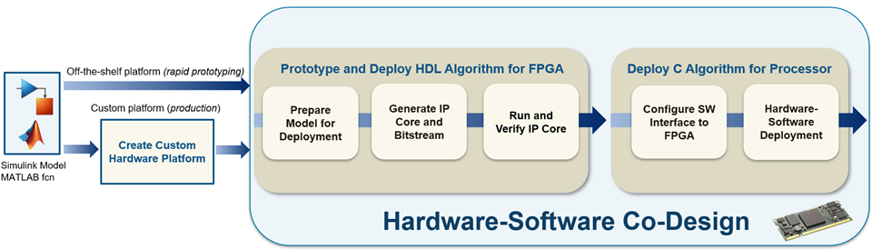
Target an FPGA or SoC device by following the steps that design and deploy your algorithm specifically on hardware. You start with a Simulink® model or MATLAB® function, choose a hardware platform to target, and follow the Hardware-Software Co-Design workflow. Explore the best ways to partition and deploy your design by iterating through these steps.
Choose your target platform. After modeling your design in Simulink or as a MATLAB function, decide what target platform you want to deploy your design to. Consider:
- Which type of device do you want to target: standalone FPGA, SoC device, or a platform that has a separate FPGA and processor?
Device Type Recommended Workflow Standalone FPGA If you are deploying only to an FPGA, use only the first part of the Hardware-Software Co-Design Workflow: Prototype and Deploy HDL Algorithm for FPGA. SoC Device To deploy a model to an SoC device, you need to partition the design to contain a hardware portion for the FPGA, and an embedded software portion for the processor, referred to as a hardware-software model. The FPGA requires a bitstream to alter its physical connections, the hardware part of the model, and the processor requires a new set of instructions in the form of an executable, the software part of the model. Simulink Real-Time™ FPGA I/O Modules This type of platform refers to a Speedgoat® target machine, which acts as a processor, and an FPGA IO module. You can program both the FPGA and processor using the targeting FPGA & SoC hardware steps. For more information, see IP Core Generation Workflow for Speedgoat Simulink-Programmable I/O Modules. - What stage of development are you in: rapid prototyping or production?
- For rapid prototyping, save development time by selecting a pre-existing target device that HDL Coder™ supports. You can then immediately get started using the Hardware-Software Co-Design workflow. See HDL Coder Supported Hardware.
- For production, or rapid prototyping with an unsupported device, create a custom hardware platform first, and then follow the Hardware-Software Co-Design workflow. See Create Custom Hardware Platform.
Hardware-Software Co-Design
The Hardware-Software Co-Design workflow is broken into two stages:
- Prototype and Deploy HDL Algorithm for an FPGA
Prepare your model for deployment on target hardware. HDL Coder generates an IP core and bitstream containing the generated HDL Code from your design to deploy to the FPGA of your device. You can then run and verify that the IP core is working on your target hardware. This stage can be used to target a standalone FPGA device, an SoC device, or platform that has a separate FPGA and processor. - Deploy C Algorithm for Processor
Configure the hardware-software interface by configuring the connection between the FPGA and processor generating C code for your processor.
Deploy your design that has been partitioned into hardware and embedded software components to run on a platform containing an FPGA and an embedded processor, such as an SoC device. The design consists of the DUT algorithm for which you generate an IP core and a bitstream containing your HDL code, and software components for which you generate embedded code to run on the processor. You use the generated software interface model and IP core that includes hardware interface components, such as AXI interfaces, to interface between the hardware and software components.
Prototype and Deploy HDL Algorithm for an FPGA
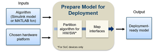
Prepare Model for Deployment
For the model and design of your algorithm to be deployable on your target device, these are the high-level tasks:
- Partition your design for hardware and software components of your target hardware, if you are using a platform containing a processor and an FPGA, such as an SoC device. You can partition your design to generate the hardware that targets the FPGA and the software that runs on the embedded processor.
- Map the inputs and outputs of your model to hardware interfaces, such as AXI4 interfaces, push buttons, and LEDs. The generated design can then communicate with the rest of the hardware system when it is deployed. For more information, see Target Platform Interfaces.
For an example on preparing a model for deployment, see Get Started with IP Core Generation from Simulink Model.
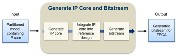
Generate IP Core and Bitstream
Once your design is prepared for deployment, you can use the HDL Workflow Advisor to:
- Generate a generic board-independent Xilinx® or Intel® HDL IP core. The IP core is a shareable and reusable HDL component that implements a specific function, typically an algorithm. An IP core consists of IP core definition files, HDL code generated for your algorithm, a C header file containing the register address map, and the IP core report. For an example, seeGenerate Board-Independent HDL IP Core from Simulink Model.
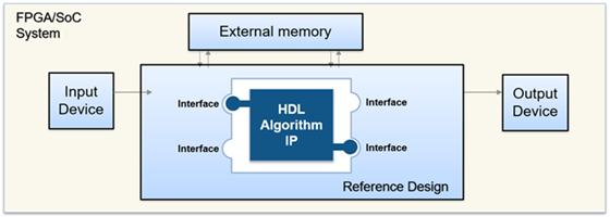
- Integrate the IP core into a reference design to target standalone FPGA boards or SoC platforms by using Xilinx Vivado® IP integrator or Intel Qsys. The reference design contains elements that the Intel or Xilinx software requires to deploy your design to the SoC platform, except for the custom IP core and embedded software that you generate from the hardware-software model. The reference design acts as a platform to build your algorithm on top of and abstracts your hardware platform so you can focus on your algorithm development. Once you have completed your algorithm development, HDL Coder enables you to package the algorithm as an IP core and fit it into the reference design.
- Generate a bitstream that contains your IP core for deployment on your target FPGA.
For an example on generating an IP core and bitstream, see Get Started with IP Core Generation from MATLAB Function.
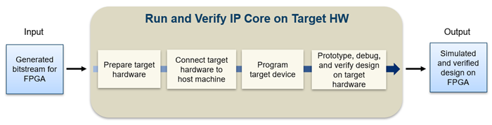
Run and Verify IP Core on Target Hardware
Run and verify the generated bitstream from your IP core design on your target hardware:
- Prepare your target hardware by connecting it to the host machine. If you are using a platform containing an FPGA and processor, such as an SoC device, download a Linux® image for the processor. For more information, seeGuided Hardware Setup for AMD Boards for Xilinx Zynq® Platforms or Guided Hardware Setup for Intel Boards for Intel SoC Devices.
- Establish a JTAG or Ethernet connection from your host machine to the target hardware.
- Program your target device.
- Prototype, debug, and verify your design on your target hardware by using one of these prototyping approaches:
- FPGA I/O. You can use the host interface model or host interface script generated by the HDL Workflow Advisor to communicate between your host PC, running MATLAB and Simulink, and the generated IP core deployed on your FPGA.
- AXI Manager
- FPGA Data Capture
- FPGA-in-the-Loop (FIL)
- Software Interface Model Generation, see Configure IP Core for Software Interface.
For an example, see Prototype Generated IP Core on Hardware using FPGA I/O.
Deploy C Algorithm for Processor
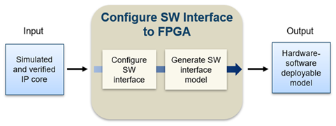
Configure Software Interface to FPGA
To target a complete hardware-software system, HDL Workflow Advisor generates a software interface model from your original Simulink model. The software interface model can be used for deployment to the on-board processor of your target platform. This model contains properly configured device drivers for the processor on-board your SoC device or target platform. If you are targeting an SoC device, this model is the second model required for the hardware-software design. The first model is the original model with your HDL algorithm to target the on-board FPGA. This software interface model targets your processor and communicates between the software deployed to the processor and the generated IP core deployed to the FPGA.
For more information, see Generate Software Interface Model to Probe and Rapidly Prototype HDL IP Core.
Hardware-Software Deployment
Generate C code (requires Embedded Coder®) from your software interface model and use external mode or processor-in-the-loop (PIL) mode to deploy and run your hardware-software model on target hardware. The deployable design for your SoC device consists of:
- A generated bitstream from your original model containing your HDL IP core.
- A software interface model containing configured device drivers to allow communication between your processor and FPGA and C code generation for embedded processor.
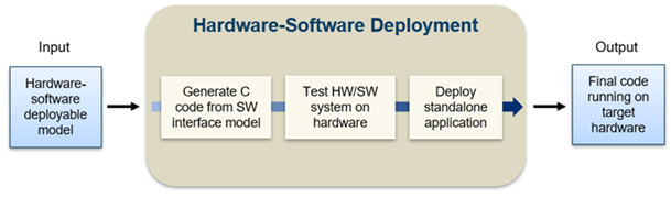
The deployment of your complete partitioned design into generated C code for the processor, from the software interface model, and a bitstream for the on-board FPGA, from your original model containing your IP core, enables you to run your algorithm on board an SoC or a Simulink Real-Time target machine that has FPGA I/O boards.
For an example, see Debug IP Core Using Hardware-Software Deployment.
Create Custom Hardware Platform
If there are no platforms already available for your hardware, you can define a custom hardware platform to use with the Hardware-Software Codesign workflow. A custom hardware platform creates flexibility to define your hardware system and deploy your design. For example, you can define a custom platform when deploying to production hardware. Creating a hardware platform consists of creating a new board definition to describe your hardware and creating one or more new reference designs for your board. You can also create new reference designs for an existing board.
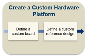
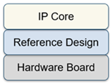
A reference design provides a level of abstraction between your algorithmic IP core and the hardware board, making it easier and more efficient to design an algorithm to deploy on hardware. The reference design acts as the layer between your algorithm and the hardware platform, which you can use to leverage resources within your hardware without having to model these specific hardware resources in your design. You can focus on your algorithm design without implementing low-level details of the hardware. You can also retarget your algorithm to different hardware. For example, you can retarget your algorithm design when you transition from an evaluation board used for prototyping to production hardware.
For more information, see Board and Reference Design Registration System.