Use Triggered Subsystem for Asynchronous Clock Domain - MATLAB & Simulink (original) (raw)
You can design a model for an asynchronous clock domain using a triggered subsystem. An asynchronous clock domain design operates at different clock regions whose clock rates are not integer multiples of one another. You can model an asynchronous clock domain design in Simulink® by using multiple triggered subsystems. You can use a trigger as a clock functionality to generate separate clock signals for each triggered subsystem.
Using a triggered subsystem and a trigger as a clock, you can design a model that has one of these characteristics:
- Clock regions driven by clocks whose rates are not integer multiples of one another.
- Clocks that run at the same rate but out of phase.
- Multiple clocks that operate at different rates.
- Multiple clocks and resets modeled using nested resettable subsystems.
- Synchronous and asynchronous external resets modeled using nested triggered and resettable subsystems.
Note
Using the trigger as a clock for triggered subsystems causes a one-cycle timing mismatch during testbench simulations. Run the generated HDL code on the hardware to verify your functionality with trigger as clock behavior.
Generate Multiple Clocks Using Trigger As Clock
This example shows how to model multiple clock signals using triggered subsystems. Using trigger as clock functionality in the triggered subsystem enables you to use trigger signal as a clock in your generated HDL code. You can model an asynchronous clock domain design in Simulink® by using multiple triggered subsystem and use trigger as a clock functionality to generate separate clock signal for each triggered subsystem.
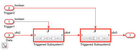
The model AsynchronousClockUsingTriggerAsClock has a DUT subsystem which contains a two Triggered Subsystem. Load and open the AsynchronousClockUsingTriggerAsClock model by running these commands:
load_system("AsynchronousClockUsingTriggerAsClock"); set_param("AsynchronousClockUsingTriggerAsClock",'SimulationCommand','Update') open_system("AsynchronousClockUsingTriggerAsClock/DUT");
To use trigger signal as clock in your generated HDL code, enable Use trigger signal as clock option in the HDL Code Generation > Global Settings > Ports tab of the configuration settings. Then, generate the HDL code for a DUT subsystem using makehdl command or HDL Coder™ app:
makehdl("AsynchronousClockUsingTriggerAsClock/DUT")
In the generated HDL code, HDL Coder generates two trigger ports for the DUT subsystem which are used as clock signal in the triggered subsystems.
     module DUT
             (Trigger1,
             Trigger2,
             Data,
             Out1);

     input   Trigger1;
     input   Trigger2;
     input   [1:0] Data;  // ufix2
     output  [7:0] Out1;  // uint8

     wire [7:0] Triggered_Subsystem1_out1;  // uint8
     wire [7:0] Triggered_Subsystem2_out1;  // uint8

     Triggered_Subsystem1 u_Triggered_Subsystem1 (.Trigger(Trigger1),
                                                 .In1(Data),  // ufix2
                                                 .Out1(Triggered_Subsystem1_out1)  // uint8
                                                 );

     Triggered_Subsystem2 u_Triggered_Subsystem2 (.Trigger(Trigger2),
                                                 .In1(Triggered_Subsystem1_out1),  // uint8
                                                 .Out1(Triggered_Subsystem2_out1)  // uint8
                                                 );

     assign Out1 = Triggered_Subsystem2_out1;
Each triggered subsystem is driven by the separate clock connected to the trigger port of triggered subsystem. You can use these clock signals to operate the subsystems at different clock rates. In the HDL code for triggered subsystem, the trigger signals are used as clock as shown in code snippet below.
 module Triggered_Subsystem1
             (Trigger,
             In1,
             Out1);

     input   Trigger;
     input   [1:0] In1;  // ufix2
     output  [7:0] Out1;  // uint8
 ...
 ...
 always @(posedge Trigger)
 begin : Delay1_process
     Delay1_out1 <= Gain_out1;
 end
Design a Model With Clocks That Run at Same Rate, But Out of Phase
Using trigger as clock for triggered subsystem, you can model a design that has clocks which operate at same rate, but out of phase. For example, load and open the PhasedClocksUsingTriggeredSubsystem model.
load_system("PhasedClocksUsingTriggeredSubsystem"); set_param("PhasedClocksUsingTriggeredSubsystem",'SimulationCommand','Update') open_system("PhasedClocksUsingTriggeredSubsystem");
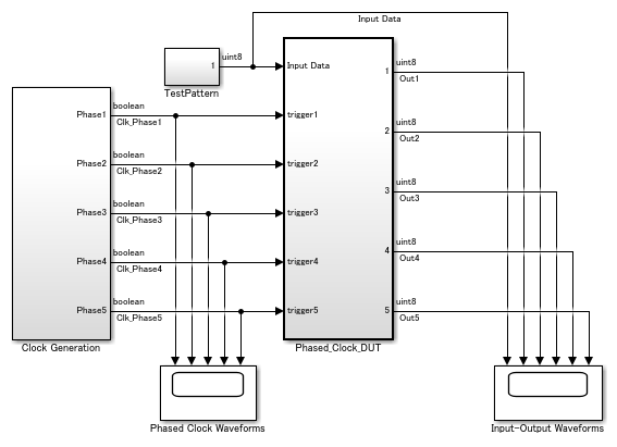
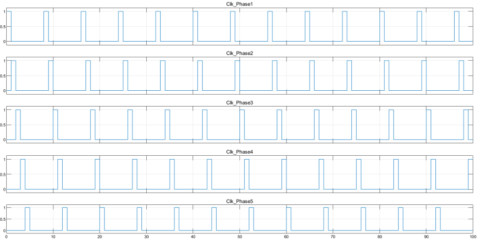
The model contains the Clock Generation subsystem which outputs five clock signals that run at same rate, but are out of phase. Run the simulation for the model and view waveforms of the phased clocks.
These clock signals are connected to trigger port of the triggered subsystems placed in the Phased_Clock_DUT subsystem. Open Phased_Clock_DUT subsystem.
open_system("PhasedClocksUsingTriggeredSubsystem/Phased_Clock_DUT");
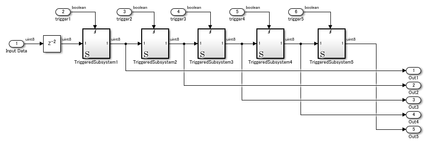
Enable Use trigger signal as clock option and generate HDL code for Phased_Clock_DUT subsystem. In the generated code, trigger port of the triggered subsystem acts as a clock which is driven by the corresponding clock signal.
Generate Multiple Clocks and Resets Using Triggered and Resettable Subsystems
This example shows how to model multiple clock and reset signals using triggered and resettable subsystems. Using trigger as clock functionality, you can model multiple clock signals from multiple triggered subsystems. By placing the resettable subsystem inside each triggered subsystem, you can model multiple reset signals in your Simulink model.
The model AsynchronousClockandResetUsingTriggerAsClock has a DUT subsystem which contains a two Triggered Subsystem. Load and open the AsynchronousClockandResetUsingTriggerAsClock model by running these commands:
load_system("AsynchronousClockandResetUsingTriggerAsClock"); set_param("AsynchronousClockandResetUsingTriggerAsClock",'SimulationCommand','Update') open_system("AsynchronousClockandResetUsingTriggerAsClock/DUT");
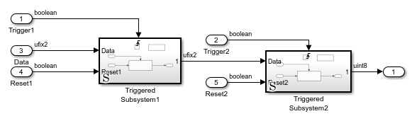
A resettable subsystem is placed within the triggered subsystem. Using resettable subsystem, you can model a reset port for your model. Minimize the global reset option so that model has reset ports from resettable subsystems. To minimize global reset option, enable Minimize global resets in the HDL Code Generation > Global Settings > Ports tab of the configuration settings.
To use trigger signal as clock in your generated HDL code, enable Use trigger signal as clock option in the HDL Code Generation > Global Settings > Ports tab of the configuration settings. Then, generate the HDL code for a DUT subsystem using makehdl command or HDL Coder™ app:
makehdl("AsynchronousClockandResetUsingTriggerAsClock/DUT")
The generated code for a DUT subsystem is shown in code snippet below. HDL Coder generates two trigger ports for the DUT subsystem which are used as clock signal in the triggered subsystems and two reset ports from the resettable subsystems.
 ENTITY DUT IS
   PORT( Trigger1                          :   IN    std_logic;
         Trigger2                          :   IN    std_logic;
         Data                              :   IN    std_logic_vector(1 DOWNTO 0);  -- ufix2
         Reset1                            :   IN    std_logic;
         Reset2                            :   IN    std_logic;
         Out2                              :   OUT   std_logic_vector(7 DOWNTO 0)  -- uint8
         );
 END DUT;

 BEGIN
     u_Triggered_Subsystem1 : Triggered_Subsystem1
       PORT MAP( Trigger => Trigger1,
                 Data => Data,  -- ufix2
                 Reset1 => Reset1,
                 Out1 => Triggered_Subsystem1_out1  -- ufix2
                 );

     u_Triggered_Subsystem2 : Triggered_Subsystem2
       PORT MAP( Trigger => Trigger2,
                 Data => Triggered_Subsystem1_out1,  -- ufix2
                 Reset2 => Reset2,
                 Out1 => Triggered_Subsystem2_out1  -- uint8
                 );

     Out2 <= Triggered_Subsystem2_out1;
Model Asynchronous and Synchronous Reset for a Simulink Model
You can generate synchronous and asynchronous external resets for your Simulink model by using nested triggered and resettable subsystems. You can use trigger-as-clock functionality to model the trigger port from a Triggered Subsystem as a clock and use Resettable Subsystem to model external reset port.
| Simulink Model | Model Parameters | Type of External Reset | Generated HDL Code |
|---|---|---|---|
| Resettable subsystem is placed inside the triggered subsystem | Use trigger signal as clock:on | Synchronous | always @(posedge Trigger) begin : Delay_process if (Reset_1 == 1'b1) begin Delay_out1 <= 2'b00; end ...In this generated HDL code,Reset_1 is a synchronous reset. |
| Triggered subsystem is placed inside the resettable subsystem | Use trigger signal as clock:on | Asynchronous | always @(posedge Trigger or posedge Reset_1) begin : Delay_process if (Reset_1 == 1'b1) begin Delay_out1 <= 2'b00; end ...In this generated HDL code,Reset_1 is an asynchronous reset. |
| Model the subsystem hierarchy as Resettable Subsystem > Triggered Subsystem > Resettable Subsystem | Use trigger signal as clock:on | Both synchronous and asynchronous | always @(posedge Trigger or posedge reset) begin : Delay_process if (reset == 1'b1) begin Delay_out1 <= 2'b00; end else begin if (Reset_1 == 1'b1) begin Delay_out1 <= 2'b00; end ... In this generated HDL code,reset is an asynchronous reset andReset_1 is a synchronous reset. |
See Also
Using Triggered Subsystems for HDL Code Generation