Variant Connector - Remove or disconnect physical components from network - MATLAB (original) (raw)
Remove or disconnect physical components from network
Since R2020b
Libraries:
Simscape / Utilities
Description
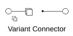
The Variant Connector block lets you define variant choices in a physical network. Variant choices allow you to exclude some components from simulation without physically removing the components from the physical network. The components to be disconnected must be connected to the port associated with condition data. During simulation, the variant condition is propagated to all the connected components within the physical network. If the variant control associated with the block evaluates totrue, all the components that are connected to the block become active. If the variant control evaluates to false, all the components connected to the block become inactive.
Examples
Limitations
- The Variant Connector block does not propagate the variant condition across the boundary between the Simscape™ physical network and the Simulink® blocks connected to it. In other words, if a block has both conserving ports and Simulink signal ports, such as a Simulink-PS Converter, a PS-Simulink Converter block, or a Subsystem block, the Variant Connector block stops propagating the variant condition at the boundary of that block. The condition is not propagated to any of its connected blocks. For more information, see Variant Condition Propagation From Variant Connector Block to Subsystem Block.
Ports
Conserving
This port is located on the left side of the block and is labeled with a rectangle. During simulation, if the variant choice associated with the block evaluates to true, all the components that are connected to this port become active. If the variant choice associated with the block evaluates tofalse, all the components connected to this port become inactive.
By default, this port is untyped. You define the type of this port by connecting it to a conserving port of another block, components in the network, or a Simscape Bus port.
Conserving connection port. By default, this port is untyped.
You define the type of the port by connecting it to a conserving port of another block, components in the network, or a Simscape Bus port.
Parameters
Select a connector type based on the components to deactivate.
Leaf: If you want to deactivate all the components connected to the block, set Connector Type toLeaf.
For example, in this model, the variant condition associated with the Variant Connector block, ConneBlk1, isA == 1. The variant condition associated with the Variant Connector block, ConneBlk2, isB == 1. During simulation, whenA == 1evaluates totrueandB == 1evaluates tofalse, all the components connected to ConneBlk1 block become active, and all the components connected to ConneBlk2 block become inactive.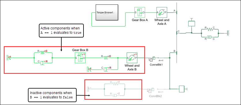
Primary and Nonprimary: If you want to restrict the propagation of the variant condition to a set of components, create a Bounded region by using primary and nonprimary connector blocks. To form a bounded region, the primary and nonprimary connector blocks must have the same Connector Tag property.
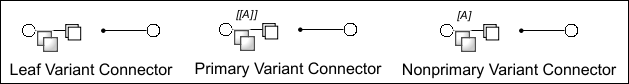
When you set Connector Type toPrimaryorNonprimary, the connector tag of the block is displayed on the block icon. The connector tag of the primary connector block is displayed with double lines and the connector tag of the nonprimary connector block is displayed with single lines.
A primary Variant Connector block and all nonprimaryVariant Connector blocks with the same Connector Tag as the primary block constitute a set of related blocks.
You can select a primary or nonprimary Variant Connector block to highlight all related Variant Connector blocks.
The blocks that are highlighted in the model canvas are also highlighted in the miniature map.
To show a related block in an open diagram, pause on the ellipsis that appears after selection. Then, select Related Blocks from the action bar. When multiple blocks correspond to the selected block, a list of related blocks opens. You can filter the list of related blocks by entering a search term in the text box. After you select a related block from the list, window focus goes to the open diagram or new tab that shows the related block.
Specify an identifier in the Connector Tag parameter. The primary and nonprimary connector blocks with the same tag form a Bounded region.
Dependencies
To enable this parameter, set Connector Type toPrimary or Nonprimary.
Displays the variant controls available in the global workspace. The variant control can be a Boolean condition expression containing a regular MATLAB variable or a [Simulink.VariantExpression](../../simulink/slref/simulink.variantexpression-class.html) object representing a Boolean condition expression.
To edit a variant name, double-click a Variant control expression cell and type in the variant control expression. ClickApply after you edit a variant control name.
When the variant control associated with the block evaluates totrue, all the components connected to the block become active.
Programmatic Use
| Block Parameter: VariantControls |
|---|
| Type: cell array of character vectors |
| Value: Variant control that is associated with the Variant choice |
| Default: 'Variant' |
This read-only field is based on the condition for the associated Variant control in the global workspace. Create or change a Variant condition in theSimulink.VariantExpression parameter dialog box or in the global workspace.
For more information, Simulink.VariantExpression.
Select Show variant condition on block to display the variant condition associated with the block on the block icon.
Click Open block in Variant Manager to open the Variant Manager.
More About
A bounded region is a part of a model located between one Variant Connector block whereConnector type is set to Primary and any number of Variant Connector blocks where Connector type is set toNonprimary. All of the blocks in a bounded region must use the same Connector tag parameter.
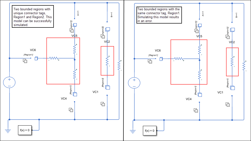
For example, this model has two bounded regions. The first region has one primary and two nonprimary Variant Connector blocks. These blocks are connected to each other by the connector tag Region1 and the associated variant condition A == 1. The second region has one primary and one nonprimary Variant Connector block. These blocks are connected to each other by the connector tag Region2 and the associated variant condition B == 1. During simulation, whenA == 1 evaluates to true, the components in the first region become active. When B == 1 evaluates tofalse, the components in the second region become inactive.

When you create a bounded region, ensure that:
- Each region has only one primary Variant Connector block. Each primary Variant Connector block is connected to at least one nonprimary Variant Connector block. All Variant Connector blocks must be connected using the port associated with condition information.
- All the primary and nonprimary blocks are at the same level of model hierarchy.
- Each region has a unique connector tag in a model hierarchy.
- The region is bounded and has no external connections.
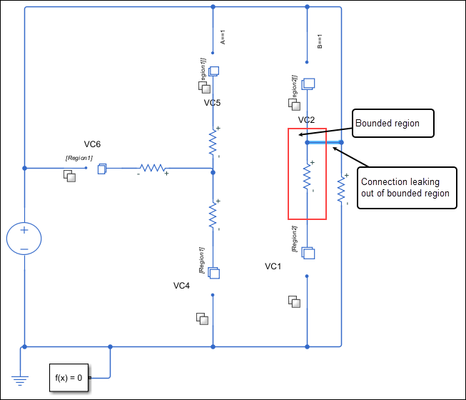
- There are no Variant Connector blocks where the Condition type is set to
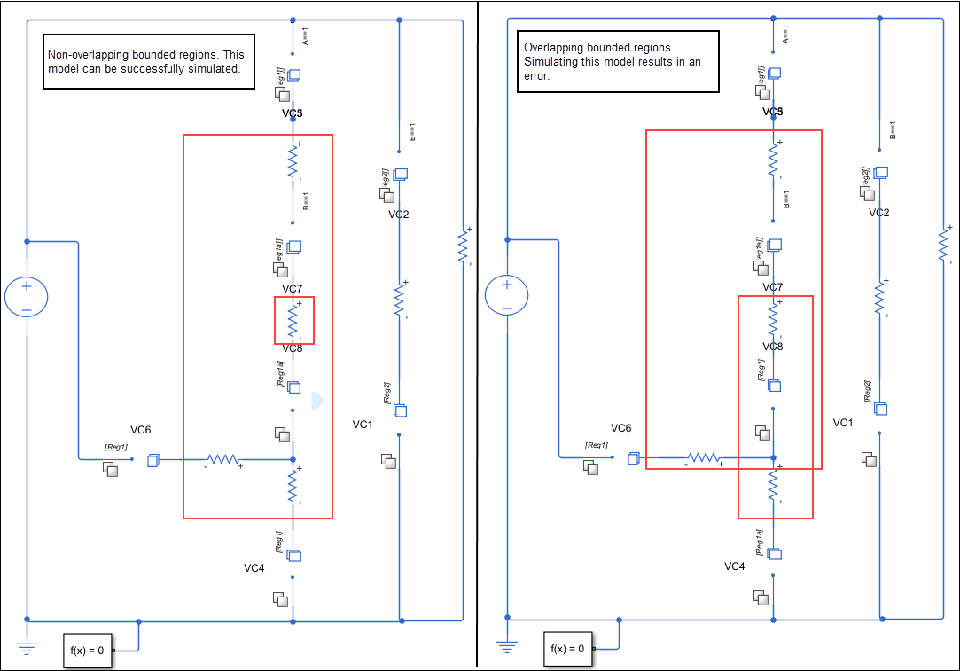
Leafinside the bounded region. - No bounded regions overlap each other.
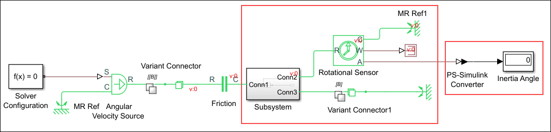
The Variant Connector block does not propagate the variant condition across the boundary between the Simscape physical network and the Simulink blocks connected to it. In other words, if a block has both conserving ports and Simulink signal ports, such as a Simulink-PS Converter, a PS-Simulink Converter block, or a Subsystem block, the Variant Connector block stops propagating the variant condition at the boundary of that block. The condition is not propagated to any of its connected blocks.
For example, in this model, as the Subsystem block has both conserving ports and Simulink signal ports, the Variant Connector block does not propagate the variant condition to the Subsystem block.

However, if the Subsystem has only conserving ports, theVariant Connector block propagates the variant condition to the Subsystem block and to the blocks that are connected to theSubsystem block. However, the propagation stops at thePS-Simulink Converter block because it has both conserving ports and Simulink signal ports.
Extended Capabilities
Usage notes and limitations:
The code is generated only for active blocks in the model. Inactive blocks do not participate in code generation.
Version History
Introduced in R2020b