Create Flow Charts by Using Pattern Wizard - MATLAB & Simulink (original) (raw)
The Pattern Wizard is a utility that generates common flow chart patterns for use in graphical functions and charts. The Pattern Wizard offers several advantages over manually creating flow charts. The Pattern Wizard:
- Generates common logic and iterative loop patterns.
- Promotes consistency in geometry and layout across patterns.
- Facilitates storing and reusing patterns from a central location.
- Allows inserting patterns in an existing flow chart.
The Pattern Wizard generates flow charts whose geometry and layout comply with the guidelines from the MathWorks Advisory Board (MAB). You can customize your flow chart by modifying the conditions and actions or by inserting additional logic patterns. You can also save your flow chart as a custom pattern in the Pattern Wizard for later reuse.
For example, suppose that you want to use the Pattern Wizard to create a graphical function for iterating over the upper triangle of a two-dimensional matrix. The function consists of two nested for loops in which the row index i is always less than or equal to the column index_j_. By using the Pattern Wizard, you can:
- Create a flow chart for the outer loop that iterates over the row index_
i_. See Create Reusable Flow Charts. - Extend the flow chart by inserting an inner loop that iterates over the column index
j. See Insert Logic Patterns in Existing Flow Charts. - Save the flow chart as a custom pattern in the Pattern Wizard. See Save Custom Flow Chart Patterns.
- Reuse the custom pattern in a graphical function. See Reuse Custom Flow Chart Patterns.
Create Reusable Flow Charts
To create a flow chart, on the Modeling tab, select a pattern from the gallery. Pattern selections include:
- , , , and other nested decision patterns.
- , , and loop patterns.
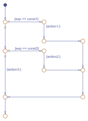
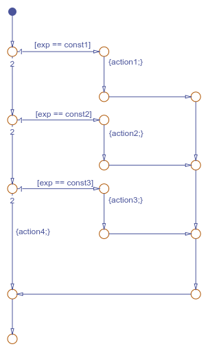
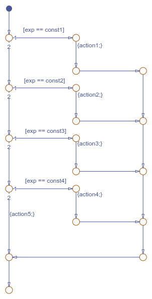
- Switch patterns with up to four cases.
- Custom patterns that you saved for later reuse.
- Patterns that you define in a MATLAB®
.mfile.
The Pattern dialog box prompts you for conditions and actions specific to the pattern that you select. For more information on flow chart patterns, see MAB-Compliant Patterns from the Pattern Wizard.
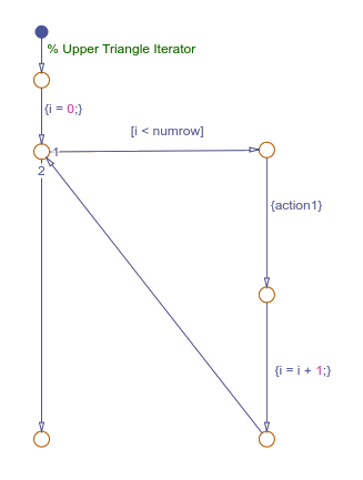
For example, to create the outer for loop in the upper triangle iterator pattern:
- On the Modeling tab, select > .
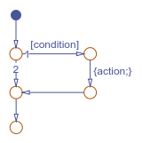
- In the Pattern dialog box, specify the initializer, loop test, and counting expressions for iterating through the first dimension of the matrix:
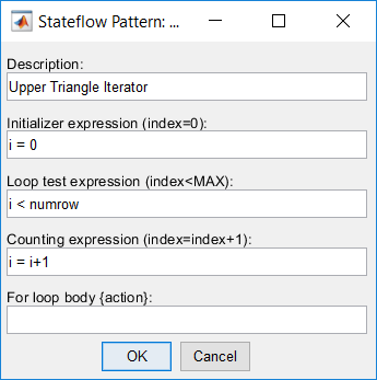
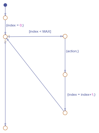
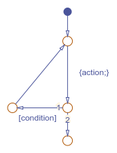
- Click OK. The Pattern Wizard generates this flow chart.
To complete the upper triangle iterator pattern, insert a secondfor loop along the vertical transition in this flow chart.
Insert Logic Patterns in Existing Flow Charts
Use the Pattern Wizard to add loop or decision logic extensions to an existing flow chart. Select an eligible vertical transition and choose a pattern from the gallery. Options include decision, loop, and switch patterns. The Pattern dialog box prompts you for conditions and actions specific to the pattern that you select.
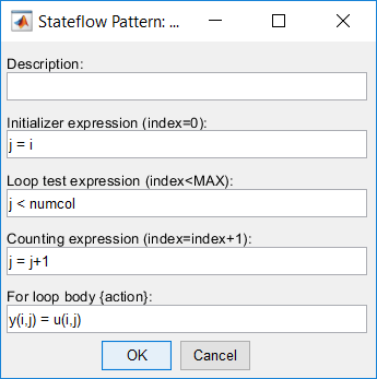
For example, to add the second loop in the upper triangle iterator pattern:
- In the Stateflow® Editor, from the outer
forloop pattern, select the vertical transition labeled{action1}. - On the Modeling tab, select > .
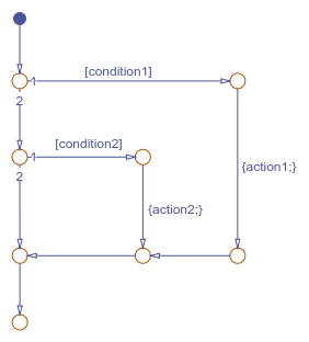
- In the Pattern dialog box, specify the initializer, loop test, and counting expressions for iterating through the second dimension of the matrix. The initializer expression ensures that i never exceeds_j_. Also enter an action that retrieves each element in the upper triangle of the matrix.
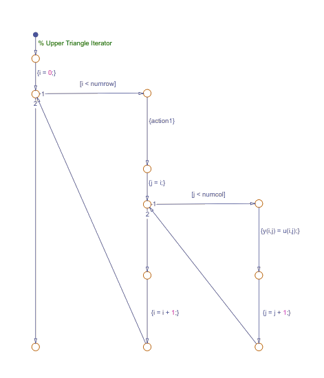
- Click OK. The Pattern Wizard adds the second loop to the flow chart.
- Save the model containing the pattern.
Guidelines for Inserting Logic Patterns
When you create logic extensions:
- You can select only one transition to extend at a time. The selected transition must be exactly vertical and have a destination junction.
- You can extend only flow charts created by the Pattern Wizard.
- The Stateflow chart containing the flow chart can contain only junctions and transitions. The chart cannot contain other objects, such as states, functions, or truth tables.
- You cannot extend a pattern that has been custom-created or modified.
- You cannot choose a custom pattern as the extension.
If your selection is not eligible for insertion, when you choose a pattern from the gallery, you see a message instead of pattern options.
| Message | Issue |
|---|---|
| Select a vertical transition | You have not selected a vertical transition. |
| Selected transition must be exactly vertical | You selected a transition, but it is not vertical. |
| Select only one vertical transition | You have selected more than one transition. |
| Editor must contain only transitions and junctions | There are other objects, such as states, functions, or truth tables, in the chart. |
Save Custom Flow Chart Patterns
Use the Pattern Wizard to save flow chart patterns in a central location, and then easily retrieve them for reuse in graphical functions and charts. Select the flow chart with the pattern that you want to save and select Pattern >Save As Pattern.
For example, suppose that you want to save the upper triangle iterator pattern for later reuse:
- Create a folder for storing your custom patterns. See Guidelines for Creating a Custom Pattern Folder.
- In the Stateflow Editor, select the upper triangle iterator flow chart.
- On the Modeling tab, selectPattern > Save As Pattern.
- If you have not designated the custom pattern folder, the Pattern Wizard prompts you to select a folder. Choose the folder that you created and clickSelect Folder.
- At the prompt, name your pattern
UpperTriangleIteratorand click Save. The Pattern Wizard saves your pattern as a model fileUpperTriangleIterator.slxin the custom pattern folder.
Guidelines for Creating a Custom Pattern Folder
The Pattern Wizard uses a single, flat folder for saving and retrieving flow chart patterns.
- Store all flow charts at the top level of the custom pattern folder. Do not create subfolders.
- Make sure that all flow chart files have an
.mdlor.slxextension.
Change Your Custom Pattern Folder
The Pattern Wizard remembers your choice of custom pattern folder for future sessions. To choose a different folder, use the sfpref function. For example, to set the custom pattern folder toC:\patterns, enter:
sfpref(PatternWizardCustomDir=fullfile("C:","patterns"));
Alternatively, rename your existing custom pattern folder and do one of the following:
- Save a new custom pattern to the Pattern Wizard.
- Reuse an existing custom pattern from the Pattern Wizard.
The Pattern Wizard prompts you to choose a new folder.
Reuse Custom Flow Chart Patterns
The Pattern Wizard stores your flow charts as model files in the custom pattern folder. The patterns that you save in this folder appear in a drop-down list when you select Pattern > Custom. You can add a custom pattern directly to a chart or to a subcharted graphical function in your chart.
For example, to add the upper triangle iterator custom pattern to a graphical function:
- From the object palette, add a graphical function to your chart as described in Define a Graphical Function.
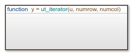
- Enter this function signature:
function y = ut_iterator(u, numrow, numcol)
The function takes three inputs.Input Description u 2-D matrix numrow Number of rows in the matrix numcol Number of columns in the matrix - Right-click inside the function and select > . The function appears as an opaque box.
- Double-click the subcharted function to open it.
- Remove the default flow chart from the graphical function.
- On the Modeling tab, selectPattern > Custom. A dialog box opens, listing all the patterns that you have saved in your custom pattern folder.
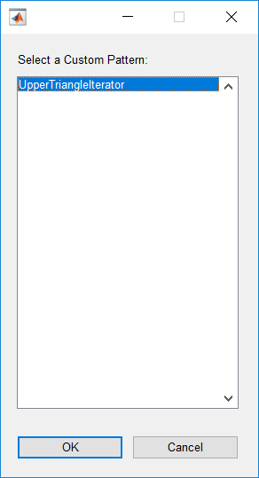
- Select the upper triangle iterator pattern and clickOK. The Pattern Wizard adds your custom pattern to the graphical function.
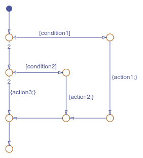
- In the graphical function, in place of
action1, substitute an appropriate action. This action repeats once for every row of the matrix.
MAB-Compliant Patterns from the Pattern Wizard
The Pattern Wizard generates flow charts whose geometry and layout comply with the guidelines from the MathWorks Advisory Board (MAB).
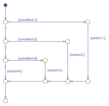
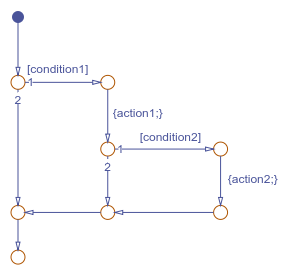
Decision Patterns

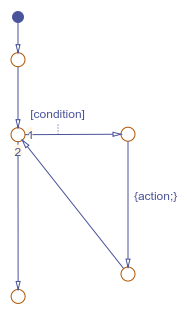
Loop Patterns
Switch Patterns