Adapter - Connect components with different interfaces - Simulink (original) (raw)
Connect components with different interfaces
Description
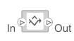
The Adapter block allows you to connect the source and destination ports of components that have different interface definitions.
To add or connect System Composer™ components:
- Add an Adapter block from the Modeling tab or the palette. The Adapter block has
InandOutports. - Click and drag a port to create a connection. Connect each port to another component. You can also create a new component to complete the connection.
- Insert an Adapter block between two ports with different interfaces. You can create mappings between interface elements on each port.
To map between interfaces, apply interface conversions, and enter bus creation mode for architecture models:
- Double-click the Adapter block to open the Interface Adapter dialog. In the dialog box, you can create and edit mappings between input and output interfaces, and set the Apply Interface conversion parameter to
UnitDelayto break an algebraic loop orRateTransitionto reconcile different sample time rates for reference models. When output interfaces are undefined, you can use input interfaces in bus creation mode to author owned output interfaces.
When you have Simulink® component behaviors with signal or message lines, then to merge message connections for architecture models and signal or message connections for software architecture models:
- Manually configure the Adapter block by double-clicking the block to open the Interface Adapter. Set theApply Interface conversion parameter to
Merge. - For software architecture models, from the toolstrip, add a Merge block, which is a preconfigured Adapter block for merging.
Examples
Limitations
- When used for structural interface adaptations, the Adapter block uses bus element ports internally and, subsequently, only supports virtual buses.
- The Adapter block does not support mixing messages and signals as inputs and outputs.
- When used in AUTOSAR architecture models, the names of corresponding input and output interface elements must match.
Ports
Input
If you connect to a source component, the interfaces on the ports should be compatible.
Output
If you connect to a destination component, the interfaces on the ports should be compatible.
More About
| Term | Definition | Application | More Information |
|---|---|---|---|
| Data dictionary | A data dictionary is a repository of data relevant to your model. The Architectural Data section of a data dictionary stores shared definitions used in Simulink and architecture model interfaces, such as port interfaces, data types, and system wide constants. For more information, see What Is a Data Dictionary? | You can save local interfaces on a System Composer model to the Architectural Data section of a Simulink data dictionary using the Interface Editor. In addition to the Interface Editor, you can also use the Architectural Data Editor to manage and modify interfaces and value types. | Manage Interfaces with Data DictionariesReference Data DictionariesStore Shared Data in Architectural Data Section |
| Data interface | A data interface defines the kind of information that flows through a port. The same interface can be assigned to multiple ports. A data interface can be composite, meaning that it can include data elements that describe the properties of an interface signal. | Data interfaces represent the information that is shared through a connector and enters or exits a component through a port. Use the Interface Editor to create and manage data interfaces and data elements and store them in a data dictionary for reuse between models. | Create Architecture Model with Interfaces and Requirement LinksDefine Port Interfaces Between Components |
| Data element | A data element describes a portion of an interface, such as a communication message, a calculated or measured parameter, or other decomposition of that interface. | Data interfaces are decomposed into data elements that can represent pins or wires in a connector or harness, messages transmitted across a bus, and data structures shared between components. | Create InterfacesAssign Interfaces to Ports |
| Value type | A value type can be used as a port interface to define the atomic piece of data that flows through that port and has a top-level type, dimension, unit, complexity, minimum, maximum, and description. | You can also assign the type of data elements in data interfaces to value types. Add value types to data dictionaries using the Interface Editor so that you can reuse the value types as interfaces or data elements. | Create Value Types as Interfaces |
| Owned interface | An owned interface is an interface that is local to a specific port and not shared in a data dictionary or the model dictionary. | Create an owned interface to represent a value type or data interface that is local to a port. | Define Owned Interfaces Local to Ports |
| Adapter | An adapter connects two components with incompatible port interfaces by mapping between the two interfaces. An adapter can act as a unit delay, rate transition, or merge. You can also use an adapter for bus creation. Use the Adapter block to implement an adapter. | With an adapter, on the Interface Adapter dialog box, you can: create and edit mappings between input and output interfaces, apply an interface conversionUnitDelay to break an algebraic loop, apply an interface conversionRateTransition to reconcile different sample time rates for reference models, apply an interface conversion Merge to merge two or more message or signal lines, and when output interfaces are undefined, you can use input interfaces in bus creation mode to author owned output interfaces. | Interface AdapterAdapter |
Version History
Introduced in R2019a