Reference Component - Link to architectural definition or Simulink behavior - Simulink (original) (raw)
Link to architectural definition or Simulink behavior
Description
Use a Reference Component block to link an architectural definition of a System Composer™ component, an architectural definition of an AUTOSAR component, or a Simulink® behavior.
Add ports to the block to connect to other components. Define an interface for the ports, add properties associated with the component using stereotypes, and define parameters.
To add or connect System Composer components:
- Add a Reference Component block from theModeling tab or the palette. You can also click and drag a box on the canvas, then select the Reference Component block.
Tip
You can drag to add a reference component linked to a model or subsystem into a System Composer model. Drag a model or subsystem file from the file explorer to add a reference component to the architecture model canvas.
For example, dragging a model SLX file into the architecture model canvas adds aReference Component block that references the model in the SLX file.
Files that you drag to add must be on the MATLAB® path. Creating reference components by dragging files from the MATLAB Editor into the model canvas is not supported. - Attach a referenced model by double-clicking the Reference Component block to open the Block Parameters dialog box.
- Add and edit ports on a Reference Component block. Click the edge of the block to add a port, then use the Property Inspector to rename the port.
- To import your shared data dictionary from your System Composer architecture model, in the Model Explorer for your referenced model, under , on the tab, click . Use the Interface Editor to assign interfaces to the ports of your referenced model and edit interface definitions.
- Click and drag any port to create a connection. Connect to another component. You can also create a new component to complete the connection.
- To connect Reference Component blocks to architecture or composition model root ports, drag from the component ports to the containing model boundary. When you release the connection, a root port is created at the boundary.
Note
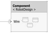
You can add a mask icon to your component to illustrate the system represented by your component. For more information, see Add Mask Icon on Component.
To manage Reference Component block contents:
- When you create a Reference Component block, you have the option to right-click the component and select
Block Parameters. From here, you can specify your reference model or subsystem name, if it already exists. The reference model or subsystem can be a System Composer architecture, AUTOSAR architecture, or a Simulink model or subsystem. - To add or remove stereotypes from Reference Component blocks, first import the profile into the referenced model or subsystem using the Profile Editor. If you apply multiple stereotypes to the reference component, to change the stereotype order, see Change Stereotype Order Using Manage Profiles Tool.
- To break the reference link for a Reference Component block, you have the option to right-click and select , which removes the contents of the architecture model referenced by the specified component and breaks the link to the reference model. The Reference Component block becomes a regular Component block.
With a regular Component block, you can right-click the block and convert it to a reference component.
- To save the contents of the component as an architecture model or subsystem that can be referenced in multiple places and kept in sync, select > . The component becomes a reference component that links to the referenced architecture model or subsystem.
Note
To type ports on architecture subsystems with interfaces, you must link an external interface data dictionary. Architecture subsystems do not contain a model workspace. For more information, see Manage Interfaces with Data Dictionaries. - To save the contents of the component as a software architecture model, select > .
Create Architectureand then selectSoftware Architecture. For more information, see Export Architecture to Software Architecture. - To save the contents of the component as an AUTOSAR architecture model, select > . For more information, see Create AUTOSAR Architecture from Component.
- To create a new Simulink reference model or subsystem and link to it, select > . For more information, see Implement Component Behavior Using Simulink.
- To link to a known model or subsystem, which can be a System Composer architecture model, a Simulink model, or an AUTOSAR architecture model, select .
Note
Components with physical ports cannot be saved as architecture models, model references, software architectures, or Stateflow® chart behaviors. Components with physical ports can only be saved as subsystem references or as subsystem component behaviors.
Examples
Ports
Input
If you connect to a source component, the interfaces on the ports are shared.
Output
If you connect to a destination component, the interfaces on the ports are shared.
Physical
If you connect to another component, the physical interfaces on the ports are shared.
More About
| Term | Definition | Application | More Information |
|---|---|---|---|
| Architecture | A System Composer architecture represents a system of components and how they interface with each other structurally and behaviorally. | Different types of architectures describe different aspects of systems. You can use views to visualize a subset of components in an architecture. You can define parameters on the architecture level using the Parameter Editor. | Compose Architectures VisuallyAuthor Parameters in System Composer Using Parameter Editor |
| Root | A root is at the top of an architecture hierarchy. A root architecture has a boundary defined by its architecture ports that surround the system of interest. | The root architecture has a system boundary surrounding your architecture model. You can add architecture ports that define interfaces across the boundary. | Compose Architectures Visually |
| Model | A System Composer model is the file that contains architectural information, such as components, ports, connectors, interfaces, and behaviors. | Perform operations on a model including extracting root-level architecture, applying profiles, linking interface data dictionaries, or generating instances from model architecture. A System Composer model is stored as an SLX file. | Create Architecture Model with Interfaces and Requirement Links |
| Component | A component is a replaceable part of a system that fulfills a clear function in the context of an architecture. A component defines an architectural element, such as a function, another system, hardware, software, or other conceptual entity. A component can also be a subsystem or subfunction. | Represented as a block, a component is a part of an architecture model that can be separated into reusable artifacts. Transfer information between components with port interfaces using the Interface Editor, and parameters using the Parameter Editor. | Compose Architectures Visually |
| Port | A port is a node on a component or architecture that represents a point of interaction with its environment. A port permits the flow of information to and from other components or systems. | Component ports are interaction points on the component to other components. Architecture ports are ports on the boundary of the system, whether the boundary is within a component or the overall architecture model. The root architecture has a boundary defined by its ports. | Compose Architectures Visually |
| Connector | Connectors are lines that provide connections between ports. Connectors describe how information flows between components or architectures. | A connector allows two components to interact without defining the nature of the interaction. Set an interface on a port to define how the components interact. | Compose Architectures Visually |
| Term | Definition | Application | More Information |
|---|---|---|---|
| Physical subsystem | A physical subsystem is a Simulink subsystem with Simscape™ connections. | A physical subsystem with Simscape connections uses a physical network approach suited for simulating systems with real physical components and represents a mathematical model. | Implement Component Behavior Using Simscape |
| Physical port | A physical port represents a Simscape physical modeling connector port called a Connection Port (Simscape). | Use physical ports to connect components in an architecture model or to enable physical systems in a Simulink subsystem. | Define Physical Ports on Component |
| Physical connector | A physical connector can represent a nondirectional conserving connection of a specific physical domain. Connectors can also represent physical signals. | Use physical connectors to connect physical components that represent features of a system to simulate mathematically. | Architecture Model with Simscape Behavior for a DC Motor |
| Physical interface | A physical interface defines the kind of information that flows through a physical port. The same interface can be assigned to multiple ports. A physical interface is a composite interface equivalent to a Simulink.ConnectionBus object that specifies a number of Simulink.ConnectionElement objects. | Use a physical interface to bundle physical elements to describe a physical model using at least one physical domain. | Specify Physical Interfaces on Ports |
| Physical element | A physical element describes the decomposition of a physical interface. A physical element is equivalent to a Simulink.ConnectionElement object. | Define the Type of a physical element as a physical domain to enable use of that domain in a physical model. | Describe Component Behavior Using Simscape |
Version History
Introduced in R2019a
See Also
Functions
- addComponent | addPort | connect | inlineComponent | createSimulinkBehavior | createArchitectureModel | createStateflowChartBehavior | extractArchitectureFromSimulink | linkToModel | isReference