systemcomposer.arch.Component - System Composer component - MATLAB (original) (raw)
System Composer component
Description
Creation
Create a component in an architecture model using the addComponent function.
model = systemcomposer.createModel('archModel'); arch = get(model,'Architecture'); component = addComponent(arch,'newComponent');
Properties
Name of component, specified as a character vector.
Example: 'newComponent'
Data Types: char
Architecture that defines component structure, specified as a systemcomposer.arch.Architecture object. For a component that references a different architecture model or subsystem, this property returns a handle to the root architecture of that model or subsystem.
Architecture that component owns, specified as a systemcomposer.arch.Architecture object. For components that reference an architecture model, this property is empty. For components that reference an architecture subsystem, this property is the owned architecture of the component.
Position of component on canvas, specified as a vector of coordinates, in pixels[left top right bottom].
Name of model that component references if linked component, specified as a character vector.
Data Types: char
Whether component is Adapter block, specified as 1 (true) or 0 (false).
Data Types: logical
Simulink® handle, specified as a double.
This property is necessary for several Simulink related workflows and for using Requirements Toolbox™ programmatic interfaces.
Example: handle = get(object,'SimulinkHandle')
Data Types: double
Simulink handle to parent System Composer model, specified as a double.
This property is necessary for several Simulink related workflows and for using Requirements Toolbox programmatic interfaces.
Example: handle = get(object,'SimulinkModelHandle')
Data Types: double
Unique external identifier, specified as a character vector. The external ID is preserved over the lifespan of the element and through all operations that preserve the UUID.
Data Types: char
Universal unique identifier, specified as a character vector.
Example: '91d5de2c-b14c-4c76-a5d6-5dd0037c52df'
Data Types: char
Object Functions
Examples
Build an architecture model programmatically using System Composer™.
To build a model, add a data dictionary with data interfaces, data elements, a value type, and a physical interface, then add components, ports, and connections. Create a profile with stereotypes and properties and then apply those stereotypes to model elements. Assign an owned interface to a port. After the model is built, you can create custom views to focus on specific considerations. You can also query the model to collect different model elements according to criteria you specify.
Add Components, Ports, Connections, and Interfaces
Create a model and extract its architecture.
model = systemcomposer.createModel("mobileRobotAPI"); arch = model.Architecture;
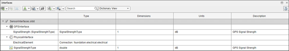
Create a data dictionary and add a data interface. Add a data element to the data interface. Add a value type to the data dictionary. Assign the type of the data element to the value type. Add a physical interface and physical element with a physical domain type. Link the data dictionary to the model.
dictionary = systemcomposer.createDictionary("SensorInterfaces.sldd"); interface = dictionary.addInterface("GPSInterface"); element = interface.addElement("SignalStrength"); valueType = dictionary.addValueType("SignalStrengthType",Units="dB", ... Description="GPS Signal Strength"); element.setType(valueType); physicalInterface = dictionary.addPhysicalInterface("PhysicalInterface"); physicalElement = addElement(physicalInterface,"ElectricalElement", ... Type="electrical.electrical"); linkDictionary(model,"SensorInterfaces.sldd");
Save the changes to the data dictionary.
Save the model.
Open the model.
systemcomposer.openModel("mobileRobotAPI");
View the interfaces in the Interface Editor.
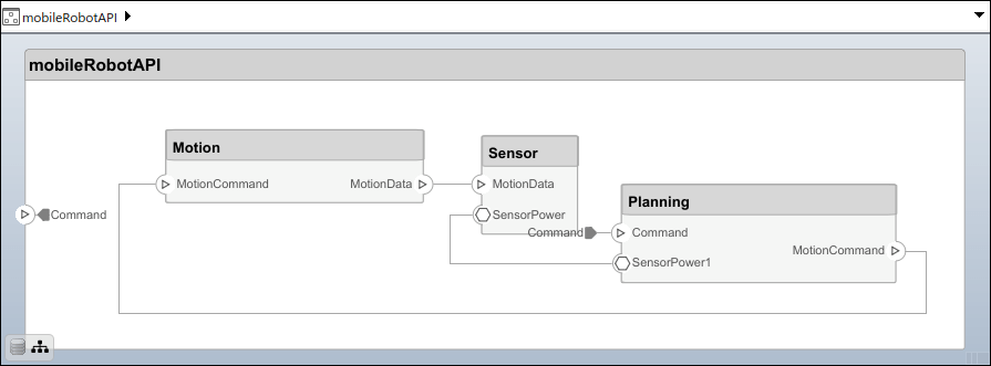
Add components, ports, and connections. Set the physical interface to the physical ports, which you connect later.
componentSensor = addComponent(arch,"Sensor"); sensorPorts = addPort(componentSensor.Architecture,{'MotionData','SensorPower'}, ... {'in','physical'}); sensorPorts(2).setInterface(physicalInterface)
componentPlanning = addComponent(arch,"Planning"); planningPorts = addPort(componentPlanning.Architecture, ... {'Command','SensorPower1','MotionCommand'}, ... {'in','physical','out'}); planningPorts(2).setInterface(physicalInterface)
componentMotion = addComponent(arch,"Motion"); motionPorts = addPort(componentMotion.Architecture,{'MotionCommand','MotionData'}, ... {'in','out'});
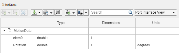
Create an owned interface on the MotionData port. Add an owned data element under the owned data interface. Assign the data element Rotation to a value type with units set to degrees.
ownedInterface = motionPorts(2).createInterface("DataInterface"); ownedElement = ownedInterface.addElement("Rotation"); subInterface = ownedElement.createOwnedType(Units="degrees");
View the interfaces in the Interface Editor. Select the MotionData port on the Motion component. In the Interface Editor, switch from Dictionary View to Port Interface View.
Connect components with an interface rule and the default name rule. The interface rule connects ports on components that share the same interface. By default, the name rule connects ports on components that share the same name.
c_sensorData = connect(arch,componentSensor,componentPlanning,Rule="interface"); c_motionData = connect(arch,componentMotion,componentSensor); c_motionCommand = connect(arch,componentPlanning,componentMotion);
Add and Connect Architecture Port
Add an architecture port on the architecture.
archPort = addPort(arch,"Command","in");
The connect command requires a component port as an argument. Obtain the component port, then connect.
compPort = getPort(componentPlanning,"Command"); c_Command = connect(archPort,compPort);
Save the model.
Arrange the layout by pressıng Ctrl+Shift+A or using this command.
Simulink.BlockDiagram.arrangeSystem("mobileRobotAPI");
Create and Apply Profile with Stereotypes
Profiles are XML files that you can apply to any model. You can add stereotypes with properties to profiles and then populate the properties with specific values in the Profile Editor. Along with the built-in analysis capabilities of System Composer, stereotypes help you optimize your system for performance, cost, and reliability.
Create Profile and Add Stereotypes
Create a profile.
profile = systemcomposer.createProfile("GeneralProfile");
Create a stereotype that applies to all element types.
elemSType = addStereotype(profile,"projectElement");
Create stereotypes for different types of components. You select these types according to your design needs.
pCompSType = addStereotype(profile,"physicalComponent",AppliesTo="Component"); sCompSType = addStereotype(profile,"softwareComponent",AppliesTo="Component");
Create a stereotype for connections.
sConnSType = addStereotype(profile,"standardConn",AppliesTo="Connector");
Add Properties
Add properties to the stereotypes. You can use properties to capture metadata for model elements and analyze nonfunctional requirements. These properties are added to all elements to which the stereotype is applied, in any model that imports the profile.
addProperty(elemSType,'ID',Type="uint8"); addProperty(elemSType,'Description',Type="string"); addProperty(pCompSType,'Cost',Type="double",Units="USD"); addProperty(pCompSType,'Weight',Type="double",Units="g"); addProperty(sCompSType,'develCost',Type="double",Units="USD"); addProperty(sCompSType,'develTime',Type="double",Units="hour"); addProperty(sConnSType,'unitCost',Type="double"',Units="USD"); addProperty(sConnSType,'unitWeight',Type="double",Units="g"); addProperty(sConnSType,'length',Type="double",Units="m");
Save Profile
Apply Profile to Model
Apply the profile to the model.
applyProfile(model,"GeneralProfile");
Apply stereotypes to components. Some components are physical components, while others are software components.
applyStereotype(componentPlanning,"GeneralProfile.softwareComponent") applyStereotype(componentSensor,"GeneralProfile.physicalComponent") applyStereotype(componentMotion,"GeneralProfile.physicalComponent")
Apply the connector stereotype to all connections.
batchApplyStereotype(arch,'Connector',"GeneralProfile.standardConn");
Apply the general element stereotype to all connectors and ports.
batchApplyStereotype(arch,'Component',"GeneralProfile.projectElement"); batchApplyStereotype(arch,'Connector',"GeneralProfile.projectElement");
Set properties for each component.
setProperty(componentSensor,'GeneralProfile.projectElement.ID','001'); setProperty(componentSensor,'GeneralProfile.projectElement.Description', ... 'Central unit for all sensors'); setProperty(componentSensor,'GeneralProfile.physicalComponent.Cost','200'); setProperty(componentSensor,'GeneralProfile.physicalComponent.Weight','450'); setProperty(componentPlanning,'GeneralProfile.projectElement.ID','002'); setProperty(componentPlanning,'GeneralProfile.projectElement.Description', ... 'Planning computer'); setProperty(componentPlanning,'GeneralProfile.softwareComponent.develCost','20000'); setProperty(componentPlanning,'GeneralProfile.softwareComponent.develTime','300'); setProperty(componentMotion,'GeneralProfile.projectElement.ID','003'); setProperty(componentMotion,'GeneralProfile.projectElement.Description', ... 'Motor and motor controller'); setProperty(componentMotion,'GeneralProfile.physicalComponent.Cost','4500'); setProperty(componentMotion,'GeneralProfile.physicalComponent.Weight','2500');
Set the properties of connections to be identical.
connections = [c_sensorData c_motionData c_motionCommand c_Command]; for k = 1:length(connections) setProperty(connections(k),'GeneralProfile.standardConn.unitCost','0.2'); setProperty(connections(k),'GeneralProfile.standardConn.unitWeight','100'); setProperty(connections(k),'GeneralProfile.standardConn.length','0.3'); end
Add Hierarchy
Add two components named Controller and Scope inside the Motion component. Define the ports. Connect the components to the architecture and to each other, applying a connector stereotype. Hierarchy in an architecture diagram creates an additional level of detail that specifies how components behave internally.
motionArch = componentMotion.Architecture;
motionController = motionArch.addComponent('Controller'); controllerPorts = addPort(motionController.Architecture,{'controlIn','controlOut'}, ... {'in','out'}); controllerCompPortIn = motionController.getPort('controlIn'); controllerCompPortOut = motionController.getPort('controlOut');
motionScope = motionArch.addComponent('Scope'); scopePorts = addPort(motionScope.Architecture,{'scopeIn','scopeOut'},{'in','out'}); scopeCompPortIn = motionScope.getPort('scopeIn'); scopeCompPortOut = motionScope.getPort('scopeOut');
c_planningController = connect(motionPorts(1),controllerCompPortIn);
For output port connections, you can specify the destination data element.
c_planningScope = connect(scopeCompPortOut,motionPorts(2),DestinationElement="Rotation"); c_planningConnect = connect(controllerCompPortOut,scopeCompPortIn, ... "GeneralProfile.standardConn");
Save the model.
Arrange the layout by pressıng Ctrl+Shift+A or using this command.
Simulink.BlockDiagram.arrangeSystem("mobileRobotAPI/Motion");

Create Model Reference
Model references can help you organize large models hierarchically and define architectures or behaviors once that you can then reuse. When a component references another model, any existing ports on the component are removed, and ports that exist on the referenced model will appear on the component.
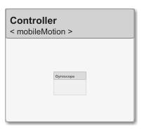
Create a new System Composer model. Convert the Controller component into a reference component to reference the new model. To add ports on the Controller component, you must update the referenced model mobileMotion.
referenceModel = systemcomposer.createModel("mobileMotion"); referenceArch = referenceModel.Architecture; newComponents = addComponent(referenceArch,"Gyroscope"); referenceModel.save
linkToModel(motionController,"mobileMotion");
Save the models.
referenceModel.save model.save
Make Variant Component
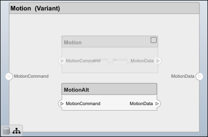
You can convert the Motion component to a variant component using the makeVariant function. The original component is embedded within a variant component as one of the available variant choices. You can design other variant choices within the variant component and toggle the active choice. Variant components allow you to choose behavioral designs programmatically in an architecture model to perform trade studies and analysis.
[variantComp,choice1] = makeVariant(componentMotion);
Add a variant choice named MotionAlt. The second argument defines the name, and the third argument defines the label. The label identifies the choice. The active choice is controlled by the label.
choice2 = addChoice(variantComp,{'MotionAlt'},{'MotionAlt'});
Create the necessary ports on MotionAlt.
motionAltPorts = addPort(choice2.Architecture,{'MotionCommand','MotionData'},{'in','out'});
Make MotionAlt the active variant.
setActiveChoice(variantComp,"MotionAlt")
Arrange the layout by pressıng Ctrl+Shift+A or using this command.
Simulink.BlockDiagram.arrangeSystem("mobileRobotAPI/Motion");
Save the model.
Clean Up
Run this script to remove generated artifacts before you run this example again.
More About
| Term | Definition | Application | More Information |
|---|---|---|---|
| Architecture | A System Composer architecture represents a system of components and how they interface with each other structurally and behaviorally. | Different types of architectures describe different aspects of systems. You can use views to visualize a subset of components in an architecture. You can define parameters on the architecture level using the Parameter Editor. | Compose Architectures VisuallyAuthor Parameters in System Composer Using Parameter Editor |
| Root | A root is at the top of an architecture hierarchy. A root architecture has a boundary defined by its architecture ports that surround the system of interest. | The root architecture has a system boundary surrounding your architecture model. You can add architecture ports that define interfaces across the boundary. | Compose Architectures Visually |
| Model | A System Composer model is the file that contains architectural information, such as components, ports, connectors, interfaces, and behaviors. | Perform operations on a model including extracting root-level architecture, applying profiles, linking interface data dictionaries, or generating instances from model architecture. A System Composer model is stored as an SLX file. | Create Architecture Model with Interfaces and Requirement Links |
| Component | A component is a replaceable part of a system that fulfills a clear function in the context of an architecture. A component defines an architectural element, such as a function, another system, hardware, software, or other conceptual entity. A component can also be a subsystem or subfunction. | Represented as a block, a component is a part of an architecture model that can be separated into reusable artifacts. Transfer information between components with port interfaces using the Interface Editor, and parameters using the Parameter Editor. | Compose Architectures Visually |
| Port | A port is a node on a component or architecture that represents a point of interaction with its environment. A port permits the flow of information to and from other components or systems. | Component ports are interaction points on the component to other components. Architecture ports are ports on the boundary of the system, whether the boundary is within a component or the overall architecture model. The root architecture has a boundary defined by its ports. | Compose Architectures Visually |
| Connector | Connectors are lines that provide connections between ports. Connectors describe how information flows between components or architectures. | A connector allows two components to interact without defining the nature of the interaction. Set an interface on a port to define how the components interact. | Compose Architectures Visually |
Version History
Introduced in R2019a
See Also
Functions
- iterate | getQualifiedName | lookup | systemcomposer.createModel | systemcomposer.loadModel | systemcomposer.openModel | open | save | close | createArchitectureModel | createArchitectureSubsystem | linkToModel | inlineComponent | addComponent | addPort | getPort | setName | connect | setMaskImage | IsAdapterComponent | smartConnect | getUnconnectedPorts | getSmartConnectPolicy | setSmartConnectPolicy | destroy
Objects
- systemcomposer.arch.Element | systemcomposer.arch.Architecture | systemcomposer.arch.ComponentPort | systemcomposer.arch.ArchitecturePort | systemcomposer.arch.Connector | systemcomposer.arch.PhysicalConnector