DVB-S2 HDL Receiver - MATLAB & Simulink (original) (raw)
Main Content
This example shows how to implement DVB-S2 receiver using Simulink® blocks that are optimized for HDL code generation and hardware implementation.
This example shows how to model a digital video broadcast satellite second generation (DVB-S2) HDL receiver system by using the DVB-S2 HDL PL Header Recovery example to demodulate, deinterleave, decode using low density parity check (LDPC) and Bose-Chaudhuri-Hocquenghem (BCH) codes, and recover the stream bits.
Model Architecture
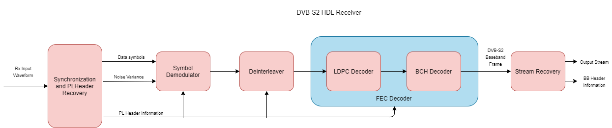
This section explains the high-level architecture of the DVB-S2 receiver model. The Synchronization and PLHeader Recovery block extracts the data symbols, estimates noise variance, and decodes physical layer (PL) header information from the Rx Input Waveform signal. The Symbol Demodulator block demodulates the data symbols and computes soft bits. The Deinterleaver block deinterleaves and FEC Decoder block decodes the soft bits to extract a DVB-S2 baseband frame signal. The Stream Recovery block extracts the BB header information and the output stream bits from the baseband frame.
This block diagram shows the high-level architecture of the model.
File Structure
This example uses four Simulink models, five MATLAB files, and one Simulink data dictionary.
dvbs2hdlReceiver.slx— Top-level Simulink model.dvbs2hdlSyncPLHeaderRecoveryCore.slx— Model reference that synchronizes time, frequency, and phase, and decode PL header.dvbs2hdlBBFrameRecoveryCore.slx— Model reference that demodulates the symbols, deinterleaves the demodulated soft bits, and decodes the deinterleaved soft bits using forward error correction (FEC). It discards the frames that does not support the configuration according to [ 1 ].dvbs2hdlStreamRecoveryCore.slx— Model reference that recovers the stream of data bits.getdvbs2LDPCParityMatrices.m— Download the MAT file that stores LDPC parity check matrices that are used to generate the receiver input waveform.dvbs2hdlRxParameters.m— Generate parameters for thedvbs2hdlSyncPLHeaderRecoveryCore.slxmodel reference.dvbs2hdlPhaseNoise.m— Introduce phase noise to the input sequence.dvbs2hdlRxInit.m— Generate the transmitter waveform and initialize thedvbs2hdlSyncPLHeaderRecoveryCore.slxmodel reference.dvbs2hdlReceiverVerify.m— Gather PL header parameters and stream recovered bits.dvbs2hdlReceiverData.sldd— Simulink data dictionary to store bus signal configurations.
System Interface
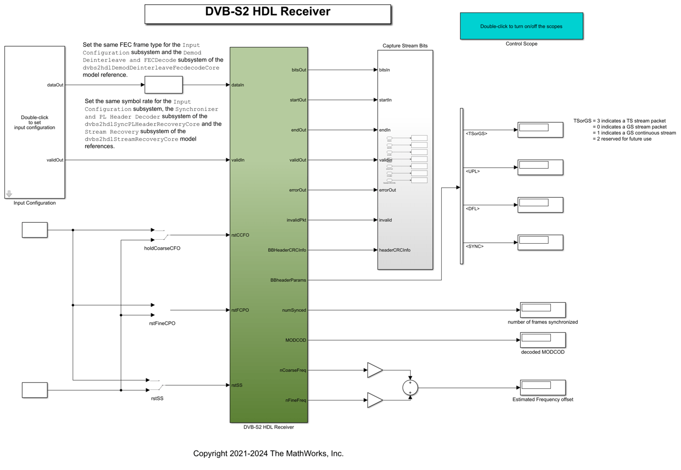
This figure shows the top-level overview of the dvbs2hdlReceiver.slx model.
Model Inputs
- dataIn — Input data, specified as an 18 bit complex data with a sample rate that is four times the symbol rate.
- validIn — Control signal to validate the dataIn, specified as a Boolean scalar.
- rstCCFO — Control signal to reset the coarse frequency compensation loops, specified as a Boolean scalar.
- rstFCPO — Control signal to reset the fine phase compensation loops, specified as a Boolean scalar.
Model Outputs:
- diagBus — Bus signal with diagnosis information.
- bitsOut — Decoded stream bits, returned as a Boolean scalar.
- startOut — Control signal for start of bitsOut stream bits, returned as a Boolean scalar.
- endOut — Control signal for end of bitsOut stream bits, returned as a Boolean scalar.
- validOut — Control signal to validate the bitsOut, returned as a Boolean scalar.
- errorOut — Control signal to indicate packet CRC failures. It can be ignored for non-packetized continuous streams.
- invalidPkt — Control signal to indicate invalid packets that can be discarded. It can be ignored for non-packetized continuous streams.
- headerCRCInfo — Header CRC status, returned as a 2 bit real data. MSB bit high indicates a CRC error, and LSB high indicates when the CRC is considered.
- numSynced — Number of frames synchronized, returned as a 32 bit scalar integer
- MODCOD — Decoded MODCOD, returned as a 5 bit scalar integer.
- nCoarseFreq — Estimated normalized (with sample rate) coarse frequency offset, returned as a 21 bit scalar.
- nFineFreq — Estimated normalized (with symbol rate) fine frequency offset, returned as a 21 bit scalar.
- BBHeaderParams — The following are the list of BB header parameters:
- TSorGS — Input stream format, returned as a 2 bit real data.
- SISorMIS — Single or multiple input stream input, returned as a Boolean scalar.
- CCMorACM — Constant coding modulation (CCM), or adaptive coding modulation (ACM) or variable coding modulation (VCM), returned as a Boolean scalar.
- RO — Roll-off factor, returned as a 2 bit real data.
- UPL — User packet length (UPL), returned as a 16 bit real data.
- DFL — Data field length (DFL), returned as a 16 bit real data.
- SYNC — SYNC word, returned as an 8 bit real data.
- ISSYI — Input stream synchronization indicator (ISSYI), returned as a Boolean scalar.
- NPD — Null packet detection (NPD), returned as a Boolean scalar.
- MIS_ISI — Input stream identifier (ISI) for multiple input stream input, returned as an 8 bit real data. For single stream, this is reserved by the standard.
- SYNCD — Start location of SYNC word in number of bits from start of data field, returned as a 16 bit real data.
Model Structure
This figure shows the top-level model of the DVB-S2 HDL Receiver subsystem. The subsystem comprises three model references, dvbs2hdlSyncPLHeaderRecoveryCore, dvbs2hdlBBFrameRecoveryCore, and dvbs2hdlStreamRecoveryCore.
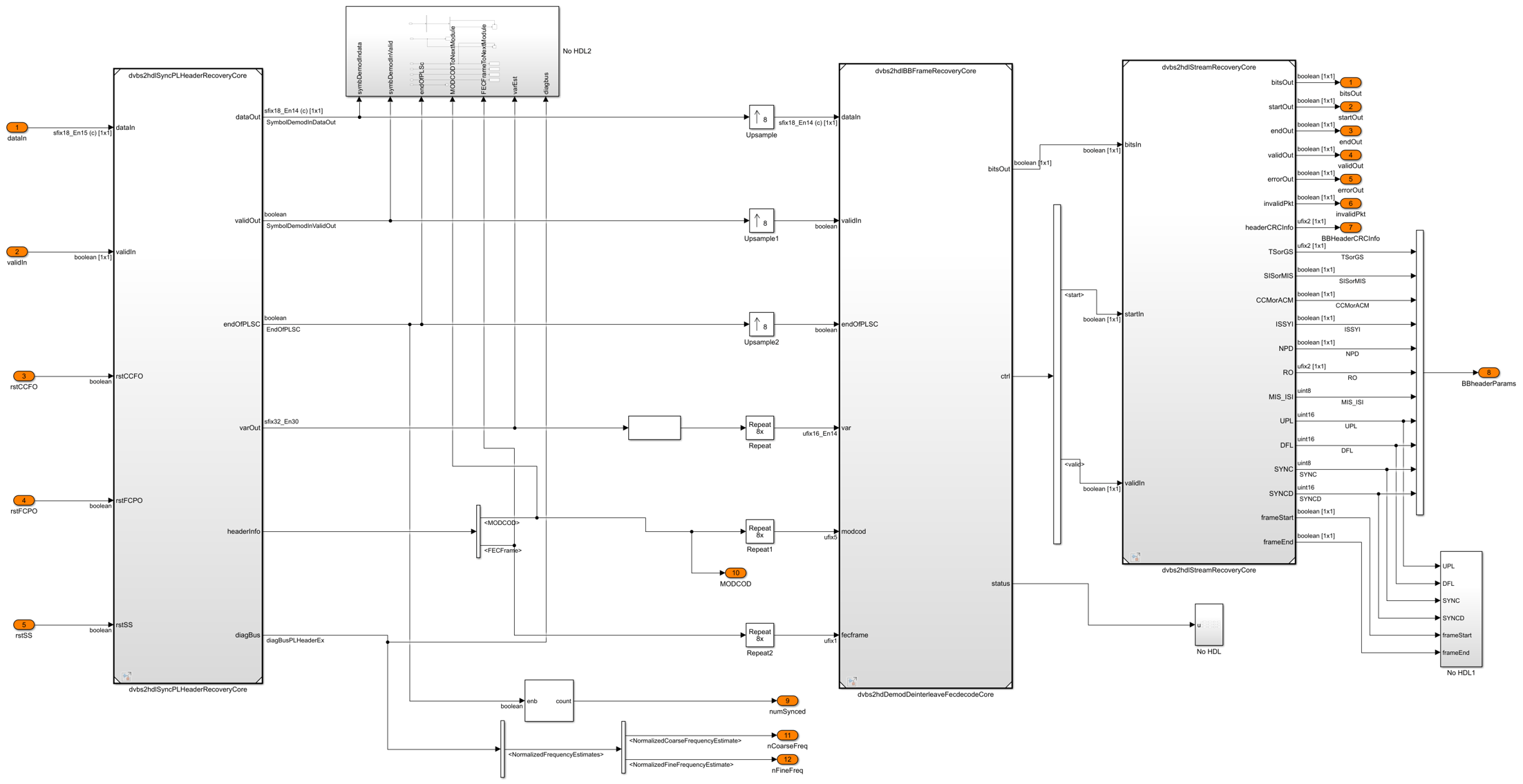
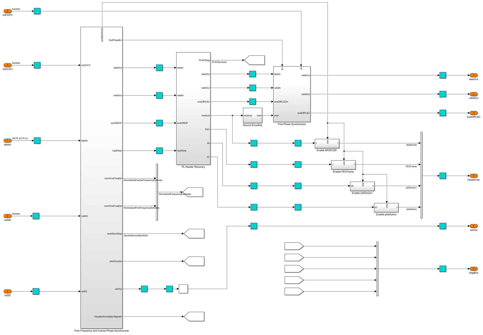
dvbs2hdlSyncPLHeaderRecoveryCore — Synchronizes the input receiver waveform, estimates noise variance, and decodes PL header information. For more information, see DVB-S2 HDL PL Header Recovery example.
dvbs2hdlBBFrameRecoveryCore — Demodulates the input symbols using DVB-S2 Symbol Demodulator block to extract soft bits, deinterleave the soft bits using DVB-S2 DeinterLeaver subsystem, and FEC decodes (LDPC and BCH decodes) the soft bits using the DVB-S2 LDPC Decoder block and the DVB-S2 BCH Decoder block to extract baseband frame (BBFrame). The baseband frame streams into the dvbs2hdlStreamRecoveryCore model reference.
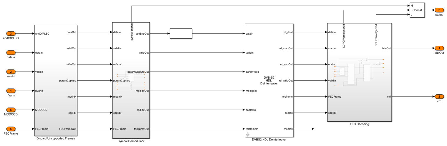
The DVB-S2 Deinterleaver subsystem in the dvbs2hdlBBFrameRecoveryCore model reference continuously stores the soft bits received from the DVB-S2 Symbol Demodulator inside the RAM subsystem. The RAM Address Generator subsystem generates the read and write logic to the RAM for deinterleaving.

In the RAM Address Generator subsystem, the nRows and nColumns subsystem stores the number of rows and columns of each of the possible configuration in look-up tables (LUT). Based on the PL header parameters, the number of rows and columns is decided for deinterleaving. The Read Offset Address subsystem generates the deinterleaver indices of each frame as an offset address. The Generate and Add Read Base Address subsystem adds the offset address with a base read address to get the actual address of the soft-bit stored in the RAM. The Parameter Store FIFO subsystem stores the PL header parameters and reads these parameters in synchronous with start of each frame.

This table shows the rows and columns considered for deinterleaving for each of the configurations.
Modulation Rows (Normal) Rows (Short) Columns
__________ _____________ ____________ _______
QPSK 64800 16200 1
8-PSK 21600 5400 3
16-APSK 16200 4050 4
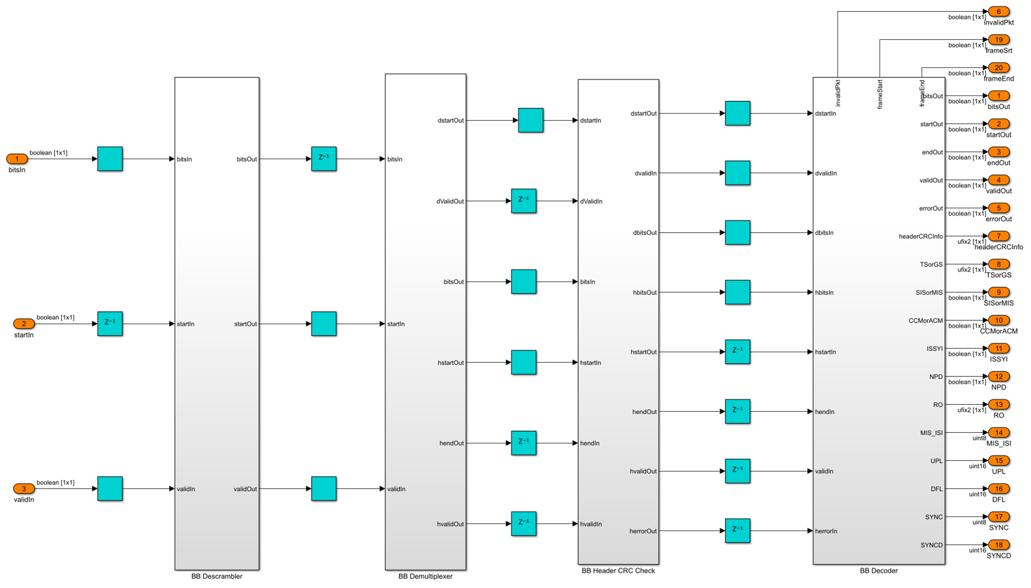
32-APSK 12960 3240 5 dvbs2hdlStreamRecoveryCore — Decodes the BB header and recovers the stream bits. The BB Descrambler subsystem descrambles the baseband frame. The BB Demultiplexer subsystem demultiplexes the descrambled frame into BB header and data bits. The BB Header CRC Check subsystem uses the General CRC Syndrome Detector HDL Optimized block to check the CRC status and discards the baseband frames that fails CRC check. The BB Decoder subsystem extracts the BB header information and the data field. For packetized stream of bits, the control signals are generated to indicate the start, end, and validity of bits for each packet. The General CRC Syndrome Detector HDL Optimized block checks the CRC status of each packet. For continuous stream of bits, the data field is passed on to the output.
Run the Model
Set the symbol rate, MODCOD, FECFrame type values, input stream format, user packet length and channel impairments on the mask of the Input Configuration subsystem and run the dvbs2hdlReceiver model. Alternatively, to run the model, execute this command at the MATLAB command window.
sim dvbs2hdlReceiver
The MODCOD value must be a row vector. Each element of the row vector corresponds to a frame.
Note: Use QPSK modulated frames initially to achieve time frequency and phase synchronization.
Verification and Results
Run the dvbs2hdlReceiver.slx model. The model utilizes 120 short QPSK frames for synchronization.
Searching for referenced models in model 'dvbs2hdlReceiver'.
Found 3 model reference targets to update.
Starting serial model reference simulation build.
Successfully updated the model reference simulation target for: dvbs2hdlBBFrameRecoveryCore
Successfully updated the model reference simulation target for: dvbs2hdlStreamRecoveryCore
Successfully updated the model reference simulation target for: dvbs2hdlSyncPLHeaderRecoveryCore
Build Summary
Model reference simulation targets:
Model Build Reason Status Build Duration
dvbs2hdlBBFrameRecoveryCore Target (dvbs2hdlBBFrameRecoveryCore_msf.mexw64) did not exist. Code generated and compiled. 0h 2m 47.546s dvbs2hdlStreamRecoveryCore Target (dvbs2hdlStreamRecoveryCore_msf.mexw64) did not exist. Code generated and compiled. 0h 1m 3.1162s dvbs2hdlSyncPLHeaderRecoveryCore Target (dvbs2hdlSyncPLHeaderRecoveryCore_msf.mexw64) did not exist. Code generated and compiled. 0h 4m 39.145s
3 of 3 models built (0 models already up to date) Build duration: 0h 9m 13.769s
Number of frames synced = 124 out of 124 Initial frames not compared = 120 Number of frames lost due to BB Header CRC failure = 0 out of 4 Number of packets lost due to packet CRC failure = 0 out of 27
HDL Code Generation
To generate the HDL code for this example, you must have HDL Coder™. Use makehdl and makehdltb commands to generate HDL code and HDL testbench for the DVB-S2 HDL Receiver subsystem. The testbench generation time depends on the simulation time.
The resulting HDL code is synthesized for a Xilinx® Zynq® UltraScale+ RFSoC ZCU111 board. The post place and route resource utilization are shown in this table. The maximum frequency of operation is 236 MHz.
  Resources      Usage
_____________    _____

CLB LUT          80434
CLB Registers    94549
RAMB36           235
RAMB18           46
DSP48            294
References
- ETSI Standard EN 302 307-1 V1.4.1(2014-11). Digital Video Broadcasting (DVB); Second Generation Framing Structure, Channel Coding and Modulation Systems for Broadcasting, Interactive Services, News Gathering and other Broadband Satellite Applications (DVB-S2).
- ETSI Standard TR 102 376-1 V1.2.1(2015-11). Digital Video Broadcasting (DVB); Implementation Guidelines for the Second Generation System for Broadcasting, Interactive Services, News Gathering and other Broadband Satellite Applications (DVB-S2).
See Also
Blocks
- DVB-S2 BCH Decoder | DVB-S2 LDPC Decoder | DVB-S2 Symbol Demodulator | General CRC Generator HDL Optimized | General CRC Syndrome Detector HDL Optimized