Multiply-Accumulate - Perform a multiply-accumulate operation on the inputs - Simulink (original) (raw)
Perform a multiply-accumulate operation on the inputs
Description
The Multiply-Accumulate block performs this operation on inputsa , b, and bias c to compute result dataOut.
By default, the block operates in the vector mode. The inputs a andb can be scalars, vectors, or 2-D matrices. By default, the bias value c is equal to zero. The block computes the dot product of inputs a and b. You can specify a nonzero value for c by using Dialog or Input port as the Source. The block adds this bias to the dot product of a and b. The multiplication operation is full precision irrespective of the Output data type setting. The Output data type and Integer rounding mode settings apply to the addition operation. To generate HDL code for the block, use vector inputs. For scalar inputs, use the Multiply-Add block.
By using the Operation Mode setting, you can specify streaming modes of operation for the Multiply-Accumulate block. For HDL code generation, when you use the streaming operation mode, you must input scalar values to the block. The block has two streaming modes: Streaming - using Start and End ports and Streaming - using Number of Samples. When you select these streaming modes, you can specify the control signals to use with the mode. The control signals specify when to start and end accumulation and when the output is valid.
Ports
Input
a — Input signal
vector | matrix | array | bus
Port to provide input to the block.
Data Types: single | double | int8 | int16 | int32 | uint8 | uint16 | uint32 | fixed point
b — Input signal
scalar | vector | matrix | array | bus
Port to provide input to the block.
Data Types: single | double | int8 | int16 | int32 | uint8 | uint16 | uint32 | Boolean | fixed point | enumerated | bus
c — Bias signal
scalar | vector | matrix | array | bus
Port to provide the bias signal to the block. The block adds this bias to the inputs. Make sure that the bias signal data type matches that of the dot product of the inputs.
Dependencies
To enable this port, set Source toInput port.
Data Types: single | double | int8 | int16 | int32 | uint8 | uint16 | uint32 | fixed point
startIn — Start of accumulation control signal
scalar | vector | matrix | array | bus
Port to provide the control signal to start accumulation. It is recommended that you use a boolean data type signal as input to the port. To start obtaining the accumulated output value from the dataOut signal, bothstartIn and validIn signals must be high. The dataOut signal produces the accumulated result from the next clock cycle.
Dependencies
To enable this port, set Operation Mode toStreaming - using Start and End Ports.
Data Types: single | double | int8 | int16 | int32 | uint8 | uint16 | uint32 | fixed point
validIn — Valid input control signal
scalar | vector | matrix | array | bus
Port to provide the control signal to indicate that the input signal is valid for accumulation. It is recommended that you use aboolean data type signal as input to the port. To start obtaining the accumulated output value from thedataOut signal, bothvalidIn and startIn signals must be high. The dataOut signal produces the accumulated result from the next clock cycle. ThevalidIn signal has higher priority thanstartIn and endIn signals.
Dependencies
To enable this port, set Operation Mode toStreaming - using Start and End Ports or Streaming - using Number of Samples.
Data Types: single | double | int8 | int16 | int32 | uint8 | uint16 | uint32 | fixed point
endIn — End of accumulation control signal
scalar | vector | matrix | array | bus
Port to provide the control signal to indicate end of accumulation. You can use the startIn andendIn signals with thevalidIn signal to indicate a frame that contains the accumulated output.
Dependencies
To enable this port, set Operation Mode toStreaming - using Start and End Ports and then select End input and output ports.
Data Types: single | double | int8 | int16 | int32 | uint8 | uint16 | uint32 | fixed point
Output
dataOut — Output signal
scalar | vector | matrix | array | bus
Port that generates the output data from the multiply-accumulate operation. By default, the block uses theVector mode of operation and computes the dot product of the input signals, and adds the bias to produce the result. If you specify a streaming mode of operation asOperation Mode, the value of thedataOut signal depends on the control signals that you provide. The data type of the output signal is same as that of the accumulator.
Data Types: single | double | int8 | int16 | int32 | uint8 | uint16 | uint32 | fixed point
startOut — Start of accumulation output control signal
scalar | vector | matrix | array | bus
Port that generates output control signal to indicate the start of accumulation. When both validIn andstartIn are high, thestartOut signal becomes high in the next clock cycle. The clock cycle at which startOut becomes high indicates the start of a frame and that thedataOut signal has started producing valid accumulated output.
Dependencies
To enable this port, set Operation Mode toStreaming - using Start and End Ports and then select Start output port.
Data Types: single | double | int8 | int16 | int32 | uint8 | uint16 | uint32 | fixed point
validOut — Valid output control signal
scalar | vector | matrix | array | bus
Port that generates the output control signal to indicate that thedataOut signal is valid. When thevalidIn signal becomes high , thevalidOut signal becomes high in the next clock cycle and indicates that the dataOut is valid.
Dependencies
To enable this port, set Operation Mode toStreaming - using Start and End Ports and then select Valid output port.
Data Types: single | double | int8 | int16 | int32 | uint8 | uint16 | uint32 | fixed point
endOut — End of accumulation output control signal
scalar | vector | matrix | array | bus
Port that generates the output control signal to indicate the end of accumulation. You can use the clock cycles between when thestartOut signal becomes high and when theendOut signal becomes high to indicate a valid frame that contains the accumulated output.
Dependencies
To enable this port, set Operation Mode toStreaming - using Start and End Ports and then select End input and output ports.
Data Types: single | double | int8 | int16 | int32 | uint8 | uint16 | uint32 | fixed point
countOut — Count output control signal
scalar | vector | matrix | array | bus
Port that generates the output control signal to indicate number of samples to accumulate. The value of this signal increases from1 to the value that you specify forNumber of Samples. As long as thevalidIn signal is high, thecountOut increments by 1 every clock cycle.
Dependencies
To enable this port, set Operation Mode toStreaming - using Number of Samples and then select Count output port.
Data Types: single | double | int8 | int16 | int32 | uint8 | uint16 | uint32 | fixed point
Parameters
Operation Mode — Mode of accumulation of inputs
'Vector' (default) | 'Streaming - using Start and End Ports' | 'Streaming - using Number of Samples'
You can specify the Operation Mode as:
Vector: You can use scalars or vectors as inputs. The block performs the dot product of the inputsu1andu2and adds biaskto produce the result.Streaming - using Start and End Ports: Use scalar inputs for HDL code generation. In this mode, you can use thestartIn and endIn control signals to determine when to start and stop accumulation. The output data is valid whenvalidIn is high.Streaming - using Number of Samples: Use scalar inputs for HDL code generation. In this mode, you can specify the Number of Samples and use thecountIn control signal to determine when to start and stop accumulation. The output data is valid when validIn is high.
Programmatic Use
| Block parameter: opMode | |
|---|---|
| Type: character vector | |
| Value: 'Vector' | 'Streaming - using Start and End Ports' | 'Streaming - using Number of Samples' |
| Default: 'Vector' |
Bias — Offset to add to the input dot product
{'0.0'} (default)
You can specify the bias with:
- Source as
Dialog. Then, specify the Value. - Source as
Input port. This setting creates an external input portcto input the bias signal to the block.
Programmatic Use
| Block parameter: initValueSetting |
|---|
| Type: character vector |
| Value: 'Dialog' | 'Input port' |
| Default: 'Dialog' |
If you set Source as Dialog, you can specify the initial value by using theinitValue2 setting.
| Block parameter: initValue2 |
|---|
| Type: character vector |
| Value: An integer greater than or equal to zero |
| Default: '0.0' |
Number of Samples — Number of samples of valid accumulated output signal
{'2'} (default)
You can specify the Number of Samples to specify a frame containing the number of samples of valid accumulated outputdataOut.
Dependencies
To enable this port, set Operation Mode toStreaming - using Number of Samples.
Programmatic Use
| Block parameter: num_samples |
|---|
| Type: character vector |
| Value: An integer greater than or equal to zero |
| Default: '2' |
Output data type — Data type of the block output
Inherit: Inherit via back propagation (default)
Set the output data type to:
- A rule that inherits a data type, such as
Inherit: Same as first input. - A built-in data type, such as
singleorint16. - The name of a data type object. for instance, a
Simulink.NumericTypeobject. - An expression that evaluates to a valid data type, for example,
fixdt(1,16,0)
The streaming modes do not support Inherit: Inherit via internal rule. When you set the Output data type, you can use the Data Type Assistant. To display the assistant, click the Show data type assistant  .
.
Programmatic Use
| Block parameter: OutDataTypeStr |
|---|
| Type: character vector |
| Default: {'Inherit: Inherit via internal rule'} |
To see possible values that you can specify for this parameter, seeProgrammatically Specify Block Parameters and Properties.
Integer rounding mode — Rounding mode for fixed-point operations
Floor (default) | Ceiling | Convergent | Nearest | Round | Simplest | Zero
Specify the rounding action as:
Ceiling
Rounds positive and negative numbers toward positive infinity. Equivalent to the MATLAB® ceil function.
Convergent
Rounds number to the nearest representable value. If a tie occurs, rounds to the nearest even integer. Equivalent to the Fixed-Point Designer™convergent function.
Floor
Rounds positive and negative numbers toward negative infinity. Equivalent to the MATLABfloor function.
Nearest
Rounds the number to the nearest representable value. If a tie occurs, rounds toward positive infinity. Equivalent to the Fixed-Point Designernearest function.
Round
Rounds number to the nearest representable value. If a tie occurs, rounds positive numbers toward positive infinity and rounds negative numbers toward negative infinity. Equivalent to the Fixed-Point Designerround function.
Simplest
Chooses between rounding toward floor and rounding toward zero to generate rounding code that is as efficient as possible.
Zero
Rounds number toward zero. Equivalent to the MATLABfix function.
Programmatic Use
| Block parameter: RndMeth |
|---|
| Type: character vector |
| Default: {'Floor'} |
To see possible values that you can specify for this parameter, seeProgrammatically Specify Block Parameters and Properties.
Valid output port — Control generation of validOut output port
off (default) | on
Control generation of the validOut output port. This port indicates whether dataOut is valid.
 off
off
Does not display the validOut output port.
 on
on
Display the validOut output port.
Dependencies
To enable this port, set Operation Mode toStreaming - using Number of Samples orStreaming - using Start and End Ports.
Programmatic Use
| Block parameter: validOut |
|---|
| Type: character vector |
| Values: 'off' | 'on' |
| Default: 'off' |
End input and output ports — Control generation of endIn input port and endOut output port
off (default) | on
Control generation of the endIn input port and theendOut output port. The ports indicate the end of a frame containing valid accumulation output.
off
Does not display the endIn input port and the endOut output port.
on
Display the endIn input port and theendOut output port.
Dependencies
To enable this port, set Operation Mode toStreaming - using Start and End Ports.
Programmatic Use
| Block parameter: endInandOut |
|---|
| Type: character vector |
| Values: 'off' | 'on' |
| Default: 'off' |
Start output port — Control generation of startOut output port
off (default) | on
Control generation of the startOut output port. This port generates the startOut signal that indicates the start of a frame containing valid accumulated output.
off
Does not display the startOut output port.
on
Display the startOut output port.
Dependencies
To enable this port, set Operation Mode toStreaming - using Start and End Ports.
Programmatic Use
| Block parameter: startOut |
|---|
| Type: character vector |
| Values: 'off' | 'on' |
| Default: 'off' |
Count output port — Control generation of countOut output port
off (default) | on
Control generation of the countOut output port. This port generates the counter that indicates a frame containing valid samples.
off
Does not display the countOut output port.
on
Display the countOut output port.
Dependencies
To enable this port, set Operation Mode toStreaming - using Number of Samples.
Programmatic Use
| Block parameter: countOut |
|---|
| Type: character vector |
| Values: 'off' | 'on' |
| Default: 'off' |
Tips
With the Multiply-Accumulate block, you can:
- Perform matrix multiplication operations. For example, if you have two matrix inputs with dimensions
N-by-MandM-by-P, you can compute the result by usingN-by-Pmultiply-accumulate operations in parallel. - Replace a sequence of multiplication and addition operations, such as in filter blocks, and improve the performance on hardware by mapping to DSP slices on the FPGA. This figure shows how you can use the Multiply-Accumulate block with the
sfir_fixedmodel.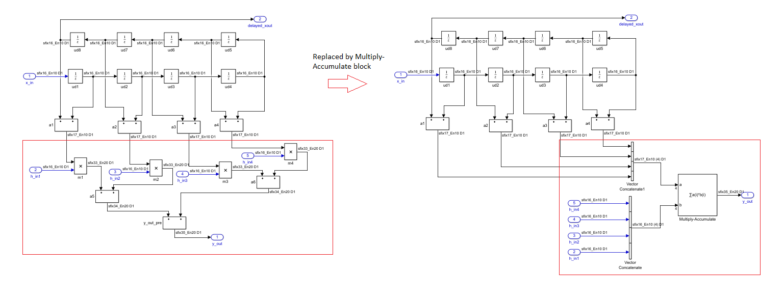
Algorithms
Streaming Mode Using Start and End Ports
You can use the Operation Mode setting for the block to specify a streaming mode of operation. When you select Streaming - using Start and End Ports, you see three additional settings enabled by default. The settings include:
- Valid output port
- End input and output ports
- Start output port
It is recommended that you leave these settings enabled. When you apply the settings, three additional input ports and three additional output ports appear:
| Input Ports | Output Ports |
|---|---|
| startIn | startOut |
| validIn | validOut |
| endIn | endOut |
This figure illustrates the streaming mode of operation using the start and end ports. In this example, the bias value is 8.
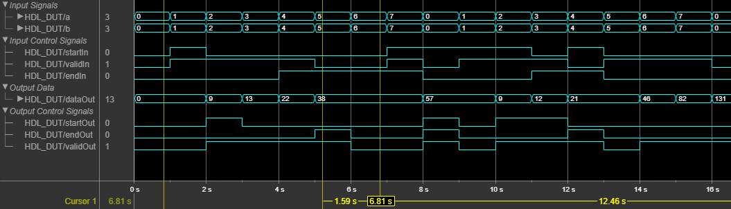
Initially, when validIn is low, dataOut is zero. At time 1s, both startIn andvalidIn become high. Therefore,validOut becomes high in the next clock cycle anddataOut starts producing valid accumulation output. During accumulation, dataOut takes the values ofa and b from the previous clock cycle. For example, at time t = 2s, dataOut = 1*1 + 8 = 9.
To continue accumulation, make startIn low at the next clock cycle and keep validIn high. dataOut continues accumulating the inputs until validIn becomes low. At each time step, dataOut computes the product of the inputs from the previous clock cycle and sums the result with the dataOut value from the previous clock cycle. For example, at time t = 3s,dataOut = 2*2 + 9 = 13.
When validIn becomes low, dataOut holds the output value as seen at time t = 5s. At t = 5s, endIn andvalidIn are high. Therefore, endOut becomes high in the next clock cycle, which indicates end of frame. Therefore the frame between t = 2s (when startOut is high) and t = 6s (whenendOut is high) indicates a frame containing valid output.
If startIn, validIn, andendIn are both high at the same time, only thedataOut corresponding to those inputs are accumulated as seen at t = 8s. If startIn is high for multiple clock cycles, and if validIn is high, the accumulator is reset at each clock cycle as seen at t = 10s and t = 11s. The accumulation continues at t = 12s.
Streaming Mode Using Number of Samples
You can use the Operation Mode setting for the block to specify a streaming mode of operation. When you select Streaming - using Number of Samples, you see two additional settings enabled by default. The settings include:
- Valid output port
- Count output port
It is recommended that you leave these settings enabled. When you apply the settings, you have an additional input port validIn and three additional output ports appear:
- endOut
- validOut
- countOut
This figure illustrates the streaming mode of operation using the number of samples. In this example, the bias value is 8 and theNumber of Samples is 5.
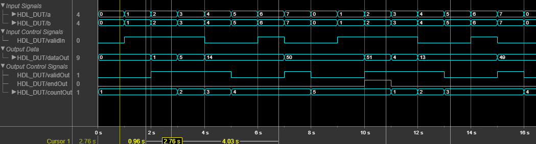
Initially, when validIn is low, dataOut is 0 and countOut is 1. At time 1s, validIn becomes high. Therefore,validOut becomes high in the next clock cycle, anddataOut starts producing valid accumulation output. During accumulation, dataOut takes the values ofa and b from the previous clock cycle. For example, at time t = 2s, dataOut = 1*1 =1. countOut increments by1 at the next clock cycle, that is, at t =3s, countOut becomes2.
To continue accumulation, keep validIn high.dataOut continues accumulating the inputs untilvalidIn becomes low. When five valid outputs are obtained from dataOut, countOut becomes5 and endOut becomes high, which indicates the end of the frame. Therefore, the time between whencountOut is 1 and whencountOut is five indicates a frame containing valid output.
The accumulator counter is now reset and countOut starts from1. When validIn becomes high again,dataOut starts accumulating a new set of values andcountOut starts incrementing for each validdataOut.
Extended Capabilities
C/C++ Code Generation
Generate C and C++ code using Simulink® Coder™.
HDL Code Generation
Generate VHDL, Verilog and SystemVerilog code for FPGA and ASIC designs using HDL Coder™.
HDL Coder™ provides additional configuration options that affect HDL implementation and synthesized logic.
HDL Architecture
| HDL Architecture Setting | Description |
|---|---|
| Parallel | For input vectors of size N, this mode uses N Multiply-Add blocks in series to compute the result. This mode uses a combinatorial implementation and does not introduce any latency. If you specify the Synthesis tool and Target frequency, since the adaptive pipelining optimization is enabled, the code generator inserts pipeline registers for the Multiply-Add blocks. When you synthesize your design, depending on the input bit widths, this architecture maps up to N DSP slices on the FPGA. |
| Serial(Default) | For input vectors of size N, this mode uses a streaming algorithm to implement the multiply-accumulate operation. This architecture has two implementation modes: The default mode uses a local multirate implementation. This implementation overclocks the shared resources by N and multiplexes the input vectors with aMultiply-Add block. This implementation introduces an additional latency of one at the data rate. If you have clock-rate pipelining enabled on the model or subsystem that contains theMultiply-Accumulate block, this architecture uses a single-rate implementation. This implementation runs the shared resources at the clock-rate and multiplexes the input vectors with a Multiply-Add block. This implementation introduces an additional latency ofN at the clock rate.When you synthesize your design, depending on the input bit widths, this architecture maps to one DSP slice on the FPGA. |
HDL Block Properties
| General | |
|---|---|
| ConstrainedOutputPipeline | Number of registers to place at the outputs by moving existing delays within your design. Distributed pipelining does not redistribute these registers. The default is0. For more details, see ConstrainedOutputPipeline. |
| InputPipeline | Number of input pipeline stages to insert in the generated code. Distributed pipelining and constrained output pipelining can move these registers. The default is0. For more details, see InputPipeline. |
| OutputPipeline | Number of output pipeline stages to insert in the generated code. Distributed pipelining and constrained output pipelining can move these registers. The default is0. For more details, see OutputPipeline. |
Complex Data Support
When you use complex signals, this block can generate HDL code, but does not map to DSP slices.
Reset Type Recommendation
For the mapping of theMultiply-Accumulate block to DSP slices, use these reset type settings:
- For Xilinx® FPGA boards, set Reset type to
Synchronous. - For Altera® FPGA boards, set Reset type to
Asynchronous.
To set the reset type, select > > > .
Limitations
- Matrix data types are not supported at the block port interfaces. If you have matrix type signals, use the Product, Matrix Multiply block in matrix multiplication mode.
- Streaming modes of operation for the block are not supported inside a Resettable Subsystem block for HDL code generation.
- The block does not support floating-point data types for HDL code generation.
Version History
Introduced in R2017b