HDL Block Properties: General - MATLAB & Simulink (original) (raw)
Overview
Block implementation parameters enable you to control details of the code generated for specific block implementations. See Set and View HDL Model and Block Parameters to learn how to select block implementations and parameters in the GUI or the command line.
Property names are specified as character vectors. The data type of a property value is specific to the property. This section describes the syntax of each block implementation parameter and how the parameter affects generated code.
HDL Block Properties of Library Blocks
HDL block properties of library blocks are treated similar to mask parameters. When you instantiate library blocks in your model, the current HDL block properties of that library block are copied to instances of that block in your model. The HDL block properties of these instances are not synchronized with the HDL block properties of the library block. That is, if you change the HDL block property of the library block, the change does not get propagated to instances of the library block that you already added to your Simulink® model. If you want the HDL block properties of a library block to be synchronized with its instances in the model, create a Subsystem and then place this block inside that Subsystem. The HDL block properties of blocks that reside inside the library block are synchronized with the corresponding instances in your model.
Suppose a library contains a Subsystem block with HDL architecture set to Module. When you instantiate this block in your model, the block instance uses Module as the HDL architecture. If you change the HDL architecture of the Subsystem block in the library toBlackBox, existing instances of that Subsystem block in your model still use Module as the HDL architecture. If you now add instances of the Subsystem block from the library in your model, the new block instances get a copy of the current HDL block properties, and therefore useBlackBox as the HDL architecture. If you want the HDL architecture of the Subsystem block in the library to be synchronized with its instances in the model, create a wrapper subsystem with the HDL architecture that you want inside thisSubsystem.
AdaptivePipelining
The AdaptivePipelining subsystem parameter enables you to set adaptive pipelining on a subsystem within a model.
| Adaptive Pipelining Setting | Description |
|---|---|
| 'inherit' (default) | Use the adaptive pipelining setting of the parent subsystem. If this subsystem is the highest-level subsystem, use the adaptive pipelining setting for the model. |
| 'on' | Insert adaptive pipelines for this subsystem. |
| 'off' | Do not insert adaptive pipelines for this subsystem, even if the parent subsystem has adaptive pipelining enabled. |
To disable adaptive pipelining for a subsystem within a model, set the adaptive pipelining parameter, AdaptivePipelining, to 'off' for that subsystem.
To learn how to set model-level adaptive pipelining, see Adaptive pipelining.
Set Adaptive Pipelining For a Subsystem
To set adaptive pipelining for a subsystem from the HDL Block Properties dialog box:
- Right-click the subsystem and select > .
- For AdaptivePipelining, select , , or .
To set adaptive pipelining for a subsystem from the command line, usehdlset_param. For example, to turn off adaptive pipelining for a subsystem, my_dut:
hdlset_param('my_dut', 'AdaptivePipelining', 'off')
See also hdlset_param.
AllowDelayDistribution
Use the AllowDelayDistribution property of a Delay or Unit Delay block to allow the delay block to be moved for the distributed pipelining optimization or absorbed during delay absorption.
| Allow Delay Distribution Setting | Description |
|---|---|
| 'inherit' (default) | Use the Allow design delay distribution setting of the model. |
| 'on' | Allow the delay block to be moved or absorbed in optimizations. |
| 'off' | Do not allow the delay block to be moved or absorbed in optimizations. |
Set Allow Delay Distribution For a Delay or Unit Delay Block
To set whether a Delay or Unit Delay block is distributed or absorbed during distributed pipelining or delay absorption from the HDL Block Properties dialog box:
- Right-click the subsystem and select > .
- Set AllowDelayDistribution to
inherit,on, oroff.
To set delay distribution for a Delay or Unit Delay block from the command line, use hdlset_param. For example, to not allow delay distribution for a Delay block,'my_DUT/Delay1':
hdlset_param('my_DUT/Delay1','AllowDelayDistribution','off')
See also hdlset_param.
See Also
BalanceDelays
The BalanceDelays subsystem parameter enables you to set delay balancing on a subsystem within a model.
| BalanceDelays Setting | Description |
|---|---|
| 'inherit' (default) | Use the delay balancing setting of the parent subsystem. If this subsystem is the highest-level subsystem, use the delay balancing setting for the model. |
| 'on' | Balance delays for this subsystem. |
| 'off' | Do not balance delays for this subsystem, even if the parent subsystem has delay balancing enabled. |
To learn more about delay balancing, see Delay Balancing.
Set Delay Balancing For a Subsystem
To set delay balancing for a subsystem using the HDL Block Properties dialog box:
- Right-click the subsystem.
- Select > .
- For BalanceDelays, select , , or .
To set delay balancing for a subsystem from the command line, usehdlset_param. For example, to turn off delay balancing for a subsystem, my_dut:
hdlset_param('my_dut', 'BalanceDelays', 'off')
See also hdlset_param.
ClockRatePipelining
The ClockRatePipelining subsystem parameter enables you to set clock-rate pipelining on a subsystem within a model.
| Clock-Rate Pipelining Setting | Description |
|---|---|
| 'inherit' (default) | Use the clock-rate pipelining setting of the parent subsystem. If this subsystem is the highest-level subsystem, use the clock-rate pipelining setting for the model. |
| 'on' | Insert clock-rate pipelines for this subsystem. |
| 'off' | Do not insert clock-rate pipelines for this subsystem, even if the parent subsystem has clock-rate pipelining enabled. |
To disable clock-rate pipelining for a subsystem within a model, setClockRatePipelining to off for that subsystem.
To learn how to set model-level clock-rate pipelining, see Clock-rate pipelining.
Set Clock-Rate Pipelining For a Subsystem
To set clock-rate pipelining for a subsystem using the HDL Block Properties dialog box:
- Right-click the subsystem.
- Select > .
- Set ClockRatePipelining to
inherit,on, oroff.
To set clock-rate pipelining for a subsystem from the command line, use hdlset_param. For example, to turn off clock-rate pipelining for a subsystem, my_dut:
hdlset_param('my_dut', 'ClockRatePipelining', 'off')
See Also
CodingStyle
When you use Multiport Switch blocks, use theCodingStyle parameter to specify whether you want to generate HDL code with if-else or case statements. By default, HDL Coder™ generates if-else statements. If you have several Multiport Switch blocks in your model, you can choose to specify a differentCodingStyle for each block.
| CodingStyle Setting | Description |
|---|---|
| 'ifelse_stmt'(Default) | Generate if-else statements in the Verilog or SystemVerilog code or when-else statements in the VHDL code for a Multiport Switch block. |
| 'case_stmt' | Generate case statements in the Verilog or SystemVerilog code or case-when statements in the VHDL code for a Multiport Switch block. |
Set CodingStyle For Multiport Switch Block
To set CodingStyle for a Multiport Switch using the HDL Block Properties dialog box:
- Right-click the Multiport Switch block.
- Select > .
- For CodingStyle, select
ifelse_stmtorcase_stmt.
To see the CodingStyle specified for a subsystem from the command line, use hdlget_param. For example, to see the settings specified for a Multiport Switch block inside a subsystem,my_dut:
hdlget_param('my_dut/Multiport Switch', 'CodingStyle')
See also hdlset_param.
ConstMultiplierOptimization
The ConstMultiplierOptimization implementation parameter lets you specify use of canonical signed digit (CSD) or factored CSD optimizations for processing coefficient multiplier operations in the generated code.
The following table shows the ConstMultiplierOptimization parameter values.
| ConstMultiplierOptimization Setting | Description |
|---|---|
| 'none'(Default) | By default, HDL Coder does not perform CSD or FCSD optimizations. Code generated for the Gain block retains multiplier operations. |
| 'CSD' | When you specify this option, the generated code decreases the area used by the model while maintaining or increasing clock speed, using canonical signed digit (CSD) techniques. CSD replaces multiplier operations with add and subtract operations. CSD minimizes the number of addition operations required for constant multiplication by representing binary numbers with a minimum count of nonzero digits. |
| 'FCSD' | This option uses factored CSD (FCSD) techniques, which replace multiplier operations with shift and add/subtract operations on certain factors of the operands. These factors are generally prime but can also be a number close to a power of 2, which favors area reduction. This option lets you achieve a greater area reduction than CSD, at the cost of decreasing clock speed. |
| 'auto' | When you specify this option, HDL Coder chooses between the CSD or FCSD optimizations. The coder chooses the optimization that yields the most area-efficient implementation, based on the number of adders required. When you specify 'auto', the coder does not use multipliers, unless conditions are such that CSD or FCSD optimizations are not possible (for example, if the design uses floating-point arithmetic). |
The ConstMultiplierOptimization parameter is available for the following blocks:
- Gain
- Stateflow® chart
- Truth Table
- MATLAB Function
- MATLAB System
ConstrainedOutputPipeline
Use the ConstrainedOutputPipeline parameter to specify a nonnegative number of registers to be moved to the block outputs.
Constrained output pipelining does not add registers, but instead redistributes existing delays within your design to try to meet the constraint. If HDL Coder cannot meet the constraint with existing delays, it reports the difference between the number of desired and actual output registers in the Timing and Area report. Distributed pipelining does not redistribute registers you specify with constrained output pipelining.
How to Specify Constrained Output Pipelining
To specify constrained output pipelining for a block using the GUI:
- Right-click the block and select > .
- For ConstrainedOutputPipeline, enter the number of registers you want in your subsystem.
To specify constrained output pipelining, at the command line, enter:
hdlset_param(path_to_block, 'ConstrainedOutputPipeline', number_of_output_registers)
For example, to constrain 6 registers at the output ports of a subsystem,subsys, in your model, mymodel, enter:
hdlset_param('mymodel/subsys','ConstrainedOutputPipeline', 6)
See Also
DistributedPipelining
The DistributedPipelining subsystem parameter enables pipeline register distribution, which is a speed optimization that increases your clock speed by reducing your critical path on a subsystem. This optimization moves the delays within a subsystem while preserving the hierarchy.
| DistributedPipelining Setting | Description |
|---|---|
| 'inherit' (default) | Use the distributed pipelining setting of the parent subsystem. If this subsystem is the highest-level subsystem, use the distributed pipelining setting for the model. |
| 'off' | HDL Coder does not distribute the pipeline registers placed manually or by using the HDL block properties InputPipeline or OutputPipeline. |
| 'on' | HDL Coder distributes registers inside the subsystem, MATLAB Function block, or Stateflow chart based on critical path analysis. This setting distributes the pipelines in the subsystem that are already placed manually or by using the HDL Block Properties InputPipeline or OutputPipeline. |
Tip
Output data might be in an invalid state initially if you insert pipeline registers. To avoid test bench errors resulting from initial invalid samples, disable output checking for those samples. For more information, see Ignore output data checking (number of samples).
To enable distributed pipelining for a subsystem within a model, setDistributedPipelining to on for that subsystem.
To learn how to set model-level distributed pipelining, see Distributed pipelining.
Set Distributed Pipelining For a Subsystem
To set distributed pipelining for a subsystem using the HDL Block Properties dialog box:
- Right-click the subsystem.
- Select > .
- Set DistributedPipelining to
inherit,on, oroff.
To set distributed pipelining for a subsystem from the command line, use the hdlset_param function. For example, enter:
hdlset_param('path/to/subsystem', 'DistributedPipelining', 'on')
See Also
- Distributed Pipelining
- Distributed Pipelining: Speed Optimization
- Use Distributed Pipelining Optimization in Models with MATLAB Function Blocks
DotProductStrategy
If you use the Product block for matrix multiplication in your design, use the DotProductStrategy to specify how you want to implement the matrix multiplication.
The DotProductStrategy options are listed in the following table.
| DotProductStrategy Value | Description |
|---|---|
| 'Fully Parallel' (default) | Expands the matrix multiplication operation into multipliers and adders. For example, if you multiply two 2x2 matrices, the implementation uses eight multipliers and four adders to compute the result.To share the multipliers to optimize area, use the HDL block property StreamingFactor.NoteThe DotProductStrategy must be set to 'Fully Parallel' when you use the Native Floating Point mode. |
| 'Fully Parallel Scalarized' | Expands the matrix multiplication operation into multipliers and adders. For example, if you multiply two 2x2 matrices, the implementation uses eight multipliers and four adders to compute the result. Use this option for smaller sized matrices and when you want to enable sharing on both the multipliers and adders.To share the multipliers to optimize area, use the HDL block property SharingFactor. |
| 'Serial Multiply-Accumulate' | Uses the Serial architecture of the Multiply-Accumulate block to implement the matrix multiplication.In this architecture, the clock rate must be faster than the clock rate that you specify with Parallel architecture. You can see the clock rate in the Clock Summary information of the Code Generation report. |
| 'Parallel Multiply-Accumulate' | Uses the Parallel architecture of the Multiply-Accumulate block to implement the matrix multiplication. |
DSPStyle
DSPStyle enables you to generate code that includes synthesis attributes for multiplier mapping in your design. You can choose whether to map a particular block’s multipliers to DSPs or logic in hardware.
For Xilinx® targets, the generated code uses the use_dsp attribute. For Altera® targets, the generated code uses the multstyle attribute.
The DSPStyle options are listed in the following table.
| DSPStyle Value | Description |
|---|---|
| 'none' (default) | Do not insert a DSP mapping synthesis attribute. |
| 'on' | Insert synthesis attribute that directs the synthesis tool to map to DSPs in hardware. |
| 'off' | Insert synthesis attribute that directs the synthesis tool to map to logic in hardware. |
The DSPStyle parameter is available for the following blocks:
- Gain
- Product
- Product of Elements with Architecture set to Tree
- Subsystem
- Atomic Subsystem
- Variant Subsystem
- Enabled Subsystem
- Triggered Subsystem
- Model with Architecture set to
ModelReference
Hierarchy Flattening Behavior
If you specify hierarchy flattening for a subsystem that also has a nondefaultDSPStyle setting, HDL Coder propagates the DSPStyle setting to the parent subsystem.
If the flattened subsystem contains Gain, Product, orProduct of Elements blocks, the coder keeps their nondefaultDSPStyle settings, and replaces defaultDSPStyle settings with the flattened subsystemDSPStyle setting.
Synthesis Attributes in Generated Code
The generated code for synthesis attributes depends on:
- Target language
DSPStylevalueSynthesisToolvalue
The following table shows examples of synthesis attributes in generated code.
| DSPStyle Value | TargetLanguage Value | SynthesisTool Value | |
|---|---|---|---|
| 'Altera Quartus II' | 'Xilinx ISE' 'Xilinx Vivado' | ||
| 'none' | 'Verilog' | wire signed [32:0] m4_out1; | wire signed [32:0] m4_out1; |
| 'VHDL' | m4_out1 : signal; | m4_out1 : signal; | |
| 'on' | 'Verilog' | (* multstyle = "dsp" *) wire signed [32:0] m4_out1; | (* use_dsp = "yes" *) wire signed [32:0] m4_out1; |
| 'VHDL' | attribute multstyle : string ;attribute multstyle of m4_out1 : signal is "dsp" ; | attribute use_dsp : string ;attribute use_dsp of m4_out1 : signal is "yes" ; | |
| 'off' | 'Verilog' | (* multstyle = "logic" *) wire signed [32:0] m4_out1; | (* use_dsp = "no" *) wire signed [32:0] m4_out1; |
| 'VHDL' | attribute multstyle : string ;attribute multstyle of m4_out1 : signal is "logic" ; | attribute use_dsp : string ;attribute use_dsp of m4_out1 : signal is "no" ; |
Requirement For Synthesis Attribute Specification
You must specify a synthesis tool by using the SynthesisTool property.
How To Specify a Synthesis Attribute
To specify a synthesis attribute using the HDL Block Properties dialog box:
- Right-click the block.
- Select > .
- For DSPStyle, select , , or .
To specify a synthesis attribute from the command line, usehdlset_param. For example, suppose you have a model,my_model, with a DUT subsystem, my_dut, that contains a Gain block, my_multiplier. To insert a synthesis attribute to map my_multiplier to a DSP, enter:
hdlset_param('my_model/my_dut/my_multiplier', 'DSPStyle', 'on')
See also hdlset_param.
Limitations For Synthesis Attribute Specification
- When you specify a nondefault
DSPStyleblock property, theConstMultiplierOptimizationproperty must be set to'none'. - Inputs to multiplier components cannot use the
doubledata type. - Gain constant cannot be a power of 2.
FlattenHierarchy
FlattenHierarchy enables you to remove subsystem hierarchy from the HDL code generated from your design.
| FlattenHierarchy Setting | Description |
|---|---|
| 'inherit' (default) | Use the hierarchy flattening setting of the parent subsystem. If this subsystem is the highest-level subsystem, do not flatten. |
| 'on' | Flatten this subsystem. |
| 'off' | Do not flatten this subsystem, even if the parent subsystem is flattened. |
To flatten hierarchy, you must also have the MaskParameterAsGeneric global property set to 'off'. For more information, see Generate parameterized HDL code from masked subsystem.
How To Flatten Hierarchy
To set hierarchy flattening using the HDL Block Properties dialog box:
- In the Apps tab, select HDL Coder. The HDL Code tab appears. Select theSubsystem and then click . For FlattenHierarchy, select , , or .
- Right-click the Subsystem and select > . ForFlattenHierarchy, select , , or .
To set hierarchy flattening from the command line, use hdlset_param. For example, to turn on hierarchy flattening for a subsystem, my_dut:
hdlset_param('my_dut', 'FlattenHierarchy', 'on')
See also hdlset_param.
Limitations For Hierarchy Flattening
A subsystem cannot be flattened if the subsystem is:
- A Synchronous Subsystem or uses the State Control block in
Synchronousmode. - A model reference implementation.
- A Triggered Subsystem when Use trigger signal as clock is enabled.
GuardIndexVariables
GuardIndexVariables enables you to specify whether to hoist array indices out of conditional statements or not. When you enable certain optimizations such as RAM Mapping, loop streaming, sharing, and so on, expressions are moved out of the array indices. A temporary variable is created for the expression that might result in an index out-of- bounds error during simulation. When you enable this option the generated code might be inefficient for your target hardware.
| GuardIndexVariables Setting | Description |
|---|---|
| 'off' (default) | Move the expression for array indices out of the conditional statement and create a temporary variable for the expression. |
| 'on' | Do not move the expression for array indices out of the conditional statement and do not create a temporary variable for the expression. |
This image shows the generated code with the option enabled and disabled. When theGuardIndexVariable option is off, the array index variable i is not decided by the conditional loop and might go out of bounds. When the GuardIndexVariable option is on, the array index variable idx is decided by the conditional loop preventing an array index out of bounds error during simulation.
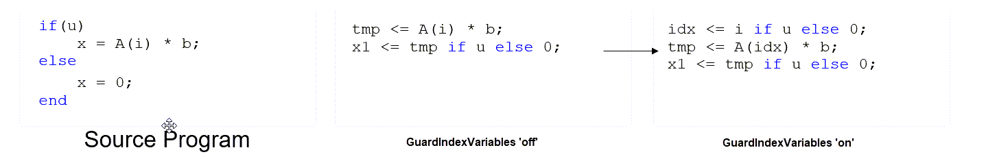
If you get an index access violation error during simulation, use this option.
InputPipeline
InputPipeline lets you specify an implementation with input pipelining for selected blocks. The parameter value specifies the number of input pipeline stages (pipeline depth) in the generated code. Distributed pipelining can move input pipelines to optimize your design. To prevent distributed pipelining from moving input pipelines from a specified point in your design, use the ConstrainedOutputPipeline parameter.
The following code specifies an input pipeline depth of two stages for each Sum block in the model:
sblocks = find_system(gcb, 'BlockType', 'Sum'); for ii=1:length(sblocks),hdlset_param(sblocks{ii},'InputPipeline', 2), end;
Note
The InputPipeline setting does not have any effect on blocks that do not have an input port.
When generating code for pipeline registers, HDL Coder appends a postfix string to names of input or output pipeline registers. The default postfix string is _pipe. To customize the postfix string, use thePipeline postfix option in the Global Settings / General pane in the HDL Code Generation pane of the Configuration Parameters dialog box. Alternatively, you can pass the desired postfix as a character vector in the makehdl property PipelinePostfix. For an example, see Pipeline postfix.
InstantiateFunctions
For the MATLAB Function block, you can use the InstantiateFunctions parameter to generate a VHDL® entity, Verilog® or SystemVerilog module for each function. HDL Coder generates code for each entity or module in a separate file.
The InstantiateFunctions options for the MATLAB Function block are listed in the following table.
| InstantiateFunctions Setting | Description |
|---|---|
| 'off' (default) | Generate code for functions inline. |
| 'on' | Generate a VHDLentity, Verilog or SystemVerilog module for each function, and save each module orentity in a separate file. |
How To Generate Instantiable Code for Functions
To set the InstantiateFunctions parameter using the HDL Block Properties dialog box:
- Right-click the MATLAB Function block.
- Select > .
- For InstantiateFunctions, select on.
To set the InstantiateFunctions parameter from the command line, use hdlset_param. For example, to generate instantiable code for functions in a MATLAB Function block, myMatlabFcn, in your DUT subsystem, myDUT, enter:
hdlset_param('my_DUT/my_MATLABFcnBlk', 'InstantiateFunctions', 'on')
Generate Code Inline for Specific Functions
If you want to generate instantiable code for some functions but not others, enable the option to generate instantiable code for functions, and use coder.inline. See coder.inline for details.
Limitations for Instantiable Code Generation for Functions
The software generates code inline when:
- Function calls are within conditional code or
forloops. - Any function is called with a nonconstant
structinput. - The function has state, such as a persistent variable, and is called multiple times.
- There is an enumeration anywhere in the design function.
InstantiateStages
For a Cascade architecture, you can use theInstantiateStages parameter to generate a VHDLentity or Verilogmodule for each computation stage. HDL Coder generates code for each entity or module in a separate file.
| InstantiateStages Setting | Description |
|---|---|
| 'off' (default) | Generate cascade stages in a single VHDLentity or Verilogmodule. |
| 'on' | Generate a VHDLentity or Verilogmodule for each cascade stage, and save eachmodule or entity in a separate file. |
LoopOptimization
LoopOptimization enables you to stream or unroll loops in code generated from a MATLAB Function block. Loop streaming optimizes for area; loop unrolling optimizes for speed.
| LoopOptimization Setting | Description |
|---|---|
| 'none' (default) | Do not optimize loops. |
| 'Unrolling' | Unroll loops. |
| 'Streaming' | Stream loops. |
How to Optimize MATLAB Function Block For Loops
To select a loop optimization using the HDL Block Properties dialog box:
- Right-click the MATLAB Function block.
- Select > .
- For LoopOptimization, select
none,Unrolling, orStreaming.
To select a loop optimization from the command line, usehdlset_param. For example, to turn on loop streaming for aMATLAB Function block, my_mlfn:
hdlset_param('my_mlfn', 'LoopOptimization', 'Streaming')
See also hdlset_param.
Limitations for MATLAB Function Block Loop Optimization
HDL Coder cannot stream a loop if:
- The loop index counts down. The loop index must increase by 1 on each iteration.
- There are 2 or more nested loops at the same level of hierarchy within another loop.
- Any particular persistent variable is updated both inside and outside a loop.
HDL Coder can stream a loop when the persistent variable is:
- Updated inside the loop and read outside the loop.
- Read within the loop and updated outside the loop.
LUTRegisterResetType
Use the LUTRegisterResetType block parameter to control synthesis of a LUT into a ROM structure on an FPGA.
| LUTRegisterResetType Value | Description |
|---|---|
| default | LUT output register has default reset logic. When you generate HDL, the LUT will be synthesized as registers. |
| none | LUT output register has no reset logic. When you generate HDL, the LUT will be synthesized as a ROM. |
You can specify LUTRegisterResetType for the following blocks:
- Gamma Correction
- Lookup Table
MapPersistentVarsToRAM
With the MapPersistentVarsToRAM implementation parameter, you can use RAM-based mapping for persistent arrays of a MATLAB Function block instead of mapping to registers.
| MapPersistentVarsToRAM Setting | Mapping Behavior |
|---|---|
| off | Persistent arrays map to registers in the generated HDL code. |
| on | Persistent array variables map to RAM. For restrictions, see RAM Mapping Restrictions. |
RAM Mapping Restrictions
When you enable RAM mapping, a persistent array or user-defined System object™ private property maps to a block RAM when all of these conditions are true:
- Each read or write access is for a single element only. For example, submatrix access and array copies are not supported.
- Address computation logic is not read-dependent. For example, computation of a read or write address using the data read from the array is not supported.
- Persistent variables or user-defined System object private properties are initialized to 0 if they have a cyclic dependency. For example, if you have two persistent variables, A and B, you have a cyclic dependency if A depends on B, and B depends on A.
- If an access is within a conditional statement, the conditional statement uses only simple logic expressions (
&&,||,~) or relational operators. For example, in this code,r1does not map to RAM:
if (mod(i,2) > 0)
a = r1(u);
else
r1(i) = u;
end
You can rewrite complex conditions, such as conditions that call functions, by assigning them to temporary variables, and using the temporary variables in the conditional statement. For example, to mapr1to RAM, rewrite the previous code as:
temp = mod(i,2);
if (temp > 0)
a = r1(u);
else
r1(i) = u;
end - The persistent array or user-defined System object private property value depends on external inputs.
For example, in the following code,bigarraydoes not map to RAM because it does not depend onu:
function z = foo(u)
persistent cnt bigarray
if isempty(cnt)
cnt = fi(0,1,16,10,hdlfimath);
bigarray = uint8(zeros(1024,1));
end
z = u + cnt;
idx = uint8(cnt);
temp = bigarray(idx+1);
cnt(:) = cnt + fi(1,1,16,0,hdlfimath) + temp;
bigarray(idx+1) = idx; - The RAM size is greater than or equal to the
RAMMappingThresholdvalue. The RAM size is the product ofArray Size * Word Length * Complexity, where:Array Sizeis the number of elements in the array.Word Lengthis the number of bits that represent the data type of the array.Complexityis 2 for a complex data type or 1 for a real datatype.
- Access to the persistent variable that you are mapping to RAM is not in a loop, such as a
forloop, unless the loop is unrolled. For more information, see coder.unroll. - Access to the persistent variable that you are mapping to RAM is not in a nested conditional statement, such as a nested
ifstatement or nestedswitchstatement.
If any of the above conditions is false, the persistent array or user-defined System object private property maps to a register in the HDL code.
RAMMappingThreshold
The default value of RAMMappingThreshold is256. To change the threshold, use hdlset_param. For example, the following command changes the mapping threshold for thesfir_fixed model to 128 bits:
hdlset_param('sfir_fixed', 'RAMMappingThreshold', 128);
You can also change the RAM mapping threshold in the Configuration Parameters dialog box. For more information, see RAM mapping threshold.
Example
For an example that shows how to map persistent array variables to RAM in aMATLAB Function block, see RAM Mapping with the MATLAB Function Block.
MapToRAM
Use the MapToRAM property to map lookup tables (LUT) to RAM.
When Simulate RAM Delay is enabled, theMapToRAM property is disabled for the Sine HDL Optimized and Cosine HDL Optimized block.
| MapToRAM Setting | Mapping Behavior |
|---|---|
| inherit (default) | The model setting Map lookup tables to RAM behavior is used. |
| off | The block lookup tables (LUTs) are mapped to logic slices on the FPGA. |
| on | The block lookup tables (LUTs) are mapped to RAM. |
MapToRAM Considerations for Added Latency
When you enable either the block property MapToRAM or the global option LUTMapToRAM and the synthesis tool for the model isXilinx or Altera, a unit delay without reset is added after the Lookup Table block. Because of the added unit delay, additional latency is inserted and delay balanced in the generated HDL Code and generated model. To avoid extra latency, you can add a Delay block with the HDL Block property ResetType set to none after theLookup Table block in the original model.
OutputPipeline
OutputPipeline lets you specify an implementation with output pipelining for selected blocks. The parameter value specifies the number of output pipeline stages (pipeline depth) in the generated code. Distributed pipelining can move output pipelines to optimize your design. To prevent distributed pipelining from moving output pipelines from a specified point in your design, use the ConstrainedOutputPipeline parameter.
This code specifies an output pipeline depth of two stages for each Sum block in the model:
sblocks = find_system(gcb, 'BlockType', 'Sum'); for ii=1:length(sblocks),hdlset_param(sblocks{ii},'OutputPipeline', 2), end;
Note
The OutputPipeline setting does not have any effect on blocks that do not have an output port.
When generating code for pipeline registers, HDL Coder appends a postfix string to names of input or output pipeline registers. The default postfix string is _pipe. To customize the postfix string, use thePipeline postfix option in the Configuration Parameters dialog box, in the HDL Code Generation > Global Settings > General tab. Alternatively, you can use the PipelinePostfix property withmakehdl. For an example, see Pipeline postfix.
See also Use Distributed Pipelining Optimization in Models with MATLAB Function Blocks.
PreserveUpstreamLogic
Control the removal of unconnected logic. Unconnected logic is logic that is connected upstream from a terminator block. This property is available forTerminator blocks only.
| PreserveUpstreamLogic Options | PreserveUpstreamLogic Behavior |
|---|---|
| off (default) | Logic connected upstream from the Terminator block is not preserved in HDL code generation. |
| on | Logic connected upstream from the Terminator block is preserved in HDL code generation. |
For an example, see the "Upstream Logic Preservation of Unused Port" section of Optimize Unconnected Ports in HDL Code for Simulink Models.
RAMDirective
Using RAMDirective, you can specify whether you want to map the Random Access Memory (RAM) blocks in your Simulink model to FPGA RAM memory blocks. You can map large memory blocks such asultra from the Xilinx family and M144k from the Quartus® family. Specify these RAMDirective values for the RAM blocks in your design based on the synthesis tool.
| Synthesis Tool | RAM Style Attribute | RAMDirective Values |
|---|---|---|
| Quartus | ramstyle | logic| M9K |
| Xilinx | ram_style | block| distributed |
| Microchip | syn_ramstyle | block_ram| registers |
When you specify a value for this setting, HDL Coder generates a ramstyle attribute in the HDL code. This attribute specifies the type of RAM memory unit that you want the synthesis tool to use when inferring the RAM blocks in your design.
When you do not specify a value for this setting, HDL Coder does not generate the ramstyle attribute in the HDL code. The synthesis tool determines the type of inferred RAM for mapping the RAM blocks in your model.
Set RAMDirective for RAM Blocks
In the HDL RAMs library, except for the Dual Rate Dual Port RAM, you can specify the RAMDirective property for all other RAM blocks.
To set RAMDirective for a RAM block in the HDL Block Properties dialog box:
- Right-click the RAM block.
- Select > .
- In RAMDirective property, specify the values as listed in the table.
You can also set the RAMDirective by usinghdlset_param function.
hdlset_param(, ‘RAMDirective’, );
To specify these attributes in the MATLAB® HDL workflow, use the RAMDirective parameter value pair for hdl.RAM instantiation. Set this property by using this command:
hRam = hdl.RAM(‘RAMType’, ‘Single Port RAM’, ‘RAMDirective’, ‘ultra’);
For example, generate an HDL attribute for mapping the RAM blocks in your model toblock RAM. A block RAM is a dedicated memory unit on the FPGA. Sizes of block RAMs can be 4kb, 8kb,16kb, and 32kb.
To map your RAM blocks to block RAM:
- Specify the synthesis tool. You must target a Xilinx device that contains
block RAMresources. If the target device does not contain block RAMs, the synthesis tool ignores this attribute and might infer the RAM as distributed RAMs or Lookup Table (LUT) slices. - Enter the RAMDirective value as
blockfor your Simulink RAM blocks in HDL Block Properties. - Generate the HDL code for your model.
This generated VHDL code shows the ram_style attribute is set toblock:
attribute ram_style: string; attribute ram_style of ram : signal is "block";
This generated Verilog or SystemVerilog code shows the ram_style attribute is set toblock:
(* ram_style = "block" *)
Dependency
When using RAMDirective property, make sure to select the synthesis tool for your design.
ResetType
Use the ResetType block parameter to suppress reset logic generation.
| ResetType Value | Description |
|---|---|
| default | Generate reset logic. |
| none | Do not generate reset logic.Reset is not applied to generated registers. Therefore, mismatches between Simulink and the generated code occur for some number of samples during the initial phase, when registers are not fully loaded.To avoid test bench errors during the initial phase, determine the number of samples required to fully load the registers. Then, set the Ignore output data checking (number of samples) option accordingly. See also Ignore output data checking (number of samples). |
You can specify ResetType for the following blocks:
- Chart
- Convolutional Deinterleaver
- Convolutional Interleaver
- Delay
- Delay (DSP System Toolbox™)
- General Multiplexed Deinterleaver
- General Multiplexed Interleaver
- MATLAB Function
- MATLAB System
- Memory
- Tapped Delay
- Truth Table
- Unit Delay Enabled
- Unit Delay
Reset Logic for Optimizations in the MATLAB Function Block
When you set ResetType to none for aMATLAB Function block, HDL Coder does not generate reset logic for persistent variables in the MATLAB code.
However, if you specify other optimizations for the block, the coder may insert registers that use reset logic. The coder does not suppress reset logic generation for these registers. Therefore, if you set ResetType tonone along with other block optimizations, your generated code may have a reset port at the top level.
How to Suppress Reset Logic Generation
To suppress reset logic generation for a block using the UI:
- Right-click the block and select > .
- For ResetType, select
none.
To suppress reset logic generation, on the command line, enter:
hdlset_param(path_to_block,'ResetType','none')
For example, to suppress reset logic generation for a Unit Delay block,UnitDelay1, within a subsystem, mySubsys, on the command line, enter:
hdlset_param('mySubsys/UnitDelay1','ResetType','none');
Specify Synchronous or Asynchronous Reset
To specify a synchronous or asynchronous reset, use the ResetType model-level parameter. For details, see Reset type.
SerialPartition
Use this parameter on Min/Max blocks to specify partitions for a serial cascade architecture. The default setting uses the minimum number of partitions.
| To Generate This Architecture... | Set SerialPartition to... |
|---|---|
| Cascade-serial with explicitly specified partitioning | [p1 p2 p3...pN]: a vector of N integers, where N is the number of serial partitions. Each element of the vector specifies the length of the corresponding partition. The sum of the vector elements must be equal to the length of the input data vector. The values of the vector elements must be in descending order, except the last two elements can be equal. For example, for an input of 8 elements, partitions [5 3] or [4 2 2] are legal, but the partitions [2 2 2 2] or [3 2 3] raise an error at code generation time. |
| Cascade-serial with automatically optimized partitioning | 0 |
This property is also used for serial filter architectures. For how to configure filter blocks, see SerialPartition.
SharingFactor
Use SharingFactor to specify the number of functionally equivalent resources to map to a single shared resource. The default is 0. See Resource Sharing.
SoftReset
Use the SoftReset block parameter to specify whether to generate hardware-friendly synchronous reset logic, or local reset logic that matches the Simulink simulation behavior. This property is available for the Unit Delay Resettable block or Unit Delay Enabled Resettable block.
| SoftReset Value | Description |
|---|---|
| off (default) | Generate local reset logic that matches the Simulink simulation behavior. |
| on | Generate synchronous reset logic for the block. This option generates code that is more efficient for synthesis, but does not match the Simulink simulation behavior. |
When SoftReset set to 'off', the following code is generated for a Unit Delay Resettable block :
always @(posedge clk or posedge reset) begin : Unit_Delay_Resettable_process if (reset == 1'b1) begin Unit_Delay_Resettable_zero_delay <= 1'b1; Unit_Delay_Resettable_switch_delay <= 2'b00; end else begin if (enb) begin Unit_Delay_Resettable_zero_delay <= 1'b0; if (UDR_reset == 1'b1) begin Unit_Delay_Resettable_switch_delay <= 2'b00; end else begin Unit_Delay_Resettable_switch_delay <= In1; end end end end
assign Unit_Delay_Resettable_1 = (UDR_reset || Unit_Delay_Resettable_zero_delay ? 1'b1 : 1'b0); assign out0 = (Unit_Delay_Resettable_1 == 1'b1 ? 2'b00 : Unit_Delay_Resettable_switch_delay);
When SoftReset set to 'on', the following code is generated for a Unit Delay Resettable block :
always @(posedge clk or posedge reset) begin : Unit_Delay_Resettable_process if (reset == 1'b1) begin Unit_Delay_Resettable_reg <= 2'b00; end else begin if (enb) begin if (UDR_reset != 1'b0) begin Unit_Delay_Resettable_reg <= 2'b00; end else begin Unit_Delay_Resettable_reg <= In1; end end end end
assign out0 = Unit_Delay_Resettable_reg;
StreamingFactor
Number of parallel data paths, or vectors, to transform into serial, scalar data paths by time-multiplexing serial data paths and sharing hardware resources. The default is 0, which implements fully parallel data paths. See also Streaming.
UseRAM
The UseRAM implementation parameter enables using RAM-based mapping for a Delay block instead of mapping to a shift register.
| UseRAM Setting | Mapping Behavior |
|---|---|
| off | The delay maps to a shift register in the generated HDL code, except in one case. For details, see Effects of Streaming and Distributed Pipelining. |
| on | The delay maps to a dual-port RAM block when the following conditions are true:Initial value of the delay is zero.The Delay block does not have an external reset or enable port.Delay length greater than or equal to4.Delay has one of the following set of numeric and data type attributes:(a) Real scalar with a non-floating-point data type (such as signed integer, unsigned integer, fixed point, or Boolean)(b) Complex scalar with real and imaginary parts that use non-floating-point data type(c) Vector where each element is either (a) or (b)RAMSize is greater than or equal to theRAMMappingThreshold value. RAMSize is the product of DelayLength * WordLength * VectorLength * Complexity.DelayLength is the number of delays that the Delay block specifies.WordLength is the number of bits that represent the data type of the delay.VectorLength is the vector length of the input to the Delay block.Complexity is 2 for a complex data type or 1 for a real datatype.For more information, see RAM mapping threshold.If any condition is false, the delay maps to a shift register in the HDL code unless it merges with other delays to map to a single RAM. For more information, see Mapping Multiple Delays to RAM. |
This implementation parameter is available for the Delay block in the Simulink Discrete library and the Delay (DSP System Toolbox) block in the DSP System Toolbox Signal Operations library.
Mapping Multiple Delays to RAM
HDL Coder can also merge several delays of equal length into one delay and then map the merged delay to a single RAM. This optimization provides the following benefits:
- Increased occupancy on a single RAM
- Sharing of address generation logic, which minimizes duplication of identical HDL code
- Mapping of delays to a RAM when the individual delays do not satisfy the threshold
The following rules control whether or not multiple delays can merge into one delay:
- The delays must:
- Be at the same level of the subsystem hierarchy.
- Use the same compiled sample time.
- Have
UseRAMset toon, or be generated by streaming or resource sharing. - Have the same
ResetTypesetting, which cannot benone.
- The
RAMSizeof the merged delay is greater than or equal to theRAMMappingThresholdvalue.RAMSizeis the product ofDelayLength * WordLength * VectorLength * Complexity.
Example of Multiple Delays Mapping to a Block RAM
RAMMappingThreshold for this model is 100 bits.
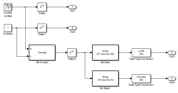
The Delay and Delay1 blocks merge and map to a dual-port RAM in the generated HDL code by satisfying the following conditions:
- Both delay blocks:
- Are at the same level of the hierarchy.
- Use the same compiled sample time.
- Have UseRAM set to
onin the HDL block properties dialog box. - Have the same ResetType setting of
default.
- The total word length of the merged delay is 28 bits.
- The
RAMSizeof the merged delay is 112 bits (4 delays * 28-bit word length), which is greater than the mapping threshold of 100 bits.
When you generate HDL code for this model, HDL Coder generates additional files to specify RAM mapping. HDL Coder stores these files in the same source location as other generated HDL files, for example, the hdlsrc folder.
Effects of Streaming and Distributed Pipelining
When UseRAM is off for a Delay block, HDL Coder maps the delay to a shift register by default. However, the coder changes the UseRAM setting to on and tries to map the delay to a RAM under the following conditions:
- Streaming is enabled for the subsystem with theDelay block.
- Distributed pipelining is disabled for the subsystem with theDelay block.
Suppose that distributed pipelining is enabled for the subsystem with the Delay block.
- When
UseRAMisoff, theDelay block participates in retiming. - When
UseRAMison, theDelay block does not participate in retiming. HDL Coder does not break up a delay marked for RAM mapping.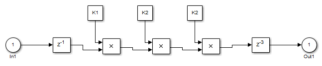
Model contains subsystem with two Delay blocks, threeConstant blocks, and three Product blocks. WhenUseRAMisonfor the Delay block on the right, that delay does not participate in retiming.
The following summary describes whether or not HDL Coder tries to map a delay to a RAM instead of a shift register.
| UseRAM Setting for the Delay Block | Optimizations Enabled for Subsystem with Delay Block | ||
|---|---|---|---|
| Distributed Pipelining Only | Streaming Only | Both Distributed Pipelining and Streaming | |
| On | Yes | Yes | Yes |
| Off | No | Yes, because mapping to a RAM instead of a shift register can provide an area-efficient design. | No |
VariablesToPipeline
The VariablesToPipeline parameter enables you to insert a pipeline register at the output of one or more MATLAB variables. Specify a list of variables as a character vector, with spaces separating the variables.
See also Pipeline MATLAB Expressions.
SynthesisAttributes
The SynthesisAttributes property enables you to generate code that includes custom synthesis attributes for the HDL Coder supported blocks in your design.
How To Specify a Synthesis Attribute
To specify a synthesis attribute from the command line, usehdlset_param. For example, suppose you have a model,my_model, with a DUT subsystem, my_dut, that contains a Delay block, my_delay.
- To set a block synthesis attribute on the
my_delayblock, enter:
hdlset_param(['my_model/my_dut/my_delay'], 'SynthesisAttributes', ...
{{'max_fanout', '5'}}); - To set a signal synthesis attributes on the output signals of the
my_delayblock, enter:
hdlset_param(['my_model/my_dut/my_delay'], 'SynthesisAttributes', ...
{{}, {{'mark_debug', 'true'}}}; - To set both the block and signal output synthesis attributes on the
my_delayblock, enter:
hdlset_param(['my_model/my_dut/my_delay'], 'SynthesisAttributes', ...
{{{'max_fanout', '5'}}, {{'mark_debug', 'true'}}};
See also hdlset_param.
For an example, see Configure Custom Synthesis Attributes for Simulink Blocks.
Synthesis Attributes in Generated Code
The generated code for synthesis attributes depends on synthesis tool and it is independent of target language.
The following table shows examples of synthesis attributes in generated code.
| Block | Synthesis Attributes Value | Target Language | |
|---|---|---|---|
| VHDL | Verilog / SystemVerilog | ||
| Delay | {{{'syn_radhardlevel', 'tmr'}, {'syn_maxfan', '5'}}, {{'syn_keep', 'true'}}} | ATTRIBUTE syn_maxfan : integer; ATTRIBUTE syn_radhardlevel : string; ATTRIBUTE syn_keep : boolean;ATTRIBUTE syn_maxfan OF Delay_reg : SIGNAL IS 5; ATTRIBUTE syn_radhardlevel OF Delay_reg : SIGNAL IS "tmr"; ATTRIBUTE syn_keep OF Delay_out1 : SIGNAL IS true; | (* syn_maxfan = 5, syn_radhardlevel = "tmr" *) vector_of_signed_logic_32 Delay_reg [0:1]; /* sfix32 [2] */ (* syn_keep = "true" *) logic signed [31:0] Delay_out1; /* int32 */ |
| Gain | {{'syn_multstyle', 'dsp'}} | ATTRIBUTE syn_multstyle : string;ATTRIBUTE syn_multstyle OF Gain_out1 : SIGNAL IS "dsp"; | (* syn_multstyle = "dsp" *) logic signed [63:0] Gain_out1; /* sfix64_En30 */ |
| Dual Port RAM System | {{{'ram_style', 'block'}, {'cascade_height', '4'}}, {{'mark_debug', 'true'}}, {{'mark_debug', 'true'}}} | ATTRIBUTE mark_debug : boolean;ATTRIBUTE cascade_height : integer; ATTRIBUTE ram_style : string; ATTRIBUTE cascade_height OF ram : SIGNAL IS 4; ATTRIBUTE ram_style OF ram : SIGNAL IS "block"; ATTRIBUTE mark_debug OF Dual_Port_RAM_System_out1 : SIGNAL IS true;ATTRIBUTE mark_debug OF Dual_Port_RAM_System_out2 : SIGNAL IS true; | (* cascade_height = 4, ram_style = "block" *) reg[DataWidth - 1:0] ram [2**AddrWidth - 1:0];(* mark_debug = "true" *) logic [15:0] Dual_Port_RAM_System_out1; /* uint16 */(* mark_debug = "true" *) logic [15:0] Dual_Port_RAM_System_out2; /* uint16 */ |
| Subsystem | {{'keep_hierarchy', 'true'}} | ATTRIBUTE keep_hierarchy : boolean;ATTRIBUTE keep_hierarchy OF rtl : ARCHITECTURE IS true; | (* keep_hierarchy = "true" *)module Subsystem( input logic clk,input logic clk_enable,input logic [15:0] In1 /* uint16 */,input logic [15:0] In1 /* uint16 */,input logic Input_rsvd,output logic ce_out,output logic [15:0] Out1 /* uint16 */,output logic [15:0] Output_rsvd /* uint16 */); |