Basic Guidelines for Modeling HDL Algorithm in Simulink - MATLAB & Simulink (original) (raw)
Use these guidelines to develop your HDL algorithm in Simulink®. The guidelines include using HDL-supported blocks when modeling your design and how to partition your design when developing the algorithm.
Each guideline has a severity level that indicates the level of compliance requirements. To learn more, see HDL Modeling Guidelines Severity Levels.
Use HDL-Supported Blocks
Guideline ID
1.1.1
Severity
Strongly Recommended
Description
When you create your Simulink model, use blocks from the > library. Several blocks in this library are pre-configured for HDL code generation. Blocks in this library are available with Simulink. If you do not have HDL Coder™, you can simulate the blocks in your model, but cannot generate HDL code.
You can find additional HDL-supported blocks in these Simulink block libraries:
- DSP System Toolbox HDL Support
- Communications Toolbox HDL Support
- Vision HDL Toolbox
- Wireless HDL Toolbox
To display only HDL-supported blocks in the Library Browser:
- in the Apps tab, select HDL Coder. The HDL Code tab appears. Select > .
- Alternatively, at the MATLAB® Command Window, enter hdllib.

To restore the library browser to the default view, enter this command:
Note
The set of supported blocks will change in future releases, so you should rebuild your supported blocks library each time you install a new version of this product.
Partition Model into DUT and Test Bench
Guideline ID
1.1.2
Severity
Recommended
Description
When you create your Simulink model for HDL code generation, the Subsystem that you want to generate HDL code for is the Design-Under-Test (DUT). This Subsystem contains Simulink blocks that can be implemented on your target FPGA or ASIC device. You can further partition the logic inside the DUT into smaller subsystems based on functionality, sample rates in your design, and so on. When you generate HDL code, the DUT becomes the top-level module or entity, and the Subsystems inside the DUT become submodules or smaller entities.
Blocks outside the DUT Subsystem become part of the test bench. The test bench can consist of blocks that are not supported for HDL code generation. Simulate the test bench to:
- Verify the functionality of the DUT in your Simulink model.
- Verify functional equivalence of the generated model with your original model.
For example, if you open the Simulink model template Blank_DUT, this model opens in the Simulink Editor.
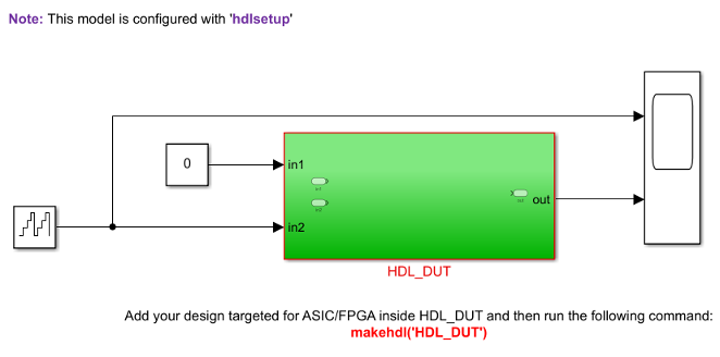
In this model, HDL_DUT Subsystem is the DUT and blocks outside this Subsystem form the test bench. You can develop your HDL algorithm inside the HDL_DUT Subsystem. This template model is preconfigured for HDL code generation.
Note
You can also generate HDL code for the entire model instead of the DUT Subsystem. Replace the input signals and Constant blocks withInport blocks. Replace the output signals and Scope blocks with Outport blocks.
Avoid Using Double-Byte Characters
Guideline ID
1.1.3
Severity
Strongly Recommended
Description
Downstream synthesis and simulation tools do not support double-byte characters such as Japanese and Chinese characters. HDL Coder does not support using:
- Double-byte characters in model and block names.
- Reserved words of your Operating System in model and block names such as
CR,con,prn,aux,ptr,null,ipt1,ipt2,ipt3, andipt4,com1,com2,com3, andcom4. - Double-byte characters in comments because the comments are propagated to the generated code. Use English comments instead.
Document Model Features and Attributes
Guideline ID
1.1.4
Severity
Recommended
Description
To make the generated HDL code easier to manage, you can document reference information as part of your model settings in these ways:
- Custom File Headers and Footer Comments in HDL Code for Design and Testbench
In the > > tab of the Configuration Parameters dialog box, by using the Custom File Header Comment andCustom File Footer Comment parameters, you can enter your own custom comments to appear as headers or footers in all generated HDL files. To learn more, see Custom File Header Comment and Custom File Footer Comment. - Model and Block Annotations, Text Comments, and Requirement Comments
You can add annotations in the form of model annotations, text comments, or requirement comments to the generated code. For example, you can enter text directly on the block diagram as Simulink annotations, or insert text comments by placing aDocBlock in your model. To relate annotations in the block diagram to blocks in your model, use lines to connect the annotations to those blocks. These annotations appear as comments beside the blocks in the generated code. To learn more, see Generate HDL Code with Annotations or Comments. Block Features and Attributes as Custom Header Comments for Each File
In the Description section of the Block Properties for subsystems that you use in your design. This information appears as comment headers in the HDL code. For example, this figure illustrates block comments added for aVector FFTSubsystem in your design.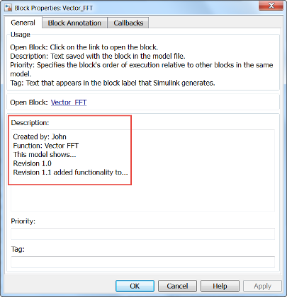
The block comments appear as headers in the generated HDL code.
-- Simulink subsystem description for vector_fft_implementation_example/Vector_FFT:-- Created by: John
--
-- Function: Vector FFT
-- This model shows...
-- Revision 1.0
-- Revision 1.1 added functionality to...
LIBRARY IEEE;
USE IEEE.std_logic_1164.ALL;
USE IEEE.numeric_std.ALL;
ENTITY Vector_FFT IS
See Also
Functions
Modeling Guidelines
- Guidelines for Model Setup and Checking Model Compatibility | Modeling with Simulink, Stateflow, and MATLAB Function Blocks