Use Simulink Templates for HDL Code Generation - MATLAB & Simulink (original) (raw)
HDL Coder™ model templates in Simulink® provide you with design patterns and best practices for models intended for HDL code generation. Models you create from one of the HDL Coder model templates have their configuration parameters and solver settings set up for HDL code generation. To configure an existing model for HDL code generation, use hdlsetup.
Create Model Using HDL Coder Model Template
To model hardware for efficient HDL code generation, create a model using an HDL Coder model template.
- Open the Simulink Start Page. In the MATLAB® Home tab, select the Simulink button. Alternatively, at the command line, enter:
- In the HDL Coder section, you see templates that are preconfigured for HDL code generation. Selecting the template opens a blank model in the Simulink Editor. To save the model, select > .
- To open the Simulink Library Browser and then open the HDL Coder Block Library, select the Library Browser button in the Simulink Editor. Alternatively, at the command line, enter
To filter the Simulink Library Browser to show the block libraries that support HDL code generation, use thehdllibfunction:
HDL Coder Model Templates
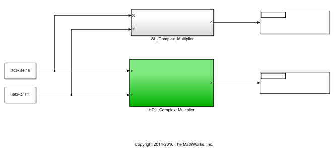
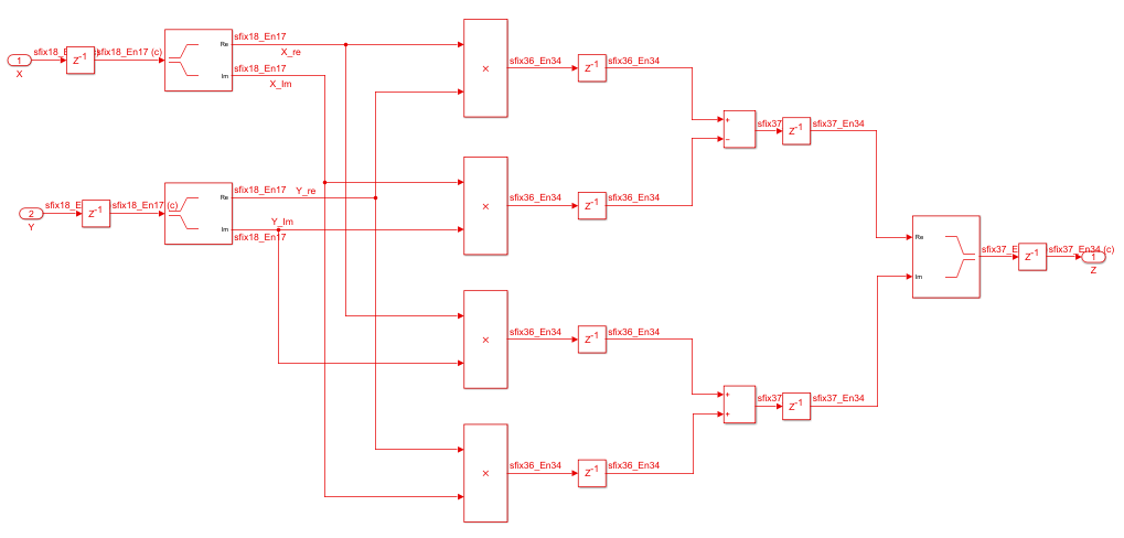
Complex Multiplier
The Complex Multiplier template shows how to model a complex multiplier-accumulator and manually pipeline the intermediate stages. The hardware implementation of complex multiplication uses four multipliers and two adders.
The template applies the following best practices:
- In the Configuration Parameters dialog box, in > , Reset type is set to
Synchronous. - To improve speed, Delay blocks, which map to registers in hardware, are at the inputs and outputs of the multipliers and adders.
- To support the output data of a full-precision complex multiplier, the output data word length is manually specified to be (
operandwordlength* 2) + 1.
For example, in the template, the operand word length is 18, and the output word length is 37.
MATLAB Arithmetic
The MATLAB Arithmetic template contains MATLAB arithmetic operations that infer DSP48s in hardware.
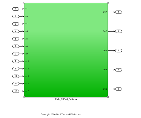
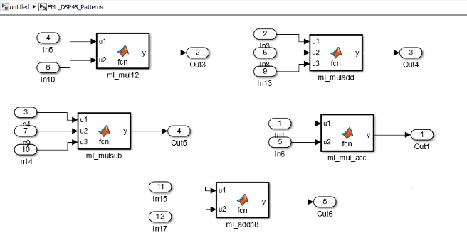
For example, the ml_mul_acc MATLAB Function block shows how to write a multiply-accumulate operation in MATLAB. hdlfimath applies fixed-point math settings for HDL code generation.
function y = fcn(u1, u2)
% design of a 6x6 multipler % same reset on inputs and outputs % followed by an adder
nt = numerictype(0,6,0); nt2 = numerictype(0,12,0); fm = hdlfimath;
persistent u1_reg u2_reg mul_reg add_reg; if isempty(u1_reg) u1_reg = fi(0, nt, fm); u2_reg = fi(0, nt, fm); mul_reg = fi(0, nt2, fm); add_reg = fi(0, nt2, fm); end
mul = mul_reg; mul_reg = u1_reg * u2_reg; add = add_reg; add_reg(:) = mul+add; u1_reg = u1; u2_reg = u2;
y = add;
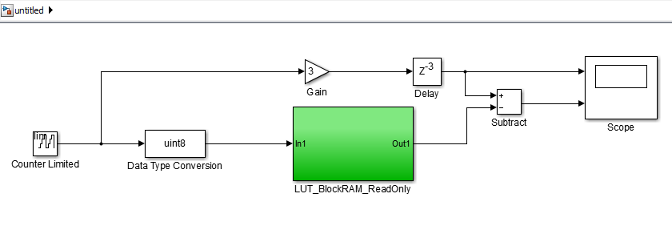
ROM
The ROM template is a design pattern that maps to a ROM in hardware.
The template applies the following best practices:
- At the output of the lookup table, there is a Delay block with
ResetType=none. - The lookup table is structured such that the spacing between breakpoints is a power of two.
Using table dimensions that are a power of two enables HDL Coder to generate shift operations instead of division operations. If necessary, pad the table with zeros. - The number of lookup table entries is a power of two. For some synthesis tools, a lookup table that has a power-of-two number of entries maps better to ROM. If necessary, pad the table with zeros.

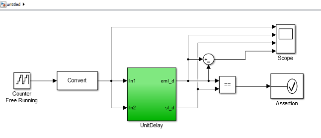
Register
The Register template shows how to model hardware registers:
- In Simulink, using the Delay block.
- In MATLAB, using persistent variables.
This design pattern also shows how to use cast to propagate data types automatically.
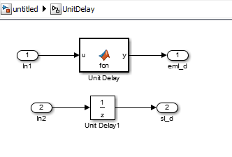
The MATLAB code in the MATLAB Function block uses a persistent variable to model the register.
function y = fcn(u) % Unit delay implementation that maps to a register in hardware
persistent u_d; if isempty(u_d) % defines initial value driven by unit delay at time step 0 u_d = cast(0, 'like', u); end
% return delayed input from last sample time hit y = u_d;
% store the current input u_d = u;
SRL
The SRL template shows how to implement a shift register that maps to an SRL16 in hardware. You can use a similar pattern to map to an SRL32.
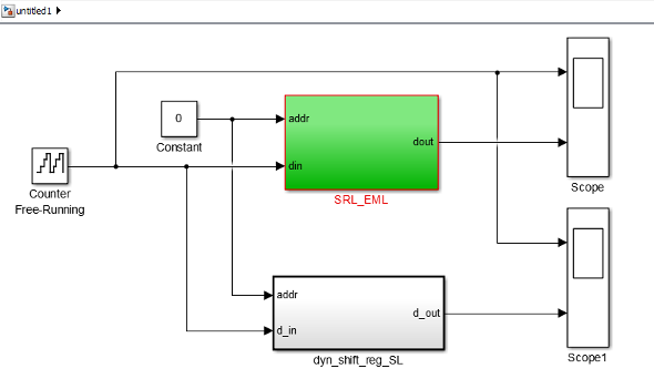
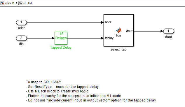
In the shift register subsystem, the Tapped Delay implements the shift operation, and the MATLAB Function, select_tap, implements the output mux.
In select_tap, the zero-based address, addr increments by 1 because MATLAB indices are one-based.
function dout = fcn(addr, tdelay) %#codegen
addr1 = fi(addr+1,0,5,0); dout = tdelay(addr1);
In the generated code, HDL Coder automatically omits the increment because Verilog®, SystemVerilog and VHDL® are zero-based.
The template also applies the following best practices for mapping to an SRL16 in hardware:
- For the Tapped Delay block:
- In the Block Parameters dialog box, Include current input in output vector is not enabled.
- In the HDL Block Properties dialog box, ResetType is set to
none.
- For the Subsystem block, in the HDL Block Properties dialog box,FlattenHierarchy is set to
on.
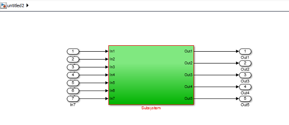
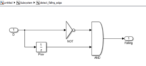
Simulink Hardware Patterns
The Simulink Hardware Patterns template contains design patterns for common hardware operations:
- Serial-to-parallel shift register
- Detect rising edge
- Detect falling edge
- SR latch
- RS latch
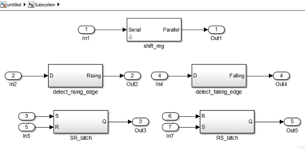
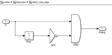
For example, the design patterns for rising edge detection and falling edge detection:
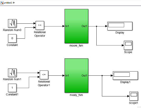
State Machine in MATLAB
The State Machine in MATLAB template shows how to implement Mealy and Moore state machines using theMATLAB Function block.
To learn more about best practices for modeling state machines, see Model a State Machine for HDL and High-Level Synthesis Code Generation.