Create HDL-Compatible Simulink Model - MATLAB & Simulink (original) (raw)
This example illustrates how you can create a Simulink® model for HDL code generation. To create a MATLAB® algorithm compatible for HDL code generation, see Guidelines for Writing MATLAB Code to Generate Efficient HDL and HLS Code.
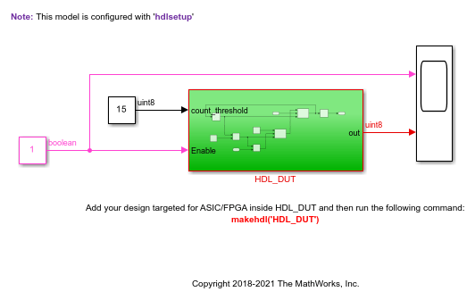
The model is a simple counter algorithm that counts upward and wraps back to zero after it reaches the upper limit that you specify. To open the model directly without performing the steps, see Simple Counter Model.
Use Blank DUT Template
To create a HDL-compatible Simulink model, use the Blank DUT template. The template is preconfigured for HDL code generation by using the hdlsetup function.
- On the MATLAB toolstrip, click the
 button.
 - In the Simulink Start Page, navigate to the HDL Coder section, and then select the Blank DUT template.
- Save the model with the file name
hdlcoder_simple_up_counter.slxin a working folder that is writable.
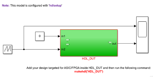
The Blank DUT template has a HDL_DUT subsystem that corresponds to the Design-Under-Test (DUT) for which you generate HDL code. To verify the DUT functionality, the template contains a test bench outside the HDL_DUT subsystem that provides inputs to the DUT and logs output values. See Partition Model into DUT and Test Bench.
Choose Blocks from HDL Coder Library
To design your counter algorithm, use blocks from the HDL Coder Block Library. Blocks in this library are preconfigured for HDL code generation. To filter the Simulink Library Browser to show block libraries that support HDL code generation:
- On the Apps tab, select HDL Coder.
- From the tab, select > .
Alternatively, at the command line, enter hdllib.
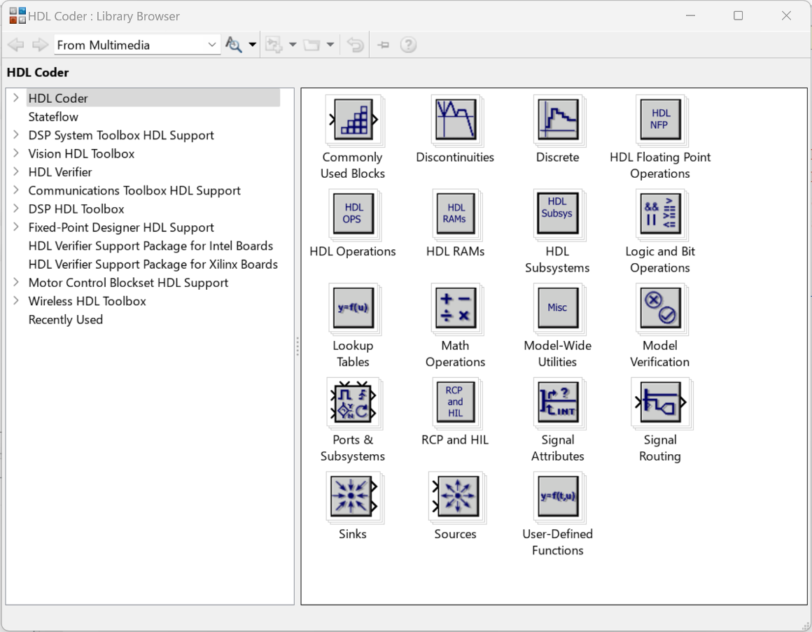
Blocks in the HDL Coder Library are available with Simulink. If you do not have HDL Coder™, you can simulate the blocks in your model, but cannot generate HDL code.
You can find additional HDL-supported blocks in these block libraries:
- DSP System Toolbox HDL Support
- Communications Toolbox HDL Support
- Vision HDL Toolbox
- Wireless HDL Toolbox
To restore the Library Browser to the default view, in the Library Browser, click the  button. Alternatively, at the command line, enter:
Develop Algorithm for DUT
- Double-click the
HDL_DUTsubsystem. Drag blocks from the HDL Coder library to your model. This table lists the blocks to add to your model for designing the counter. To learn about what a block does and to specify its block parameters, double-click the block.Block Library Number of Blocks Block Parameters Constant Sources 2 Constant values: 1 and 0Output data type: uint8 Switch Signal Routing 2 Criteria for passing first input: u2 > Threshold Delay Discrete 2 Delay length: 1 Sum Math Operations 1 Accumulator data type: Inherit: Same as first input Relational Operator Logic and Bit Operations 1 Relational operator: > - Rename the input ports
In1andIn2tocount_thresholdandEnablerespectively. Place the blocks in your model and connect them.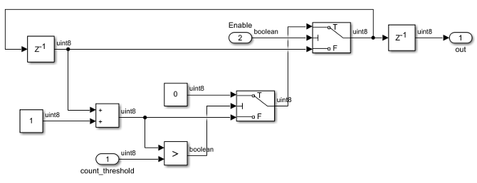
The Enable signal specifies whether the counter counts upward from the previous value. When the Enable signal is logical high, the counter counts up from zero to thecount_threshold value. When the value ofout becomes equal to thecount_threshold value, the counter wraps back to zero and starts counting again. When the Enable signal becomes logical low, the counter holds the previous value.
Create Test Bench for Design
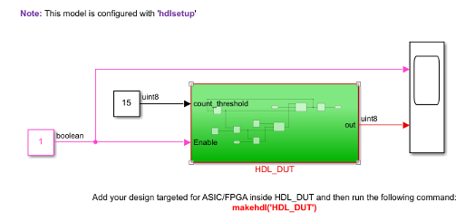
Navigate to the top level of the model and change the input settings.
- Constant block input to
count_threshold: This input indicates the maximum value up to which the counter counts. This example shows how to design a 4-bit up counter. Set the Constant value to15(2^4 - 1), and set theOutput data type touint8.
The output data type of this Constant block then matches the output data type of the Constant blocks inside theHDL_DUTsubsystem. - Counter Free-Running block input to
Enable: Remove the Counter Free-Running block. Replace this block with aConstant block that has a value of1, Output data type set toboolean, and Sample time of1.
See also Create a Simple Model.
The preceding section shows thehdlcoder_simple_up_counter.slx model that you created by following the steps described above. To open the model in MATLAB, click the Open Model button.
Simple Counter Model
Open this model to see a simple counter. The model counts up from zero to a threshold value and then wraps back to zero. The threshold value is set to 15. To change the threshold value, change the value of the input to the count_threshold port. The Enable signal specifies whether the counter counts upward or holds the previous value. A value of 1 indicates that the counter counts upward continuously.
Simulate and Verify Design Functionality
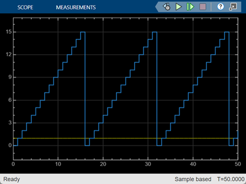
Set the Stop time of the model to 50. Simulate your model by clicking the  button. To see the simulation results, open the Scope block at the top level of your model.
The simulation results display the Enable signal generating a constant value of 1. The out signal counts from 0 to 15, wraps back to zero, and then counts up again.
Generate HDL Code from Simulink Model
Before you generate HDL code, you can verify that the model settings are compatible for HDL code generation. The counter model used in this example is compatible for HDL code generation. To verify and update your model for HDL compatibility, use the HDL Code Advisor. See Check HDL Compatibility of Simulink Model Using HDL Code Advisor.
See Generate HDL Code from Simulink Model.
See Also
hdllib | checkhdl | hdlsetup | hdlcodeadvisor