Introduction to Stateflow HDL Code Generation - MATLAB & Simulink (original) (raw)
Stateflow® charts describe complex system behavior by using hierarchical finite state machine (FSM) theory, flow diagram notation, and state transition diagrams.
You can use a Stateflow chart to model a finite state machine or complex control algorithm for an ASIC or FPGA. When the model meets the design requirements, you then generate VHDL®, Verilog® or SystemVerilog code that implements the design. You can simulate and synthesize the generated HDL code by using industry-standard tools, and then map your system designs on FPGAs and ASICs. For more information on how to generate HDL code for finite state machines, see Generate HDL for Mealy and Moore Finite State Machines.
Generate HDL Code from Stateflow Charts
This example shows how to generate HDL code for a subsystem that includes Stateflow charts.
Open Model
The model hdlcodercfir implements a pipelined, configurable, and symmetric FIR filter.
To open the model, run this command in the MATLAB Command Window:
open_system("hdlcodercfir");
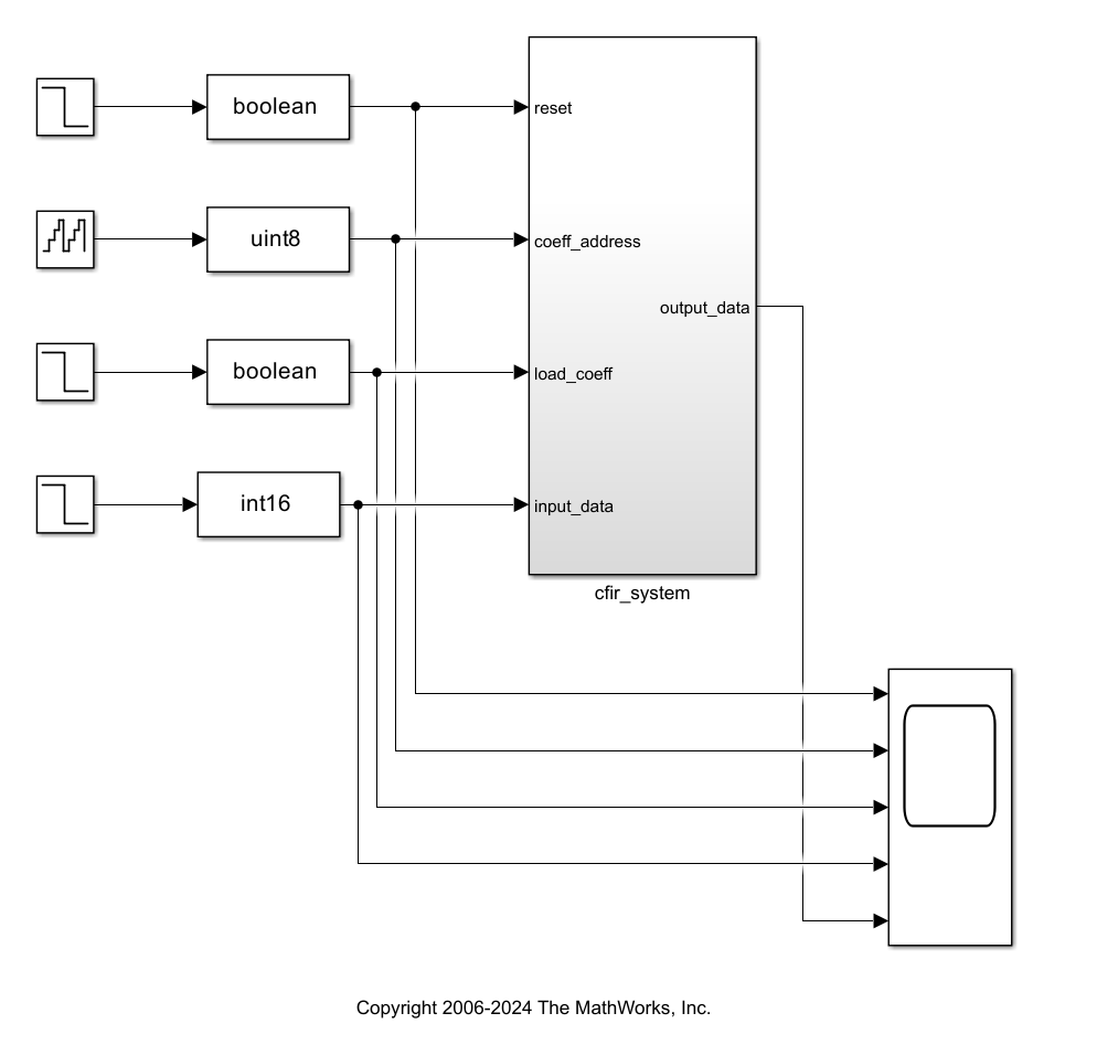
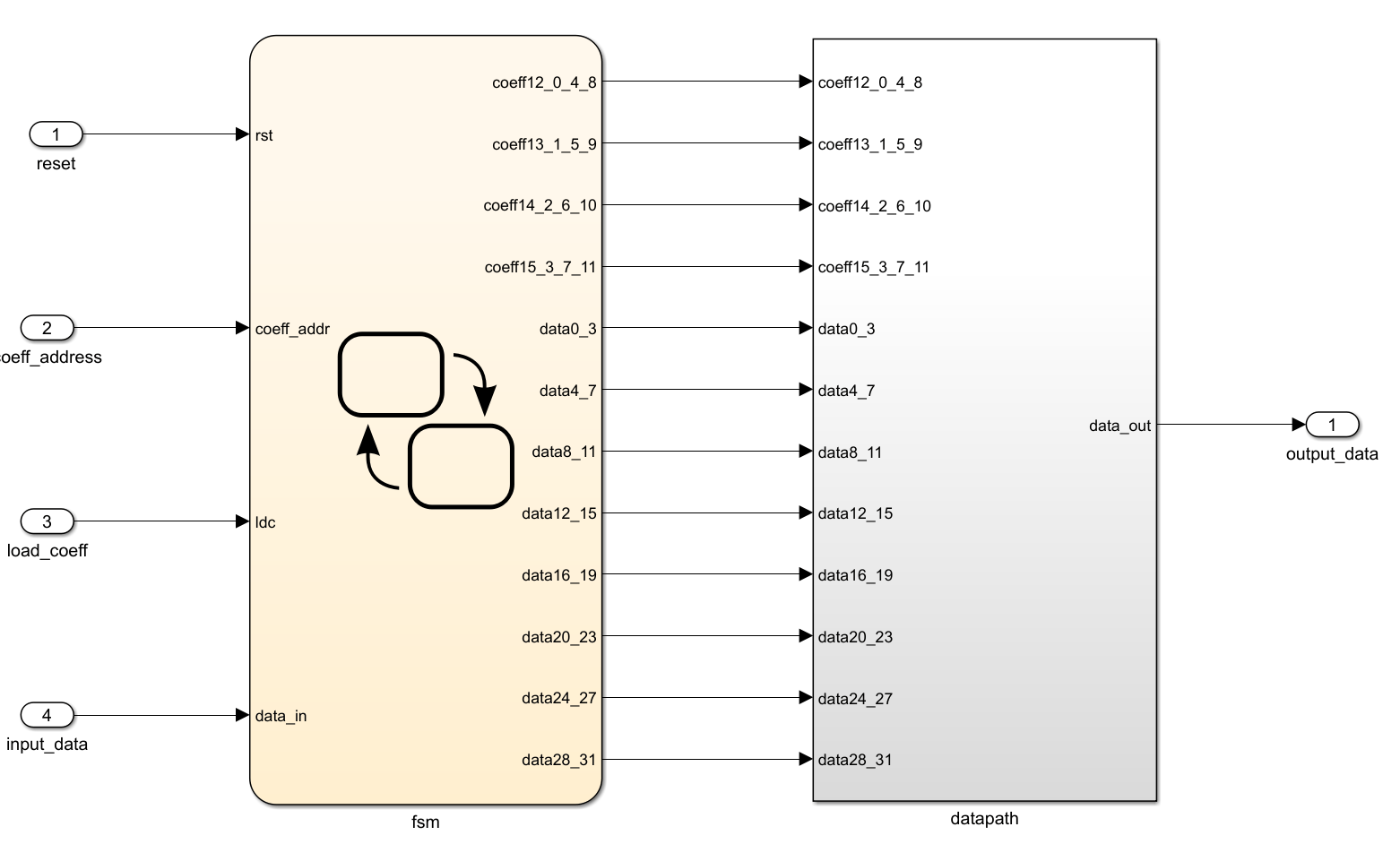
A Stateflow chart inside the subsystem controls the resource sharing. To open the subsystem, double-click cfir_system.
Configure Chart Properties
1. To open the Stateflow chart, double-click the fsm chart.
2. On the Simulink Toolstrip, on the Modeling tab, click Chart Properties. To generate HDL code, the Action Language property must be C and the State Machine Type property must be Classic.
3. Enable the Execute (enter) chart at initialization property to update the chart immediately after chart initialization. You cannot perform arithmetic in initialization actions because reset actions are unable to manage the latency associated with combinatorial logic. For more information, see Execution of a Chart at Initialization (Stateflow).
4. Select the Initialize outputs every time chart wakes up property. If you clear this property, the generated HDL code includes an additional register for the state machine output values.
5. Click OK.
Generate HDL Code for Subsystem
Before you generate HDL code, enable traceability in the generated code. When you enable traceability, the code generator produces code with bi-directional traceability. You can view the generated code in the HDL Code pane or in the HTML code generation report. You can use the traceable generated code to verify that the generated code meets the design requirements. To enable the traceability in the generated code:
1. In the Apps tab, click HDL Coder.
2. In the HDL Code tab, click Settings.
3. In the HDL Code Generation > Report pane, select the Generate traceability report parameter. By default, the code generator uses the line-level style to generate the traceability. You can customize the style by changing the Traceability style parameter.
4. Click OK.
5. To generate HDL code for the subsystem that contains the Stateflow chart, on the HDL Code tab, click Generate HDL Code.
6. View the generated code in the HTML report or the HDL Code pane. The HTML report contains other reports that provide insights about the generated code.
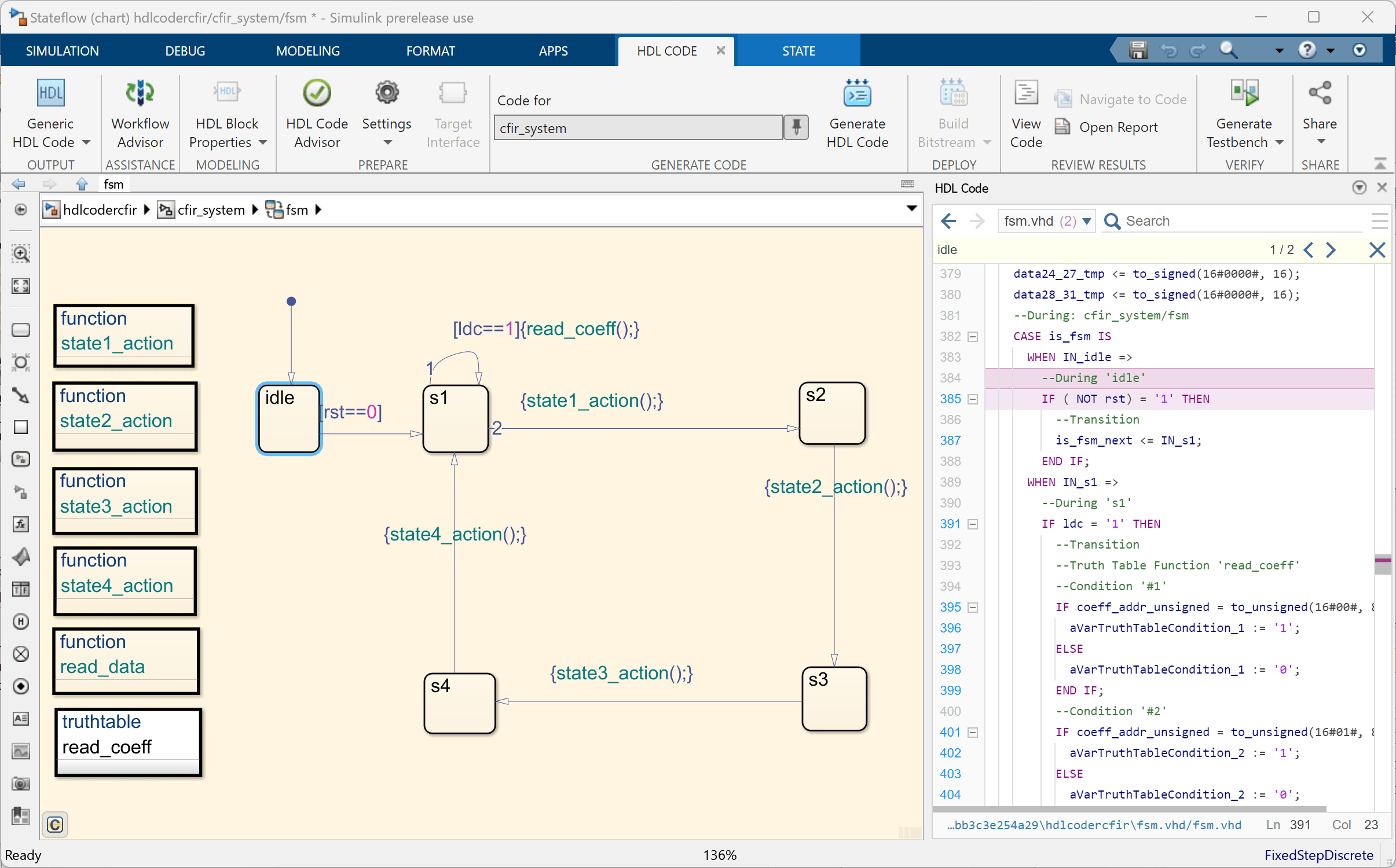
You can use the HDL Code pane to navigate and trace the generated code for corresponding Stateflow elements. For example, when you select the idle state in the Stateflow chart, HDL Coder highlights the generated code in the HDL Code pane.
Generate Test Bench for Subsystem
To generate a test bench for the cfir_system subsystem, on the HDL Code tab, click Generate Testbench.
Latency of Stateflow Blocks
When optimizations or block implementations introduce latency in a model, the total latency associated with a Stateflow block combines at the output of the block. You can view the detailed information on blocks that introduce latencies due to optimization requests or the implementation of certain block architectures in the Delay Balancing optimization report. For more information, see Understand Delay Balancing in HDL Coder.
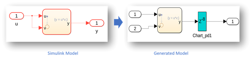
For example, the Stateflow Chart shown in this figure has the HDL block propertyDistributedPipelining enabled and the HDL block propertyOutputPipeline set to 8. Because of these HDL optimizations, HDL Coder™ introduces eight cycles of latency to the block. To view detailed information on latency introduced due to the optimizations, generate the optimization report for your model and view the Delay Balancing report.
Optimizations for Stateflow Blocks
You can apply these optimizations to Stateflow blocks to optimize the generated code for speed and area:
- Clock-Rate Pipelining
- Understand Delay Balancing in HDL Coder
- Resource Sharing
- Adaptive Pipelining
- Distributed Pipelining
- Critical Path Estimation
- InputPipeline
- OutputPipeline
- ConstrainedOutputPipeline
Limitations
HDL code generation does not support Stateflow blocks that contain messages.
Location of Charts in the Model
To generate HDL code from a chart, the chart must be part of a Simulink® subsystem. If the chart for which you want to generate code is at the root level of the model, embed the chart in a subsystem and connect the relevant signals to the subsystem inputs and outputs.
Data Types
The code generator supports these MATLAB® data types in charts:
- Signed and unsigned integer
- Fixed point
- Native floating point
- Boolean
- Enumeration
Note
The code generator does not support:
- Multidimensional arrays for data types assigned to ports. Port data types must be either scalar or vector
- Native floating point data types in conditionally triggered or enabled Stateflow charts or Moore charts.
If you use single and double data types, HDL Coder generates real data types in the HDL code. You can simulate and verify the code by using third-party simulators such as ModelSim™.
Imported Code
Charts must be entirely self-contained. These restrictions apply:
- Do not call MATLAB functions other than
minormax. - Do not use a MATLAB System object™ in a Chart block.
- Do not use MATLAB workspace data.
- Do not call C math functions. HDL does not have a counterpart to the C math library.
- If the Enable C-bit operations property is cleared, do not use the exponentiation operator (
^). The exponentiation operator uses C math library functionpow. - Do not include custom code. The code generator ignores information on the > pane in the Configuration Parameters dialog box.
- Do not use Data Store Memory blocks to share data between charts. HDL Coder does not map global data to HDL because HDL does not support global data.
Vector of Tunable Parameters
HDL code generation does not support using vectors of tunable parameters as data types for Chart blocks.
Input and Output Events
HDL Coder supports the use of input and output events with Stateflow charts, with these constraints:
- You can define and use only one input event per Stateflow chart. There is no restriction on the number of output events.
- The code generator does not support HDL code generation for charts that have a single input event and nonzero initial values on the output ports.
- All input and output events must be edge-triggered.
For detailed information about input and output events, see Activate a Stateflow Chart by Sending Input Events (Stateflow) and Activate a Simulink Block by Sending Output Events (Stateflow).
Messages
Stateflow messages are not supported for HDL code generation.
Loops
Other than for-loops, do not explicitly use loops in a chart intended for HDL code generation. Observe these restrictions for for-loops:
- The data type of the loop counter variable must be
int32. - HDL Coder supports only constant-bounded loops.
The for-loop example, sf_for, shows a design pattern for a for-loop that uses a graphical function.
Additional Limitations
Because HDL code does not support some features of general-purpose sequential programming language, Stateflow charts must meet these additional restrictions:
- You must make separate copies for each instance of an atomic subchart. For more information, see Convert an Atomic Subchart to a Normal Subchart (Stateflow).
- Do not generate HDL code for Simulink Function blocks.
- Do not define local events in charts.
- Do not use these implicit events:
enterexitchange
If you use temporal logic, you can use these implicit events:wakeuptick
- Do not use recursion through graphical functions. HDL Coder does not support recursion.
- Avoid unstructured code. Although charts allow unstructured code in the form of transition flow diagrams and graphical functions, this usage results in
gotostatements and multiple function return statements. HDL does not supportgotostatements or multiple function return statements. - If the Initialize Outputs Every Time Chart Wakes Up chart option is cleared, do not read from output ports.
- Do not use Data Store Memory objects.
- Do not use pointer (
&) or indirection (*) operators. See Pointer and Address Operations (Stateflow). - If a chart returns a run-time overflow error during simulation, it is possible to disable data range error checking and generate HDL code for the chart. In this case, some results obtained from the generated HDL code may not be bit-true to the results from the simulation. The recommended practice is to enable the overflow checking and eliminate overflow conditions in the model.
See Also
State Transition Table (Stateflow) | Truth Table (Stateflow) | Sequence Viewer (Stateflow)