insertion loss (original) (raw)
Definition: power losses due to insertion of a device
Alternative term: attenuation
Categories:  general optics,
  fiber optics and waveguides
Related: fiber splicesfiber connectorsdecibelreturn lossoptical time-domain reflectometers
Units: %, dB
Formula symbol: IL
Page views in 12 months: 986
DOI: 10.61835/yma Cite the article: BibTex BibLaTex plain textHTML Link to this page! LinkedIn
Content quality and neutrality are maintained according to our editorial policy.
📦 For purchasing fiber couplers, use the RP Photonics Buyer's Guide — an expert-curated directory for finding all relevant suppliers, which also offers advanced purchasing assistance.
Contents
Examples of Insertion Loss
If an optical device is inserted into a setup, some of the optical power may be lost in the device or at optical interfaces. Some examples:
- A fiber connector, a mechanical splice or a fusion splice may be used to connect two fibers, instead of having a single continuous fiber. Some of the optical power will be lost due to non-perfect interfaces, not exactly matching effective mode areas or similar factors.
- A large amount of insertion loss may be intentionally inserted in the form of a fiber-optic attenuator.
- A Faraday isolator is inserted after the output of a laser to prevent it against back-reflections. Some power is lost at imperfect anti-reflection coatings of the isolator and possibly by parasitic absorption or scattering in the optical elements.
The insertion loss (or attenuation) is usually specified in decibels, calculated as 10 times the logarithm of base 10 of the ratio of input and output powers. For fiber connectors, for example, it is often of the order of 0.5 dB. High-quality fusion splices may reach values like 0.02 dB.
For high-power devices, a high insertion loss is often unwanted not only due to the power loss but also because of possibly strong heating effects resulting from absorbed light.
Measuring Insertion Loss
A convenient method for measuring insertion loss is optical time-domain reflectometry. With that, the insertion loss of multiple optical elements along a fiber can be measured separately.
For use mainly in optical fiber communications, there are optical loss testers with which insertion losses can be quite conveniently measured.
Frequently Asked Questions
This FAQ section was generated with AI based on the article content and has been reviewed by the article’s author (RP).
What is insertion loss?
How is insertion loss quantified?
Insertion loss is usually specified in decibels (dB). It is calculated as 10 times the base-10 logarithm of the ratio of the input power to the output power.
What are typical insertion loss values for fiber optic components?
A typical fiber connector has an insertion loss of around 0.5 dB. A high-quality fusion splice can have a much lower loss, around 0.02 dB.
How can insertion loss be measured?
Why is high insertion loss a problem in high-power systems?
In high-power devices, a high insertion loss is unwanted not only because of the power reduction but also because the absorbed light can cause significant and potentially damaging heating of the component.
Suppliers
Sponsored content: The RP Photonics Buyer's Guide contains 101 suppliers for fiber couplers. Among them:

⚙ hardware

Schäfter+Kirchhoff's high precision fiber couplers (fiber port) are optimized for high pointing stability and long-term stability. They provide efficient coupling of collimated laser radiation into single-mode and PM fiber cables. They are available as 60SMS and 60SMF version with a large variety of focal lengths and different optics including aspheres, achromats and apochromats. Well-proven in the lab and in industrial fiber coupling sets.

⚙ hardware
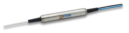
CSRAYZER’s polarization-maintaining filter or fused coupler series products are used to split inputs from a polarization-maintaining optical fiber according to the given coupling ratio. They are widely used in fiber lasers, optical fiber amplifiers, optical fiber communications and fiber sensors, having compact dimensions, low insertion loss, low polarization dependent loss and high stability, and the ability to work under different temperature conditions.

⚙ hardware

The G&H line of HI REL fused fiber optic components are available in PM and SM form. They are deployed in environments such as undersea and space where the costs of component replacement are prohibitive and reliability is of premier concern.
G&H is established as a preferred supplier of these components to most major undersea telecommunications equipment manufacturers. Our HI REL capability is built upon the foundation of an extended history of also manufacturing very reliable components for land-based (or terrestrial) systems in volume.

⚙ hardware

TOPTICA´s COOL patent pending fiber coupling concept is new, because it does not use any mechanical micro adjustable parts, which normally are the first to move due to thermal or mechanical influences.All major optical components are solidly mounted and the optical micro alignment is unsusceptible to mechanical and thermal distortions or translations.

⚙ hardware
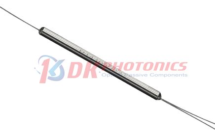
DK Photonics uses a unique fusing technique and polarization-maintaining fibers to fabricate the polarization maintaining fused coupler (PMC). The coupling ratio can be selected according to the customer’s request. It features low excess loss, small size and high polarization extinction ratio. PMC is widely used for optical sensors and optical gyros.
Questions and Comments from Users
Here you can submit questions and comments. As far as they get accepted by the author, they will appear above this paragraph together with the author’s answer. The author will decide on acceptance based on certain criteria. Essentially, the issue must be of sufficiently broad interest.
Please do not enter personal data here. (See also our privacy declaration.) If you wish to receive personal feedback or consultancy from the author, please contact him, e.g. via e-mail.
By submitting the information, you give your consent to the potential publication of your inputs on our website according to our rules. (If you later retract your consent, we will delete those inputs.) As your inputs are first reviewed by the author, they may be published with some delay.