Multiplexer Design using Verilog HDL (original) (raw)
Last Updated : 15 Jul, 2025
The Verilog Hardware Description Language is an important language in the world of digital design where electronic systems are modeled using it. It provides a way of describing and simulating both the behavior and structure of digital circuits; hence, it is an important tool for engineers in hardware design and verification. Verilog HDL provides for the making of detailed specifications of complex digital systems through its syntax and constructs, hence assisting in its development and testing.
In this article, we are discussing Multiplexer Design. Below mentioned is the article in which we are going to discuss the problem.
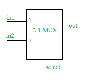
Design of a 2:1 MUX using Verilog Hardware Description Language along with Testbench.
**Concepts
A multiplexer is a combinational type of digital circuit that is used to transfer one of the available input lines to a single output and, which input has to be transferred to the output will be decided by the state(logic 0 or logic 1) of the select line signal. 2:1 Multiplexer has two inputs, one select line (to select one of the two inputs), and a single output.
**Truth Table
| select | out |
|---|---|
| 0 | in1 |
| 1 | in2 |
**Verilog HDL code of 2:1 MUX
**Design
// define a module for the design module mux2_1(in1, in2, select, out);
// define input port input in1, in2, select;
// define the output port output out;
// assign one of the inputs to the output based upon select line input assign out = select ? in2 : in1; endmodule :mux2_1
**Testbench
module test; reg in1, in2, select; wire out;
// design under test mux2_1 mux(.in1(in1), .in2(in2), .select(select), .out(out));
// list the input to the design initial begin in1=1'b0;in2=1'b0;select=1'b0; #2 in1=1'b1; #2 select=1'b1; #2 in2=1'b1; #2 $stop(); end
// monitor the output whenever any of the input changes initial begin $monitor("time=%0d, input1=%b, input2=%b, select line=%b, output=%b", $time, in1, in2, select, out); end endmodule :test
**Expected Output
time=0, input1=0, input2=0, select line=0, out=0 time=2, input1=1, input2=0, select line=0, out=1 time=4, input1=1, input2=0, select line=1, out=0 time=6, input1=1, input2=1, select line=1, out=1
Gate level /Structural Modeling
module mux4x1_gate_level( input a, input b, input c, input d, input s0, input s1, output y );
wire n1, n2, n3, n4, n5, n6;

not (n1, s1);
not (n2, s0);
and (n3, a, n1, n2);
and (n4, b, n1, s0);
and (n5, c, s1, n2);
and (n6, d, s1, s0);
or (y, n3, n4, n5, n6);
endmodule
Dataflow Modelling
module mux4x1(
input s0,
input s1,
input a,
input b,
input c,
input d,
output y
);
assign y = (a & (s1) & (s0)) |(b & (s1) & s0) |(c & s1 & (s0)) |(d & s1 & s0);
endmodule
What is Verilog HDL?
Verilog HDL is a high-level hardware description language that, through its modeling, simulation, and designing features, finds wide applications for digital circuits. It allows the engineer to describe both structure and behavior of digital systems even from logic gates, flip-flops, and multiplexers. Being an IEEE-standardized language (IEEE 1364), Verilog finds very important application in design, verification, and synthesis related to integrated circuits.
Verilog HDL allows designers to describe digital circuits using text formats, which in turn enable easier simulation, timing analysis, and subsequent physical implementation of such hardware. It finds extensive applications at the RTL for complex electronic systems designs.
What is Multiplexer?
MUX refers to a kind of digital circuitry where one out of several incoming signals is selected and forwarded towards one output line. This is mainly a sort of data selector or switch in which the signal input to be selected is determined by control signals. Multiplexers are some of the fundamental gadgets in the digital circuits of today's time factor owing to their efficiency in the routing and selection of data.
Thus, a MUX is a device with the following properties: selection lines represent control signals that select input to go through to output; several input lines where only one is relayed to the output line depending on those selection lines; an output line, the single line where the selected input signal is sent to.
Uses of Multiplexer
- **Data Routing: Data is routed to various destinations with the use of multiplexers for better performance of the system.
- **Demultiplexing: It splits a single data signal into multiple output signals.
- **Logic Function Implementation: It implements **AND, OR, XOR logic functions, and many more.
- **Digital Systems Design: Used in designing complex systems such as microprocessors and memory units.
- **Signal Selection: It allows for the selection of one signal out of multiple sources of data so that effective processing can be achieved.
- **Resource Sharing: More than one device can share a single resource, like a data bus.
How to Connect Multiplexers?
- **Cascading: Output of one multiplexer connected to the input of the other. The idea here is that with more and more MUXs cascading, you will be able to select from an even larger number of inputs.
- **Parallel Connection: Several multiplexers connected in parallel handle multiple sets of inputs. Thus it simultaneously selects more data sources.
- **Tree Structure: Arrange multiplexers in a tree-like or hierarchical fashion. At this structure, large numbers of inputs are dealt with comfortably, and routing of data within it is less painful.
- **Hierarchical Approach: Construct larger multiplexers using smaller ones. For instance, using three 2-to-1 multiplexers, an 8-to-1 multiplexer can be realized, with outputs from the smaller MUXs feeding into a larger one and selection lines configured appropriately.
Advantages of Multiplexers
- **Efficient Data Routing: The use of multiplexers provides that several data signals can be routed onto and using one channel owing to the fact that they optimize resource usage.
- **Component Count Reduction: Fewer components will be involved in the selection and routing of the data, hence designing is simpler.
- **Flexibility: They have flexibility and can thus easily be configured for different applications.
- **Scalability: Multiplexers are easily scalable in that with the combination of many units, the input handling capability increases, hence increasing design flexibility.
Disadvantages of Multiplexers
- **Increasingly Complex: Cascading several multiplexers and complicated structures make the circuits more complex; designing is increasingly difficult.
- **Latency in Performance: Since the selection operation would be carried out by a multiplexer, delays would be caused and affect the performance of the system-particularly high-speed systems.
- **It can draw power: these are not necessarily drawing power; however, in many usages, the rate of power consumption can increase.
- **Propagation delay: because of the time delays that may take place in signal transmission on using a number of MUX, the overall performance of the circuit deteriorates.
Conclusion
Verilog HDL is important in the design and modeling of digital systems, thus helping engineers create elaborate and exacting circuits. Multiplexers form part of these designs, providing an effective system of data management and routing versatility that is fundamental to both simple and advanced systems. Understanding how to combine multiplexers-through cascading, parallel connections, or hierarchical structures-helps engineers optimize circuit layouts and performance.
Drawbacks of multiplexers are, for example, increased design complexity and propagation delays. Successful digital circuit design will have to balance these. As the technology will keep on evolving, so will Verilog find its place-along with multiplexers-in devising ingenious electronic solutions and increasing performance further in hardware.