Long tethers provide high-force coupling of the Dam1 ring to shortening microtubules (original) (raw)
Abstract
Microtubule kinetochore attachments are essential for accurate mitosis, but how these force-generating connections move chromosomes remains poorly understood. Processive motion at shortening microtubule ends can be reconstituted in vitro using microbeads conjugated to the budding yeast kinetochore protein Dam1, which forms microtubule-encircling rings. Here, we report that, when Dam1 is linked to a bead cargo by elongated protein tethers, the maximum force transmitted from a disassembling microtubule increases sixfold compared with a short tether. We interpret this significant improvement with a theory that considers the geometry and mechanics of the microtubule–ring–bead system. Our results show the importance of fibrillar links in tethering microtubule ends to cargo: fibrils enable the cargo to align coaxially with the microtubule, thereby increasing the stability of attachment and the mechanical work that it can do. The force-transducing characteristics of fibril-tethered Dam1 are similar to the analogous properties of purified yeast kinetochores, suggesting that a tethered Dam1 ring comprises the main force-bearing unit of the native attachment.
Keywords: laser tweezers, mathematical modeling, microtubule depolymerization, anaphase, forced walk
Anaphase motions of mitotic chromosomes are slow, and therefore, little force (∼0.1 pN) is required to drive them against viscous drag (1). Spindle microtubules (MTs) are, however, capable of exerting much greater forces (>45 pN/MT) (2), probably to overcome segregation problems like the entanglement of chromosome arms or erroneous MT attachments. Because yeast chromosomes can move poleward without motor enzymes, depolymerizing MTs may provide the major drive for chromosome motion (3, 4). Dynamic MT ends exert these forces while harnessed to chromosomes by kinetochores, which contain >100 different proteins (5). When conjugated to microbeads, several kinetochore proteins can sustain processive motions at the ends of dynamic MTs (reviewed in ref. 6), but only a few have so far been reported to form force-transducing attachments (7–11). The average force that these proteins captured from MT disassembly was <5 pN. Thus, the links that can harness the large MT depolymerization force and the biophysical requirements for such a coupling mechanism remain poorly understood.
In this context, the multisubunit Dam1 protein complex of Saccharomyces cerevisiae is particularly interesting, because it is essential for chromosome segregation and thought to play a major role in coupling MTs to kinetochores in an end-on configuration (Fig. 1_A_) (4, 12). Recent structural work suggests that such a configuration is facilitated by elongated tethers that reach from Dam1 to the kinetochore hub (13). Purified Dam1 complexes spontaneously assemble in vitro into MT-encircling rings that move processively with disassembling MT ends (14, 15). Moreover, Dam1 conjugated to the surface of a microbead can form load-bearing attachments. Two studies have reported that Dam1 can sustain 2–3 pN on average when situated near the end of a depolymerizing MT (7, 8). These findings and others have led to different models of Dam1-dependent coupling. In one, the Dam1 ring was described as a loosely bound coupler that diffused quickly, and the low measured force was suggested to reflect the low depolymerization force captured by the Dam1 ring (16). The other model, proposed by our group, posited that a Dam1 ring was a tightly bound coupler, showing negligible diffusion, which moved with the end of a shortening MT by a diffusion-free forced-walk mechanism (17). Importantly, the forced-walk model predicts that the Dam1 ring can capture up to 30 pN force from the depolymerization of one MT (8).
Fig. 1.

Use of elongated protein fibrils to tether Dam1 to beads. (A) Schematic of an end-on kinetochore–MT connection with a Dam1 ring tethered to the kinetochore central hub. (B) Lateral attachment of a Dam1-coated bead to an MT in vitro (roughly to scale). Soluble Dam1 subunits are used to promote completion of the full Dam1 ring. (C) Chemical steps involved in Dam1 conjugation to the bead using the 100-nm-long CC tether or directly to the surface with a heterobifunctional cross-linker and anti-GFP IgG.
We have suggested that the small forces recorded in our previous studies resulted from mechanically inefficient coupling between the ring and its bead cargo. Indeed, previously, the bead was coupled laterally to the MT-encircling ring (Fig. 1_B_). Such a geometry should decrease the useful work that a ring-coupled MT can perform, because in this configuration, only a fraction of the MT depolymerization force is transmitted into useful work for moving cargo (8, 18). In contrast, the configuration found in vivo, where the load aligns coaxially with the MT, should be mechanically optimal (Fig. 1_A_). Here, we use advanced laser trapping and single-molecule approaches as well as mathematical modeling to ask whether attaching a bead to Dam1 in an end-on manner improves the coupling and increases the measured force from MT depolymerization.
Results
Fibrillar Tethers Significantly Enhance Force Transduction by the Dam1 Ring.
To suspend Dam1 complexes away from the bead’s surface, we conjugated Dam1 heterodecamers to a bead with 100-nm tethers made from a coiled coil (CC) derived from rat cardiac myosin 2. This protein is not relevant to normal kinetochore function, and therefore, its direct contribution to the MT coupling is not an issue. All native cysteines in this CC were changed to serines, and a unique cysteine was introduced at the C terminus of the CC to allow orientation-specific conjugation with amine-coated beads (Materials and Methods and Fig. 1_C_). To link this tether to Dam1, we also engineered a GFP binding protein (GBP) to the N terminus of the CC (19). This tether bound to Dam1 with an N-terminal GFP fusion, an allele that behaved like untagged Dam1 in both structural and functional tests (Fig. S1 A–C). The result was a specific high-density coat of tethered Dam1 on the bead (Fig. S1_D_). Based on the GFP fluorescence intensity of the beads, we estimated that up to seven CC tethers could simultaneously contact the end of an attached MT (Fig. S1_E_). GFP-Dam1 was also conjugated by a similar chemistry but without the CC tether to make control beads with much shorter tethers of <4 nm (Fig. 1_C_).
The motilities of these two kinds of beads were examined with the previously developed segmented MT assay (Fig. 2_A_) (18). After assembling the reversibly stabilized MTs, beads were added to the experimental motility chambers and allowed to associate with the MTs. Soluble Dam1 was introduced to promote closure of any rings initiated by the bead-conjugated Dam1 (Fig. 1_B_ and Fig. S1_E_). MT depolymerization was then triggered, and we determined the fraction of processively moving beads, their speeds, and the distances that they traveled (Fig. 2 B and C). Both the control and CC-tethered Dam1 beads tracked shortening MT ends such as in previous work, where Dam1 was conjugated directly to the bead’s surface (Fig. S1_C_) (8, 15). The lack of difference between these beads suggests that the mode of tethering does not affect Dam1 motion when the load is light. [With no trap, the only load on the bead was viscous drag (<0.01 pN).]
Fig. 2.

Motility and force transduction by CC-tethered beads. (A) Schematic of our motility assay. A Dam1 bead binds laterally to a segmented MT, which is attached to the coverslip at its minus end and carries a photodestructible stabilizing cap on its plus end. (B) Kymograph of a Dam1 bead moving with MT disassembly. (Scale bar: 5 μm.) (C) Motilities of beads coated with Dam1 by antibodies (control) or CC tethers are similar; error bars in all figures correspond to SEM unless stated otherwise. (D) Schematic of the stationary trap assay to measure force. (E) Examples of unprocessed quadrant photodiode signals recorded with either control or CC-tethered Dam1 beads (trap stiffness = 0.03 and 0.13 pN/nm, respectively). Amplitude of the force signal with CC tether is larger and the bead pauses longer before the detachment. (F) Quantification of force amplitude measured in a stationary trap. Whiskers show minimum to maximum; the box is 25–75%, and + shows the average.
To examine whether tethered beads could carry a bigger load than control beads, we measured how MT-generated forces displaced each kind of bead from the center of a stationary laser trap (Fig. 2_D_) (18). Control beads experienced 3.2 ± 0.5 pN MT-generated force before detaching from a shortening MT, similar to the forces reported previously when Dam1 was conjugated directly to the bead’s surface. Much larger forces were recorded, however, with the CC-tethered Dam1; on average, the amplitudes of these force transients showed an approximately threefold increase (8.7 ± 0.7 pN) (Fig. 2 E and F). The largest measured force was 25 pN, and five beads escaped the trap; therefore, the force acting on them was larger. Thus, linking Dam1 to beads by CC tethers significantly increases the amplitude of the measured force.
Mechanical Model for Bead–MT Coupling Shows the Critical Role of Elongated Tethers in Optimizing the Efficiency of This System.
We have used a materials science approach to examine whether the increased load-bearing could be attributed to the altered geometry of the ring–cargo coupling that resulted from the elongated tethers. The biomechanical system, consisting of an MT with flared protofilaments, an MT-encircling ring, and the bead cargo, was mathematized with a finite element method (Fig. 3_A_) using the elastic moduli specified in Table S1 (Materials and Methods). For this in silico assay, the bead was first attached laterally to the MT in an unstrained configuration, and the trap-mimicking force Ftrap was applied at the bead’s center, pulling it away from the MT tip. Calculations showed that this force changed the orientation of the ring and pressed it against the flared protofilaments (Fig. 3_B_). The resulting resistance to ring motion and Ftrap creates a torque, which is compensated by elastic bending of the MT. The sum of all MT axial forces acting on the ring from the protofilaments (FMT) was then roughly proportional to the force applied by the bead, but its amplitude was ∼12 times larger (Fig. 3_C_). These calculations show that, when the bead is attached laterally, FMT acts through a lever arm, decreasing the useful work that the ring-coupled MT can perform (8). If the bead is attached to the ring by elongated tethers, the angle between the MT axis and the line defined by the centers of the ring and the bead can decrease significantly, thereby decreasing the lever arm effect (Fig. 3 D and E). When cargo attachment is end on, the angle is 0°, and Ftrap = FMT (Fig. 3 C and D), producing maximal efficiency for transducing MT depolymerization energy into useful work. We conclude that the larger force observed with CC tether beads (Fig. 2_F_) was likely caused by changes in the geometry that permitted a better cargo alignment.
Fig. 3.

Biomechanics of force transduction by the MT-encircling ring–bead system. (A) System configuration showing the initial position of an unloaded bead that is subsequently subjected to the trapping force Ftrap. (B) Enlarged view shows tilting of the ring under force acting through the bead; the image was generated with ANSYS software. (C) The slope of the calculated relationship between Ftrap and FMT at steady state reflects the lever arm factor. For lateral ring–bead attachment (black symbols), this factor is 12.5, which means that Ftrap applied at the bead’s center can equalize more than 10-fold larger force than the force that acts on the ring from the MT. For end-on attached bead (red symbols), the lever arm factor is one. (D) A drawing of the system configuration for the angle α = 0°, in which the tethered bead is aligned coaxially with the MT. (E) The lever arm factor decreases as the center of the bead cargo moves closer to the MT axis (note that angle-α from A decreases as the alignment of the bead improves).
Improved Force Transmission Correlates with Alignment of the Bead to the MT Axis.
Kinetochores in vivo often transition from a lateral association with the MT wall to an end-on position (20). Thereafter, the load on the kinetochore–MT coupling is directly along the MT axis. To examine this transition in vitro, we devised an experimental assay that allows time for bead repositioning before the bead is challenged with a big load (Materials and Methods). As above, the initial attachment of CC-tethered Dam1 beads was to the lateral MT wall (Fig. 4 A and B, phase I). As the disassembling MT started to pull on the bead (Fig. 4 A and B, phase II), a small constant load of 3.4 ± 0.5 pN was applied using a force clamp to promote bead repositioning to an end-on configuration (Fig. 4 A and B, phase III). After a period of processive motion, the clamp was turned off, and as the MT continued to shorten, the bead was pulled from the center of the now stationary trap (Fig. 4 A and B, phase IV and Movie S1). For example, the bead in Fig. 4_B_ moved under load with the shortening MT for 1.2 µm before the clamp was stopped. The MT then continued to pull on the bead until it detached at 29 pN, our largest recorded force (Fig. S2).
Fig. 4.

Lateral to axial repositioning of the beads. (A) Illustration of a bead repositioning under the two oppositely directed forces that come from the depolymerizing MT and the trap. The force vectors are initially displaced but become aligned after the bead repositions. (B) Force and stage positions vs. time illustrate five experimental phases in one representative experiment. Phase I, laterally attached motionless bead. Phase II, bead is clamped and pulled to the MT plus end. After the stage settles and the clamp force is maintained constant, we trigger MT depolymerization. Phase III, the end of a shortening MT reaches the bead, and the stage moves to maintain constant force (in Right, the yellow arrowheads point to the MT minus end, and the arrows point to a bead moving in a stationary trap). (Scale bar: 3 μm.) Phase IV, we stop the stage and record the bead’s continued motion in the now stationary trap. Phase V, bead detaches from the MT tip and falls back to the trap’s center. (C) Example tracks of motions for CC-tethered beads (phase III). Tracks with increase in the speed are aligned to the center in the time that this change took place (time 0 for blue curves). (D) Average of centered two-phasic traces of the CC-tethered beads tracking the shortening MT end under an approximately constant trapping force of 2.6 ± 0.5 pN (right axis); dotted lines are SDs. (E) The percent of force signals measured in phase IV with amplitude that exceeded the value specified, normalized for different groups of beads. The CC-tethered beads that increased their speed during phase III (blue) showed larger force transients, on average, than the control beads (black, P < 0.05) or the CC-tethered beads that did not change their speed (green, P < 0.07). The maximum forces measured increased 5.8 and 2.6 times, respectively.
To seek evidence for the repositioning of the bead during its motion under the small load, we analyzed the direction and amplitude of forces acting on the ring throughout the experiment. Given the analysis above, we expected that, if the bead moved from lateral to end-on attachment, the lever arm factor should decrease (Fig. 3_C_). This interpretation predicts that, as the bead repositions under the constant load from the force clamp, the load acting on a Dam1 ring should decrease. Because a Dam1 ring moves faster under a smaller load (17, 21), the repositioning should lead to faster ring motion, although the applied trapping load and the solution chemistry are constant (Movie S1). To test this prediction, we analyzed the kinetics of bead motion in the force clamp during phase III of the above experiment (Fig. 4_B_). Only 15% of the control Dam1 beads (n = 20) increased their speed during this phase, but 70% of the CC-tethered beads (n = 26) showed a pronounced increase from 5.3 ± 0.6 to 11 ± 2 μm/min (Fig. 4_C_, blue lines). Their speeds increased under constant trapping force (Fig. 4_D_), strongly suggesting a decrease in the effective load, just as expected for bead repositioning. This conclusion was corroborated by sorting the force results during phase IV based on the pattern of prior bead motion: the CC-tethered beads that did not speed up during phase III did not withstand loads >11 pN, whereas the beads that did increase their speed were able to sustain loads up to 29 pN (Fig. 4_E_). Two of the latter beads escaped the trap, implying movement against a load of 37 pN. The consistency between our experimental data and model predictions strongly suggests that cargo alignment is a significant factor in the force transduction mechanism for MT depolymerization.
Dam1 Binding to the MT Is Strong Enough to Prevent Its Free Diffusion.
The above experiments and calculations highlighted the mechanical aspects of this system, whereas our previous modeling of the energy and dynamics of Dam1 MT–ring coupling emphasized the importance of the affinity between Dam1 and the MT wall (17). A weakly bound Dam1 ring should diffuse well on the MT wall but is predicted to slip easily from the MT end if flared protofilament extensions are lost (e.g., because of some stochastic event). Tightly bound Dam1 could, in principle, sustain the forces that we have measured here, even at a blunt MT end, but it should be unable to diffuse. Published estimates for the diffusion coefficient of Dam1 rings in vitro range over three orders of magnitude (14, 15), whereas recent EM of Dam1 rings has been interpreted to suggest their free diffusion (16). We have, therefore, measured the diffusion of fluorescently labeled oligomers of Dam1 along MTs (Movie S2). We used both a traditional approach to attach taxol-stabilized MTs to coverslips and microfabricated pedestals to elevate the MTs and avoid possible interference between MT-encircling Dam1 complexes and the coverslip surface (Fig. 5_A_). Dam1 monomers diffused at ∼0.1 μm2/s, consistent with information in refs. 15 and 22; diffusion of Dam1 oligomers decreased exponentially with increasing oligomer size (Fig. 5 B–D and Fig. S3). The exponential dependency indicates that Dam1 subunits contribute additively to the oligomer’s MT binding energy, which is expected if each subunit is in direct contact with MT lattice. The diffusion of ring size complexes was undetectably slow, because it was less than 3⋅10−5 μm2/s, the thermal drift of our microscope stage. The same slow diffusion of Dam1 oligomers was seen on MTs suspended between the pedestals, and therefore, we concluded that it was not caused by nonspecific adhesion to the glass surface (Fig. S3_D_). Exponential extrapolation from the data for smaller complexes estimates a ring’s diffusion coefficient at 10−6–10−8 μm2/s (Fig. 5_D_). A ring diffusing at this rate would take ∼30 s to move the length of a tubulin dimer, far slower than mitotic chromosome motions. Importantly, this diffusion corresponds to a bond strength between a single Dam1 complex and an MT of 8.7 ± 0.7 kBT, consistent with a strong grip of the multisubunit Dam1 ring on a shortening MT end (17).
Fig. 5.

Quantitative analysis of Dam1 diffusion. (A) Scheme of the experiments with MTs attached to pedestals and a differential interference contrast image of such a coverslip with two immobilized MTs. (Scale bar: 5 μm.) (B) Example kymographs showing diffusion of GFP-Dam1 oligomers of various sizes. (Scale bar: 2 μm.) Contrast of these images was adjusted for clarity. (C) Mean squared displacements (MSDs) for groups of Dam1 oligomers with different number of subunits (details in SI Materials and Methods). (D) Diffusion coefficients plotted vs. the oligomer’s size on a semilog scale. Dotted lines show 95% confidence interval for the exponential fit.
Tethered Dam1 Improves the Stability of Cargo Attachment and the Processivity of Motion Under Load.
We also found that, when Dam1 subunits were conjugated with CC tethers, the force signal frequently reached a plateau before the bead detached from the MT end (Fig. 2_F_), indicating a stalling of MT disassembly. The duration of this plateau was significantly longer with CC-tethered vs. control beads, but this effect depended on whether CC-tethered beads had increased their rate of motion during phase III (Fig. 6_A_). Thus, suspending the attachment between a Dam1 ring and its load increased the ability of the coupling to sustain MT attachment under load. One interpretation of this improvement is that it is a direct consequence of altered geometry. With lateral attachment, the load exerts a torque on the ring, and therefore, it may fall apart more easily than under the load from an end-on attached bead, which is distributed more evenly among the ring’s subunits.
Fig. 6.
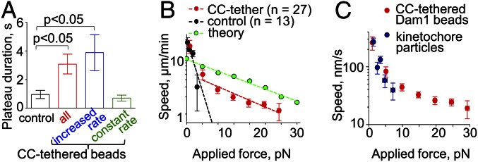
Reconstructed Dam1 couplers perform like purified yeast kinetochores. (A) The duration of Dam1 bead attachment under maximal force is longest in CC-tethered beads with increased speed during phase III. (B) A force–velocity curve generated from the data for all CC-tethered beads’ motions from phases III and IV (Fig. S2_C_). Dotted lines show exponential fitting plotted on a semilog scale; the fitting for CC-tethered beads is for motions recorded with the load >5 pN. The theoretical curve is from ref. 17. (C) Comparison of the force–velocity curve for CC-tethered beads vs. measurements for the kinetochore particles (data from ref. 24).
We have used these data to build a force–velocity curve for Dam1 coupling. With control beads, the rate of motion decreased fast with increasing load, like the behavior reported in ref. 21 for Dam1 conjugation directly to bead surface (Fig. 6_B_). Forces >5 pN resulted in the detachment of 100% of control beads. The force–velocity curve for CC-tethered and control beads was similar in its initial segment, consistent with our above finding that the mode of Dam1–cargo tethering is not important for motions under a small load. However, the CC-tethered beads could follow shortening MTs under much larger forces (Fig. 6_B_). The slope of the experimental force–velocity curve for a tethered Dam ring is similar to the slope predicted by the forced-walk model. However, the reconstructed coupler seems to perform less well than the theoretical ring; perhaps future experiments using a different protein tether or differently tagged Dam1 may produce even larger forces.
Discussion
The multiprotein Dam1 complex is a fascinating and well-studied kinetochore–MT coupling protein, but the mechanism by which it tracks dynamic MT ends and the way it carries a load have been controversial. Previous work in vitro has measured only a small <5 pN force in conjunction with Dam1 and MT disassembly (7, 8). Under load, Dam1-coated beads detached frequently from a shortening MT end, raising doubts that Dam1 alone would be a good enough coupler to produce processive chromosome motion or alternatively, that yeast kinetochores ever experience large MT-based forces in vivo (23). Here, we show that Dam1 rings suspended with long heterologous tethers in vitro can withstand loads of up to 30 pN. This finding is in tune with the past force measurements in live grasshopper spermatocytes, where the poleward force on chromosomes was measured (2). Furthermore, our results with the CC-tethered Dam1 beads are remarkably similar to the observations on isolated yeast kinetochores reported in ref. 24. Thus, the Dam1 complex alone, suspended on long protein tethers, is likely to correspond to the force-transducing coupling of a budding yeast kinetochore. Both isolated kinetochores and tethered Dam1 can move processively under significant load (Fig. 6_C_). In fact, the reconstituted Dam1 coupling sustains even larger forces, presumably because the kinetochore particles were purified with substoichiometric amounts of Dam1 (13, 24) and full rings formed only rarely.
At yeast kinetochores, Dam1 tethering may be provided by the 60-nm-long Ndc80 complex, which also binds MTs on its own and participates in kinetochore–MT interactions (25). Although Dam1 and Ndc80 do not interact in solution, Dam1 enhances the binding of Ndc80 to MTs and imparts to it the ability to track with depolymerizing MT ends (26–28). Interestingly, Ndc80-coated beads supplemented with soluble Dam1 can withstand, on average, only a 4.4-pN load, with the largest measured force of 9 pN (26). The much smaller force recorded with Ndc80-conjugated beads vs. the heterologous protein tether can be attributed, in part, to technical differences between these studies. Ndc80 beads were examined using a trap with a lower force limit (10–12 pN) in the presence of soluble tubulin, and therefore, under the load, shortening MTs frequently switched to growth. Future work will determine whether purified Ndc80 and Dam1 can provide a strong load-bearing coupler on their own, or whether this function is assisted by some additional kinetochore components.
In summary, our results with a heterologous protein tether suggest that the fibrillar shape of multiple protein complexes found at the kinetochore is crucial for the proper function of the kinetochore–MT interface. We suggest that the fibrillar network observed at the outer kinetochore of all eukaryotic cells examined (29, 30) plays a critical role in providing an environment suitable for stable and mechanically optimal attachments between chromosomes and spindle fibers through a ring, directly through the fibrils (31), or with the help of some other MT binding component, such as the Ska1 complex (32).
Materials and Methods
Cloning and Purification of GFP-Tagged Dam1 Complex and CC Tether.
The original Dam1 cloning plasmids were a gift from D. Drubin and G. Barnes (University of California, Berkeley, CA). The CC tether was constructed using a 700-aa fragment of rat α-myosin-6 heavy chain (a gift from Robert Thompson, University of Colorado, Boulder, CO). This fragment was mutated at five residues (D1238E, K1928A, R1930A, K1932A, and R1934A). A gene for GBP (19) was cloned into the XhoI site of the pET3a-myosin plasmid. Detailed information about cloning of these genes and protein purification is provided in SI Materials and Methods.
Mechanical Model of MT–Ring–Bead Interaction.
MT was modeled as a hollow tube ending with 13 flared and initially unstrained protofilaments (Fig. 3_A_ and Table S1). The MT minus end (shown at the top in Fig. 3_A_) was fixed. The geometry of the Dam1 ring was modeled based on its known structure, with 13 inward linkers moving freely on the MT surface (17). The ring’s initial position was at the junction between the MT cylinder and bent protofilaments. A bead was firmly attached to the ring; a linear force field was applied at the bead’s center, representing an isotropic trap. The elastic bending of the MT under torque was as described in ref. 18. The stiffness of the trap and the bending stiffness of the protofilaments as well as the rigidity of Dam1 inward linkers were varied (Table S1) and found to have only minor impact on the lever arm effect. Calculations of the displacements of all system parts and the corresponding forces were carried out with the ANSYS software package (ANSYS). The results shown in Fig. 3_C_ were obtained for the following values of model parameters: protofilament bending stiffness = 98.3 kcal/(mol rad2), Dam1 linker rigidity modulus = 106 pN/nm2, and trap stiffness = 0.03 pN/nm. Data in Fig. 3_D_ were generated based on geometrical considerations for the fixed ring–bead distance (100 nm), whereas the angle-α was varied as indicated.
Measurement of Dam1 Diffusion.
The surface of 22 × 22-mm glass coverslips (VWR) was silanized, coated with antitubulin antibodies (clone TU-20; Serotec), blocked with 1% Pluronic F-127 (Sigma) (33), and used to assemble a flow chamber (34). To allow the unimpeded formation of rings around MTs, we used microfabricated ribbed coverslips with podiums that were 5 μm wide and 100 nm high separated by 5-μm-wide gaps. These podiums were made by deposition of powdered silicon oxide using a mask. Ribbed coverslips were functionalized as described above. Taxol-stabilized MTs were prepared as described (35), but DMSO was substituted with 25% (vol/vol) glycerol. MTs were added in imaging buffer: 80 mM K-Pipes (pH 6.9), 1 mM EGTA, 4 mM MgCl2, 0.5 mg/mL casein, 4 mg/mL BSA, 2 mM DTT, 0.1 mg/mL glucose oxidase, 20 μg/mL catalase, 20 mM glucose, 10 μM taxol, and 1% 2-mercaptoethanol. After adding fluorescent Dam1, chambers were rinsed with the imaging buffer to remove the unbound protein. A Nikon Eclipse-Ti inverted microscope equipped with a CFI APO 100× Nikon-TIRF N.A. 1.49 objective and iXon3 camera (Andor Technology) was used for total internal reflection of fluorescence (TIRF) experiments using regular coverslips. Excitation was provided by a 488-nm diode laser (100 mW maximum; Coherent) set to 5–10 mW. With ribbed coverslips, we used epifluorescence with a Zeiss Axioplan upright microscope as described (15), and the coverslips were imaged with a defocused beam of a 488-nm 50-mW Argon ion laser. Images were acquired at 10−3–10 frames/s, depending on the size of Dam1 oligomers. Detailed procedures for quantification of these images are provided in SI Materials and Methods.
Preparation of Dam1-Conjugated Beads.
Previous published work with Dam1 beads did not use chemical linkers; Dam1 was conjugated to the surface of streptavidin-coated beads with the help of biotinylated antibodies to a tagged component of the Dam1 complex (7, 8, 21). Here, the CC-tethered Dam1 beads were obtained by covalently attaching the CC tether chimeras to the amine-coated surface of 1-μm glass beads through their C-terminal cysteines using a bifunctional cross-linker that carried a succinimidyl at one end and a maleimide ester at the other. Amine-coated glass beads, 1 μm in diameter (Bangs Laboratories), were washed in PBS; then, 10 mM Sulfosuccinimidyl-4-(_N_-maleimidomethyl) cyclohexane-1-carboxylate (Pierce) was added to the beads and incubated for 30 min with vortexing. The reaction was quenched with 20 mM glycine, and after three washes with PBS, the beads were incubated with 1–2 μM CC tether for 2 h on ice with mixing every 15–20 min to promote conjugation of the CC tether’s C-terminal cysteine to the derivatized glass. The GBP sequence also contains two cysteines, but they did not appear to conjugate efficiently to the beads as seen from the eight times lower intensity of the GFP-Dam1 coating of such beads (Fig. S1_D_). The cysteine conjugation reaction was quenched with 10 mM DTT, and the beads were washed three times with PBS with 2 mM DTT and 5 mg/mL casein. The beads were incubated with 5 μM GFP-Dam1 for 1 h on ice with occasional mixing, washed three times with PBS supplemented with 2 mM DTT and 5 mg/mL casein, and then, washed one more time with BRB-80 supplemented with 2 mM DTT, 4 mM MgCl2, 0.5 mg/mL casein, and 4 mg/mL BSA. These beads were diluted 1:1 with the same buffer containing 2% 2-mercaptoethanol right before introduction into the experimental chamber. Control beads were prepared in the same way, but the CC tether was replaced with a 1:1 mixture of 1–2 μM anti-GFP IgG (Rockland) and 10 mM Tris(2-carboxyethyl)phosphine (Pierce). The number of bead-bound Dam1-GFP complexes was ∼8,000 molecules per bead on average, which was determined by dividing average intensity of beads (acquired with epifluorescence) by the intensity of a single GFP molecule (SI Materials and Methods). For a bead 1 μm in diameter, this density is 2,667 molecules/μm2. Assuming that one MT end can interact with protein molecules localized to a 50 × 50-nm area, this density corresponds to 6.7 molecules per MT end (Fig. S1_E_).
Bead motility experiments were performed and analyzed as described (8, 15). Flow chambers containing segmented microtubules were prepared as described (34). All experiments were carried out at 32 °C. Details are in SI Materials and Methods.
Laser Trapping Experiments.
Laser trap setup and stationary trap experiments were described previously (8); trap stiffness was 0.05–0.15 pN/nm. The feedback loop in the force-clamp setup was implemented by custom-written software in LabView 9 (National Instruments). Force was applied along the estimated direction of the MT (input as MT angle) by moving the piezo stage (Physik Instrumente). The quadrant photodetector signal was sampled at 400 Hz, whereas the piezo-stage position was updated at 100 Hz with a feedback coefficient equal to 0.3–0.5, making a force clamp with an effective update rate of 30–50 Hz. After a bead was trapped and the force clamp was turned on, the MT was uncapped as described above, and the bead was allowed to move for >1 μm (average of 1.7 ± 0.2 μm). The force clamp was then turned off, and the developing force was measured by allowing the MT to pull the bead from the center of a static trap. At the end of each experiment, trap stiffness was calibrated with the same bead using the equipartition method (36). Details about analysis of quadrant photodetector data are provided in SI Materials and Methods.
Supplementary Material
Supporting Information
Acknowledgments
The authors thank N. Kalyagina (Bauman Moscow State Technical University) for help with mathematical modeling, R. Thompson (University of Colorado) for the gift of the mutant myosin plasmid, M. Porter (University of Minnesota) for the gift of axonemes, M. Morphew (University of Colorado) for help with EM, M. Molodtsov (Center for Theoretical Problems of Physicochemical Pharmacology) for help with LabView and MatLab software, and the other members of the laboratories of F.I.A. and E.L.G. for discussions. This study was supported in part by Russian Fund for Basic Research Grant 12-04-00111-a, a Dmitry Zimin Dynasty Foundation Postdoctoral Fellowship (to V.A.V.), Russian Academy of Sciences Presidium Grants (to F.I.A.; Mechanisms of the Molecular Systems Integration and Molecular and Cell Biology programs), National Institutes of Health Grants GM033787 (to J.R.M.) and GM098389 (to E.L.G.), and the McCabe Pilot Award (to E.L.G.). E.L.G. is a Kimmel Scholar.
Footnotes
The authors declare no conflict of interest.
References
- 1.Nicklas RB. Chromosome velocity during mitosis as a function of chromosome size and position. J Cell Biol. 1965;25(1965):119–135. doi: 10.1083/jcb.25.1.119. [DOI] [PMC free article] [PubMed] [Google Scholar]
- 2.Nicklas RB. Measurements of the force produced by the mitotic spindle in anaphase. J Cell Biol. 1983;97(2):542–548. doi: 10.1083/jcb.97.2.542. [DOI] [PMC free article] [PubMed] [Google Scholar]
- 3.Grishchuk EL, McIntosh JR. Microtubule depolymerization can drive poleward chromosome motion in fission yeast. EMBO J. 2006;25(20):4888–4896. doi: 10.1038/sj.emboj.7601353. [DOI] [PMC free article] [PubMed] [Google Scholar]
- 4.Tanaka K, Kitamura E, Kitamura Y, Tanaka TU. Molecular mechanisms of microtubule-dependent kinetochore transport toward spindle poles. J Cell Biol. 2007;178(2):269–281. doi: 10.1083/jcb.200702141. [DOI] [PMC free article] [PubMed] [Google Scholar]
- 5.Cheeseman IM, Desai A. Molecular architecture of the kinetochore-microtubule interface. Nat Rev Mol Cell Biol. 2008;9(1):33–46. doi: 10.1038/nrm2310. [DOI] [PubMed] [Google Scholar]
- 6.McIntosh JR, Volkov V, Ataullakhanov FI, Grishchuk EL. Tubulin depolymerization may be an ancient biological motor. J Cell Sci. 2010;123(Pt 20):3425–3434. doi: 10.1242/jcs.067611. [DOI] [PMC free article] [PubMed] [Google Scholar]
- 7.Asbury CL, Gestaut DR, Powers AF, Franck AD, Davis TN. The Dam1 kinetochore complex harnesses microtubule dynamics to produce force and movement. Proc Natl Acad Sci USA. 2006;103(26):9873–9878. doi: 10.1073/pnas.0602249103. [DOI] [PMC free article] [PubMed] [Google Scholar]
- 8.Grishchuk EL, et al. The Dam1 ring binds microtubules strongly enough to be a processive as well as energy-efficient coupler for chromosome motion. Proc Natl Acad Sci USA. 2008;105(40):15423–15428. doi: 10.1073/pnas.0807859105. [DOI] [PMC free article] [PubMed] [Google Scholar]
- 9.Laan L, et al. Cortical dynein controls microtubule dynamics to generate pulling forces that position microtubule asters. Cell. 2012;148(3):502–514. doi: 10.1016/j.cell.2012.01.007. [DOI] [PMC free article] [PubMed] [Google Scholar]
- 10.Oguchi Y, Uchimura S, Ohki T, Mikhailenko SV, Ishiwata S. The bidirectional depolymerizer MCAK generates force by disassembling both microtubule ends. Nat Cell Biol. 2011;13(2011):1–8. doi: 10.1038/ncb2256. [DOI] [PubMed] [Google Scholar]
- 11.Powers AF, et al. The Ndc80 kinetochore complex forms load-bearing attachments to dynamic microtubule tips via biased diffusion. Cell. 2009;136(5):865–875. doi: 10.1016/j.cell.2008.12.045. [DOI] [PMC free article] [PubMed] [Google Scholar]
- 12.Cheeseman IM, Enquist-Newman M, Müller-Reichert T, Drubin DG, Barnes G. Mitotic spindle integrity and kinetochore function linked by the Duo1p/Dam1p complex. J Cell Biol. 2001;152(1):197–212. doi: 10.1083/jcb.152.1.197. [DOI] [PMC free article] [PubMed] [Google Scholar]
- 13.Gonen S, et al. The structure of purified kinetochores reveals multiple microtubule-attachment sites. Nat Struct Mol Biol. 2012;19(9):925–929. doi: 10.1038/nsmb.2358. [DOI] [PMC free article] [PubMed] [Google Scholar]
- 14.Westermann S, et al. The Dam1 kinetochore ring complex moves processively on depolymerizing microtubule ends. Nature. 2006;440(7083):565–569. doi: 10.1038/nature04409. [DOI] [PubMed] [Google Scholar]
- 15.Grishchuk EL, et al. Different assemblies of the DAM1 complex follow shortening microtubules by distinct mechanisms. Proc Natl Acad Sci USA. 2008;105(19):6918–6923. doi: 10.1073/pnas.0801811105. [DOI] [PMC free article] [PubMed] [Google Scholar]
- 16.Ramey VH, et al. The Dam1 ring binds to the E-hook of tubulin and diffuses along the microtubule. Mol Biol Cell. 2011;22(4):457–466. doi: 10.1091/mbc.E10-10-0841. [DOI] [PMC free article] [PubMed] [Google Scholar]
- 17.Efremov A, Grishchuk EL, McIntosh JR, Ataullakhanov FI. In search of an optimal ring to couple microtubule depolymerization to processive chromosome motions. Proc Natl Acad Sci USA. 2007;104(48):19017–19022. doi: 10.1073/pnas.0709524104. [DOI] [PMC free article] [PubMed] [Google Scholar]
- 18.Grishchuk EL, Molodtsov MI, Ataullakhanov FI, McIntosh JR. Force production by disassembling microtubules. Nature. 2005;438(7066):384–388. doi: 10.1038/nature04132. [DOI] [PubMed] [Google Scholar]
- 19.Rothbauer U, et al. Targeting and tracing antigens in live cells with fluorescent nanobodies. Nat Methods. 2006;3(11):887–889. doi: 10.1038/nmeth953. [DOI] [PubMed] [Google Scholar]
- 20.Tanaka TU, Stark MJR, Tanaka K. Kinetochore capture and bi-orientation on the mitotic spindle. Nat Rev Mol Cell Biol. 2005;6(12):929–942. doi: 10.1038/nrm1764. [DOI] [PubMed] [Google Scholar]
- 21.Franck AD, et al. Tension applied through the Dam1 complex promotes microtubule elongation providing a direct mechanism for length control in mitosis. Nat Cell Biol. 2007;9(7):832–837. doi: 10.1038/ncb1609. [DOI] [PMC free article] [PubMed] [Google Scholar]
- 22.Gestaut DR, et al. Phosphoregulation and depolymerization-driven movement of the Dam1 complex do not require ring formation. Nat Cell Biol. 2008;10(4):407–414. doi: 10.1038/ncb1702. [DOI] [PMC free article] [PubMed] [Google Scholar]
- 23.Asbury CL, Tien JF, Davis TN. Kinetochores’ gripping feat: Conformational wave or biased diffusion? Trends Cell Biol. 2011;21(1):38–46. doi: 10.1016/j.tcb.2010.09.003. [DOI] [PMC free article] [PubMed] [Google Scholar]
- 24.Akiyoshi B, et al. Tension directly stabilizes reconstituted kinetochore-microtubule attachments. Nature. 2010;468(7323):576–579. doi: 10.1038/nature09594. [DOI] [PMC free article] [PubMed] [Google Scholar]
- 25.Cheeseman IM, Chappie JS, Wilson-Kubalek EM, Desai A. The conserved KMN network constitutes the core microtubule-binding site of the kinetochore. Cell. 2006;127(5):983–997. doi: 10.1016/j.cell.2006.09.039. [DOI] [PubMed] [Google Scholar]
- 26.Tien JF, et al. Cooperation of the Dam1 and Ndc80 kinetochore complexes enhances microtubule coupling and is regulated by aurora B. J Cell Biol. 2010;189(4):713–723. doi: 10.1083/jcb.200910142. [DOI] [PMC free article] [PubMed] [Google Scholar]
- 27.Lampert F, Hornung P, Westermann S. The Dam1 complex confers microtubule plus end-tracking activity to the Ndc80 kinetochore complex. J Cell Biol. 2010;189(4):641–649. doi: 10.1083/jcb.200912021. [DOI] [PMC free article] [PubMed] [Google Scholar]
- 28.Lampert F, Mieck C, Alushin GM, Nogales E, Westermann S. Molecular requirements for the formation of a kinetochore-microtubule interface by Dam1 and Ndc80 complexes. J Cell Biol. 2013;200(1):21–30. doi: 10.1083/jcb.201210091. [DOI] [PMC free article] [PubMed] [Google Scholar]
- 29.Dong Y, Vanden Beldt KJ, Meng X, Khodjakov A, McEwen BF. The outer plate in vertebrate kinetochores is a flexible network with multiple microtubule interactions. Nat Cell Biol. 2007;9(5):516–522. doi: 10.1038/ncb1576. [DOI] [PMC free article] [PubMed] [Google Scholar]
- 30.McIntosh JR, et al. Conserved and divergent features of kinetochores and spindle microtubule ends from five species. J Cell Biol. 2013;200(4):459–474. doi: 10.1083/jcb.201209154. [DOI] [PMC free article] [PubMed] [Google Scholar]
- 31.McIntosh JR, et al. Fibrils connect microtubule tips with kinetochores: A mechanism to couple tubulin dynamics to chromosome motion. Cell. 2008;135(2):322–333. doi: 10.1016/j.cell.2008.08.038. [DOI] [PMC free article] [PubMed] [Google Scholar]
- 32.Schmidt JC, et al. The kinetochore-bound Ska1 complex tracks depolymerizing microtubules and binds to curved protofilaments. Dev Cell. 2012;23(5):968–980. doi: 10.1016/j.devcel.2012.09.012. [DOI] [PMC free article] [PubMed] [Google Scholar]
- 33.Varga V, et al. Yeast kinesin-8 depolymerizes microtubules in a length-dependent manner. Nat Cell Biol. 2006;8(9):957–962. doi: 10.1038/ncb1462. [DOI] [PubMed] [Google Scholar]
- 34.Grishchuk EL, Ataullakhanov FI. In: Methods in Cell Biology. Vol 95. Wilson L, Correia JJ, editors. Amsterdam: Elsevier; 2010. pp. 657–676. [DOI] [PMC free article] [PubMed] [Google Scholar]
- 35.Howard J, Hyman A. In: Methods in Cell Biology. Vol 39. Scholey JM, editor. Amsterdam: Elsevier; 1993. pp. 105–113. [Google Scholar]
- 36.Svoboda K, Block SM. Biological applications of optical forces. Annu Rev Biophys Biomol Struct. 1994;23(1994):247–285. doi: 10.1146/annurev.bb.23.060194.001335. [DOI] [PubMed] [Google Scholar]
Associated Data
This section collects any data citations, data availability statements, or supplementary materials included in this article.
Supplementary Materials
Supporting Information