Deploy Export-Function Component Configured for C Service Interface Code Generation - MATLAB & Simulink (original) (raw)
This example shows how to develop an export-function model as a component that includes service interface support for interacting with target platform software. In this example you:
- Assess project requirements.
- Define the service code interface configuration in the coder dictionary.
- Design the component model.
- Configure the component model interfaces for code generation.
- Assess component model readiness for code generation.
- Generate and inspect the generated component code.
- Test the generated service interface code by using a software-in-the-loop (SIL) or processor-in-the-loop (PIL) simulation.
- Get meta-information about the generated code interface for integration with target platform software.
- Integrate generated component code with target environment code.
Assess Project Requirements
This example assumes these component and target platform requirements.
Component Description and Interface Requirements
The component model must:
- Favor memory optimization over data freshness when communicating data.
- Include an initialize function that reads a value from nonvolatile memory and uses that value to initialize a state variable.
- Include an integrator function that applies a forward integration method, applies a gain value of 1.25 to the state variable, and sends its output to an accumulator function. The integrator function gets called aperiodically.
- Include an accumulator function that receives the value of the state variable from the integrator function, increments the value by one, and applies a gain value, which is tunable during execution. The accumulator function gets called periodically, every 1 second and maintains the most recent value of the state variable.
- Include a terminate function that writes the output of the algorithm function to nonvolatile memory after the function stops executing.
- Make state variables accessible for monitoring during execution.
Target Platform Interface Requirements
- To initiate component initialization, the target platform function scheduler expects to call entry-point function
CD_initializewith no arguments. - To initiate execution of the aperiodic integrator function, the target platform function scheduler expects to call entry-point function
CD_integratorwith no arguments. - To initiate execution of the periodic algorithm function, the target platform function scheduler expects to call entry-point function
CD_accumulatorwith no arguments. - To complete component termination, the target platform function scheduler expects to call entry-point function
CD_terminatewith no arguments. - The component reads from and writes to target platform nonvolatile memory.
- The platform receiver service function is named
get_CD_integrator_InBus_uand uses outside-execution data communication. For more information, see Data Communication Methods. - The platform sender service function is named
getref_CD_accumulator_OutBus_yand uses outside-execution data communication. - The platform data transfer service sender function is named
set_CD_integrator_DataTransfer, the receiver function is namedget_CD_accumulator_DataTransfer, and the service uses outside-execution data communication. - The platform timer service uses outside-execution. The get function clock tick service function is named
get_CD_tick_callable-function,wherecallable-functionisCD_integrator. The function returns the tick value as a value of typeuint32. - The variable for the tunable gain value applied by the accumulator function is named
CD_tunable.k. - Variables representing the discrete time integrator and delay state values are named
CD_measured.dtiandCD_measured.delay.
Define Service Code Interface Configuration
You address the target platform requirements by defining a service code interface configuration in a shared Embedded Coder Dictionary. For this example, the requirements are defined in the dictionary file ComponentDeploymentCoderDictionary.sldd, which is configured for the example model.
Open example component model ComponentDeploymentFcn.
open_system('ComponentDeploymentFcn');

Open the Embedded Coder Dictionary (ComponentDeploymentCoderdictionary.sldd), which is configured for the model.
- Open the Embedded Coder app.
- In the toolstrip, under Code interface, select
Embedded Coder Dictionary (Shared). The Embedded Coder Dictionary configured for the example model opens. You can create a coder dictionary in the Model Explorer (click File > New > Embedded Coder Dictionary) or in the model Configuration Parameters dialog box (click Set up to the right of the Shared coder dictionary parameter). - Under Service Interface, select Receiver. The Embedded Coder Dictionary shows content in three panes. Use the left pane to navigate through the dictionary configurations. The center pane lists the interfaces that are defined in a code interface configuration for the item you select in the navigation pane. From the center pane you can create and delete interfaces and specify a default interface. The right pane shows the property settings for the interface selected in the center pane. The Pseudocode Preview updates as you change property settings.

In the dictionary, browse through the interface settings. Check that the settings align with the requirements noted in Target Platform Requirements.
Based on requirements listed in Assess Project Requirements, the dictionary defines these relevant interfaces:
- Initialize and terminate callable entry-point function interface
InitTermInterface, which specifies naming ruleCD_$N, where$Nisinitializeorterminate, depending on the type of function generated. - Periodic and aperiodic callable entry-point function interface
PeriodicAperiodicInterface, which specifies naming ruleCD_$N, where$Nis the name of the function-call inport block. Later, you override the default naming in the code mappings. - Receiver service interface
ReceiverOutsideExespecifies outside-execution data communication. The interface specifies naming ruleget_$X_$N, where$Xis the name of the callable function and$Nis the name of the receiver port for the receive operation. - Sender service interfaces Sender
OutsideExespecifies outside-execution data communication. The interface specifies naming rulesset_$X_$Nandgetref_$X_$Nfor the by value and by reference functions, where$Xis the name of the callable function and$Nis the name of the sender port for the send operation. - Data transfer service interfaces
DataTransferOutsideExeandDataTransferDuringExe.DataTransferOutsideExe, the default, specifies outside-execution data communication.DataTransferDuringExespecifies during-execution data communication. Both interfaces specify naming rulesset_$X$Nandget_$X$N, where$Xis the name of the callable function and$Nis the name of the signal that represents the data transfer. - Timer service interfaces
TimerServiceandget_CD_tick.TimerService, the default, specifies outside-execution data communication and naming rule$G_tick_$X, where$Gtoken is the service nameTimerServiceand$Xis the name of the function that calls the service. Interfaceget_CD_tickspecifies outside-execution data communication and a naming rule that aligns with the project requirements,$G$X, where$Gis the service interface name and$Xis the name of the callable function. - Parameter tuning service interface
ParameterTuningServiceapplies storage classTunableStructto data elements. To align with the platform requirements for naming tunable parameters, property Type Name was set toCD_tunable_T$Mand property Instance Name was set toCD_tunable. - Measurement service interface,
MeasurementService, applies storage classMeasurementStruct. To align with the platform requirements for naming state data, property Type Name was set toCD_measured_T$Mand property Instance Name was set toCD_measured.
The during-execution receiver, sender, and data transfer service interfaces are defined so that you can explore differences in the generated code for the different data communication.
Later, in Configure Component Model Interface for Code Generation, you map elements of the example model to interfaces defined by the service interface configuration in the dictionary.
For more information about defining code interface configurations, see Code Interface Definitions and Embedded Coder Dictionary.
Design Component Model
The design of example component model ComponentDeploymentFcn reflects the requirements listed in Assess Project Requirements.
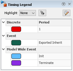
The timing legend for the model identifies four functions: two model-wide event-driven functions Init and Term, a discrete periodic function, and an exported event-driven (aperiodic) function. To open the timing legend, on the Debug tab, click Information Overlays > Timing Legend.
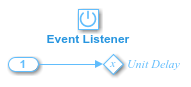
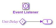
- The Initialize Function block represents a function that initializes a state variable
xwith a value read from nonvolatile memory before the algorithm executes. See cgsl_0404: Model startup and shutdown events by using Initialize Function and Terminate Function blocks for component deployment and cgsl_0411: Access nonvolatile memory.
- The In Bus Element block
InBus.NVM, which feeds the initialize function, represents a call to the platform service that reads values from nonvolatile memory. See cgsl_0402: Signal interfaces for component deployment and cgsl_0405: Data receive for component deployment. - Function-call subsystem
Integratorrepresents an integrator function. The function applies a forward integration method and a gain value of 1.25 to the value of state variablexeach time the function executes. See cgsl_0401: Modeling styles for component deployment.
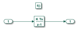
- The inport for Integrator,
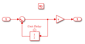
InBus.u, represents a call to the platform receiver service for reading the input value from the target environment. See cgsl_0402: Signal interfaces for component deployment and cgsl_0405: Data receive for component deployment. - Function-call subsystem Accumulator represents a function that increments the value of state variable
xby 1 and applies a tunable gain valuek. The function executes every second. See cgsl_0401: Modeling styles for component deployment.
- The signal line that connects the output port of function-call subsystem
Integratorto the input port of function-call subsystemAccumulatorrepresents a data transfer.Integratorcalls the data transfer service to send data toAccumulator.Accumulatorcalls the data transfer service to receive the data fromIntegrator. See cgsl_0409: Data transfer for component deployment. - The outport of
Accumulatorrepresents a call to the platform sender service for writing the output value of the Gain block. See cgsl_0402: Signal interfaces for component deployment and cgsl_0406: Data send for component deployment. - The Terminate Function block represents the function that writes the output of
Accumulatorto nonvolatile memory after the component stops executing. See cgsl_0404: Model startup and shutdown events by using Initialize Function and Terminate Function blocks for component deployment and cgsl_0411: Access nonvolatile memory.
- The outport of the terminate function represents a call to the platform service that writes values to nonvolatile memory. See cgsl_0402: Signal interfaces for component deployment and cgsl_0406: Data send for component deployment.
For more information about modeling guidelines that can help you develop and deploy component models that use a service code interface, see Modeling Guidelines for Generated Code.
Configure Component Model Interface for Code Generation
For the code generator to produce interface code that aligns with the target environment requirements, there needs to be a mapping between the interface elements in the model and code interfaces. A model can be associated with one of three types of code interfaces: data interface, service interface, or C++ interface. The code generator determines the type of code interface to apply automatically based on this information:
- Modeling styles and patterns used in the model
- Embedded Coder app Output selection
- Type and contents of the Embedded Coder Dictionary associated with the model
For this example, the code generator applies a service interface because the model is configured to use shared Embedded Coder Dictionary ComponentDeploymentCoderDictionary.sldd, which defines a service interface configuration. The code generator uses the configured dictionary to establish default mappings that you can view and change by using the Code Mappings Editor or code mappings programming interface.
To open the Code Mappings editor and explore the interface settings, in the toolstrip, under Code Interface, select Component Interface.

For elements for which the default interface aligns with the requirements, you do not need to make changes. Depending on your model, your code generation goals, and available interfaces, you might need to make some adjustments.
For this example, to meet the code interface requirements listed in Assess Project Requirements, these adjustments were made:
- On the Functions tab, the default function customization template for the aperiodic integrator and periodic accumulator functions produces function names
CD_AperiodicandCD_Periodic. To align with target platform requirements for these functions, the code mappings override the default functions names, by specifying the function namesCD_integratorandCD_accumulator. - An alternate timer service interface was associated with the integrator function. The coder dictionary defines two timer service interfaces: the default interface and an alternate interface get_CD_tick, which aligns with the target platform timer service requirements for function names. To see the timer service setting, on the Functions tab, select the row for
Exported Function:Aperiodicand click the pencil icon. In the dialog box that appears, see that the Timer Service property is set toget_CD_tick. Alternatively, you can set the property in the Property Inspector. - On the Parameters tab, a code identifier was specified for the Gain block gain parameter
k. To see the identifier setting, under Model Parameters, select the row for the parameter and click the pencil icon. In the dialog box that appears, see the value specified for the Identifier property, k. The identifier informs the code generator how to represent the variable in the generated code. Alternatively, you can set the property in the Property Inspector. - On the Signals/States tab, code identifiers were specified for the states associated with the Discrete-Time Integrator and Unit Delay blocks. To see the identifier settings (
dtianddelay), select the row for the state of interest and click the pencil icon. In the dialog box that appears, see the value specified for the Identifier property. The identifiers inform the code generator how represent corresponding variables in the generated code. Alternatively, you can set the property in the Property Inspector.
In the Code Mappings editor, you can change the interfaces for the sender, receiver, data transfer, and timer services. To change the sender, receiver, and data transfer service, click the corresponding tab and, in the service column, select an alternative service. To change the timer service, click the Functions tab, select the row for the integrator function, click the pencil icon, and in the dialog that appears, select an alternative interface. The default interfaces use the outside-execution data communication method. The alternative interfaces use during-execution and direct-access data communication. Consider changing the interfaces to view differences in the generated code. If you choose to change the interfaces, for each service called along the data path of a signal, set the interfaces such that they apply the same data communication method.
For guidance on setting up a model to use a service interface configuration, see cgsl_0414: Configure service interface for component model. For more information about model code mappings for service interfaces, see C Service Interfaces and Code Mappings Editor — C.
Assess Component Model Readiness for Code Generation
Run the Simulink Model Advisor to confirm that the component model passes component modeling guideline checks.
- In the Embedded Coder app, select C/C++ Code Advisor.
- In the System Selector dialog box, select
ComponentDeploymentFcn. Click Ok. - In the Code Generation Advisor dialog box, in the left pane, select Model Advisor.
- In the Model Advisor dialog box, in the left pane, expand
By ProductandEmbedded Coder. - Select the checks Check modeling style for component deployment, Check signal interfaces, and Check configuration for component deployment.
- Run the selected checks.
If the checks do not pass, use the information provided to correct the conditions reported.
For more information, see Modeling Guidelines for Generated Code and Model Readiness for Code Generation.
Generate and Inspect Generated Component Code
In the toolstrip, click Generate Code.
From the component model, the code generator creates the folder ComponentDeploymentFcn_ert_rtw in the current working folder and places source code files in that folder. The generated code is in two primary files: header file ComponentDeploymentFcn.h and source code file ComponentDeploymentFcn.c. Model data and entry-point functions are accessible to a caller by including the header file.
The code generator also produces an interface header file in subfolder services, which by default the code generator names services.h. This file includes declarations for platform service interface functions called by the component code.
To inspect the generated code, use the generated Code Interface Report or, in the Embedded Coder app, use the Code view. The report is helpful for verifying that the generated interface code aligns with the target platform requirements.
For each callable entry-point function, the Code Interface Report provides:
- Function prototype
- Description
- Header file name
- Information about platform services called, such as prototypes and data communication method used
For each platform service called, the report provides:
- Function prototypes
- Data communication method used
- Callable functions that call the service
For more information, see Analyze Generated Service Code Interface Report.
Header File
Header file ComponentDeploymentFcn.h includes interface header file services.h, defines an instance of the real-time model data structure, and declares:
- Structure for representing DWork vectors
- Structure for representing measurable state data
- Structure for representing tunable parameters
- Structure for representing timing data
- Callable entry-point functions
#include "ComponentDeploymentFcn_types.h" #include "services.h" #define ComponentDeploymentFcn_M (rtM)
typedef struct { real_T DataTransfer_WriteBuf[10]; real_T DiscreteTimeIntegrator_PREV_U[10]; uint32_T Integrator_PREV_T; uint8_T DiscreteTimeIntegrator_SYSTEM_E; boolean_T Integrator_RESET_ELAPS_T; } D_Work;
typedef struct {
real_T delay[10];
real_T dti[10];
} CD_measured_T;
typedef struct { real_T gain; } CD_tunable_T;
struct tag_RTM { struct { uint32_T clockTick2; uint8_T rtmH2LBufBeingRead2; uint8_T rtmH2LLastBufWr2; uint32_T rtmH2LDbBufClockTick2[2]; } Timing; };
extern D_Work rtDWork; extern void CD_initialize(void); extern void CD_terminate(void); extern void CD_accumulator(void); extern void CD_integrator(void); extern CD_measured_T CD_measured; extern CD_tunable_T CD_tunable; extern RT_MODEL *const rtM;
Source Code File
The generated source code file ComponentDeploymentFcn.c shows the code for the four functions represented in the component model.
- Accumulator function calls the data transfer service function
get_CD_accumulator_DataTransfer()to read an input value transferred from functionCD_integrator. For each element of the bus signal, the function applies a delay and gain value and writes the output by calling sender service functiongetref_CD_accumulator_OutBus_y. - Integrator function sets the elapsed time value to 0, if initialized, or to the current elapsed time. The integrator function calculates the current elapsed time by subtracting the cached elapsed time value (
rtDWork.Integrator_PREV_T)from the current tick value that the function gets by calling the timer service function get_tick_outside_CD_integrator. The code generator assumes that the resolution of the clock is the fundamental step size of the model. The function uses the calculated elapsed time to calculate the integration and calls the receiver service functionget_CD_integrator_InBus_uto receive the next input value. - Initialize function calls the data transfer service function**
set_ModelInitialize_DataTransfer**and receiver service functionget_CD_initialize_InBus_NVMto initialize state data that is read from nonvolatile memory. - Terminate function calls the sender service function
getref_CD_terminate_OutBus_NVMto write the output of the accumulator function to memory.
#include "rtwtypes.h" #include <string.h> #include "ComponentDeploymentFcn.h" #include "services.h"
CD_measured_T CD_measured; CD_tunable_T CD_tunable = {
3.0 };
D_Work rtDWork; static RT_MODEL rtM_; RT_MODEL *const rtM = &rtM_; void CD_accumulator(void) { const real_T *tmpIrvIRead; int32_T i; tmpIrvIRead = get_CD_accumulator_DataTransfer(); for (i = 0; i < 10; i++) { CD_measured.delay[i] += tmpIrvIRead[i]; (getref_CD_accumulator_OutBus_y())[i] = CD_tunable.gain * CD_measured.delay[i]; } }
void CD_integrator(void) { real_T tmp; real_T *tmp_0; int32_T i; uint32_T Integrator_ELAPS_T; tmp_0 = set_CD_integrator_DataTransfer(); if (rtDWork.Integrator_RESET_ELAPS_T) { Integrator_ELAPS_T = 0U; } else { Integrator_ELAPS_T = (uint32_T)(get_tick_outside_CD_integrator() - rtDWork.Integrator_PREV_T); }
rtDWork.Integrator_PREV_T = get_tick_outside_CD_integrator(); rtDWork.Integrator_RESET_ELAPS_T = false; tmp = 1.25 * (real_T)Integrator_ELAPS_T; for (i = 0; i < 10; i++) { if ((int32_T)rtDWork.DiscreteTimeIntegrator_SYSTEM_E == 0) { CD_measured.dti[i] += tmp * rtDWork.DiscreteTimeIntegrator_PREV_U[i]; }
rtDWork.DiscreteTimeIntegrator_PREV_U[i] = (get_CD_integrator_InBus_u())[i];}
rtDWork.DiscreteTimeIntegrator_SYSTEM_E = 0U; memcpy(&tmp_0[0], &CD_measured.dti[0], (uint32_T)(10U * sizeof(real_T))); }
void CD_initialize(void) { { real_T *tmp; int32_T i; tmp = set_ModelInitialize_DataTransfer(); for (i = 0; i < 10; i++) { tmp[i] = 5.0; }
memcpy(&CD_measured.delay[0], &(get_CD_initialize_InBus_NVM())[0], (uint32_T)
        (10U * sizeof(real_T)));
rtDWork.Integrator_RESET_ELAPS_T = true;
rtDwork.DiscreteTimeIntegrator_SYSTEM_E = 1U;
} }
void CD_terminate(void) { memcpy(&(getref_CD_terminate_OutBus_NVM())[0], &CD_measured.delay[0], (uint32_T) (10U * sizeof(real_T))); }
Services Header File
The services header file services.h declares prototypes for calling services that run as platform software in a target environment.
/* timer services */ extern uint32_T get_tick_outside_CD_integrator(void);
/* data transfer services */ const real_T * get_CD_accumulator_DataTransfer(void); real_T * set_CD_integrator_DataTransfer(void); real_T * set_ModelInitialize_DataTransfer(void);
/* receiver services */ extern const real_T * get_CD_integrator_InBus_u(void); extern const real_T * get_CD_initialize_InBus_NVM(void);
/* sender services */ extern real_T * getref_CD_accumulator_OutBus_y(void); extern real_T * getref_CD_terminate_OutBus_NVM(void);
Test Generated Service Interface Code by Using SIL and PIL Simulations
Consider using a software-in-the-loop (SIL) and processor-in-the-loop (PIL) simulations to verify the generated code. A SIL simulation compiles and runs the generated code on your development computer. A PIL simulation compiles and runs the generated code on a target computer. During a SIL and PIL simulations, you can collect code coverage and execution-time metrics for the generated code.
To test numeric equivalence between the model and generated code:
- Run a normal mode simulation and capture the results.
- Run a SIL or PIL simulation and capture the results.
- Compare the results from steps 1 and 2.
To run SIL and PIL simulations on the example model, you can use the example test harness model ComponentDeploymentFcnTestHarness.slx and data file ComponentDeploymentBus.mat.
For more information, see Software-in-the-Loop Simulation and Processor-in-the-Loop Simulation.
Get Meta-Information About Generated Code Interface for Integration
By default, the code generator creates a code descriptor file (codedescriptor.dmr) in the build folder. That file contains meta-information about the generated code, including:
- Data interfaces (inports, outports, parameters, datastores, and internal data)
- Function interfaces (initialize, output, update, and terminate)
- Execution information for the data and function interfaces, such as timing requirements
- Model hierarchy information and information for referenced models
You can use the code descriptor programming interface to get access to the contents of the code descriptor file and use the results to confirm that generated interfaces meet integration requirements. You can also use the programming interface to provide input to tools that generate interfaces for target platform services.
For more information, see Get Code Description of Generated Code and coder.codedescriptor.CodeDescriptor class.
Integrate Generated Component Code with Target Environment Code
To integrate the generated component code with a main function and other target environment code, you must:
- Match the data and function interfaces of the generated code with other interfaces of existing system code.
- Connect input data.
- Connect output data.
- Access other data, such as block state values, local parameters, and time.
The model used in this example is designed and configured such that the generated code aligns with the code interfaces of the target environment.
- The target environment software calls the generated entry-point functions, which provide input signal data and scheduling information.
- The generated algorithm calculates output data that the calling environment uses.
- The set of input and output data and the data access mechanisms constitute the interfaces of the entry-point functions.
In a model, root-level inports and outports represent the primary inputs and outputs of the component algorithm. By default, the code generator aggregates this input and output data into standard structures.
You can generate code for a component model and compile a component model library by clearing model configuration parameter Generate code only and initiating a model build. If code for the component model is already generated, you can build a component model library by using the codebuild command with the path codeGenerationFolder/ modelBuildFolder/services/lib. You can link the generated component model library with a main function and other target environment code to create an executable program.
For the component model library, you can also create a:
- CMake configuration (
CMakeLists.txt) file by using thecodebuildfunction - ZIP file by setting model configuration parameter Package code and artifacts and using the
packNGofunction
For more information, see Manage Build Process Folders, Approaches for Building Code Generated from Simulink Models, Configure CMake Build Process, Compile Code in Another Development Environment, and Deploy Component Algorithm as Component Model Library by Using CMake.
For examples, see Configure Generated Code According to Interface Control Document Specifications and Integrate External Application Code with Code Generated from PID Controller.
For more information, see Deployment, Integration, and Supported Hardware.
Related Examples
- Generate Sender and Receiver C Interface Code for Component Deployment
- Generate C Data Transfer Service Interface Code for Component Deployment
- Generate C Timer Service Interface Code for Component Deployment
- Generate C Parameter Tuning Service Interface Code for Component Deployment
- Generate C Measurement Service Interface Code for Component Deployment