Critical Path Estimation Without Running Synthesis - MATLAB & Simulink (original) (raw)
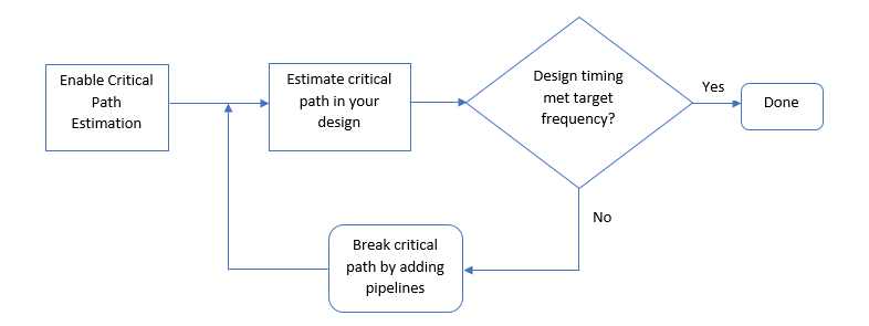
The critical path is the combinational path between an input and output that has the maximum timing delay. To find the critical path in your design, use HDL Coder™. To make the critical path timing meet the target frequency that you want your design to achieve, break the critical path by adding delays. The additional delays increase the latency and register usage on the target FPGA.
To quickly identify the most likely critical path in your design, use critical path estimation. You then do not have to run synthesis or generate HDL code. Critical path estimation speeds up this iterative process of finding the critical path. It optimizes the critical path until your design timing meets the target frequency that you want.
Critical path estimation speeds up the design iteration process. Critical path estimation is an alternative to annotating the critical path by performingFPGA Synthesis and Analysis with the HDL Workflow Advisor.
Critical Path Estimation Process
HDL Coder finds the estimated critical path by performing static timing analysis with timing data from target-specific timing databases. Generate timing databases for a specified target device family, target device speed grade, and target tool by using the genhdltdb function. By default, HDL Coder has timing databases for these target devices:
- Altera® Cyclone V
- Intel® Stratix V
- Xilinx® Artix®-7, speed grade -1
- Xilinx Kintex®-7, speed grade -1
- Xilinx Kintex UltraScale™, speed grade -1
- Xilinx Virtex®-4, speed grade -10
- Xilinx Virtex-7, speed grade -1
- Xilinx Zynq®, speed grade -1
- Xilinx Zynq UltraScale+™, speed grade -1
To create timing databases, HDL Coder characterizes basic design components, such as Simulink® blocks, block architectures, and subcomponents of those blocks, for specific target devices.
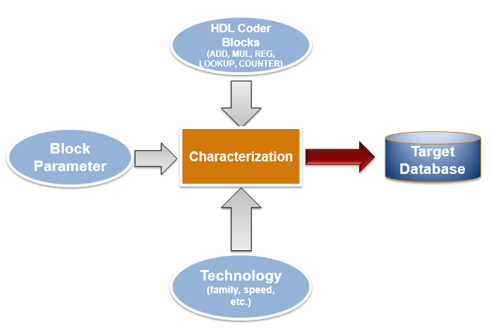
The code generator analyzes your model design to decompose it into the blocks and subcomponents in the timing databases. If your design consists of blocks or subcomponents in the timing databases, the code generator can estimate the timing critical path more accurately. If your design uses components that are not in the timing databases, a separate highlighting script is generated to show the uncharacterized blocks. If the timing data is incomplete for parts of your design, it is possible that the estimated critical path does not match your actual critical path.
If your target hardware is one of the target devices supported for critical path estimation, the timing numbers and estimated critical path are more accurate. If your target hardware is not a supported device, or is not in the same device family, you can estimate the critical path, but it is possible that the timing numbers are not accurate.
Use Critical Path Estimation
You can estimate the critical path for your design in the Configuration Parameters dialog box or at the command line. To estimate the critical path in the Configuration Parameters dialog box:
- Enable generation of critical path estimation report.
- In the Apps tab, select HDL Coder.
- In the HDL Code tab, select > , and then select Generate high-level timing critical path report.
- Disable HDL code generation for your model. In the > > tab, clear the Generate HDL Code check box.
To estimate the critical path in your design, you do not have to run the complete code generation process. When you disable HDL code generation, you run the process until HDL Coder creates the generated model and displays the critical path estimation script. You avoid running a larger portion of the code generation process, which saves time in estimating the critical path, especially for large models. - If your design contains floating-point data types, enable the
Native Floating Pointmode. In the Configuration Parameters dialog box, on the > pane, select Use Floating Point. - Set the path of the generated timing databases for your target device. In the Configuration Parameters dialog box, on the > pane, select the Generate high-level timing critical path report parameter, and then set the path of your generated timing databases by clickingBrowse and selecting the target folder.
By default, the target folder shows some of the saved timing database folders based on your target configuration. If the Custom Timing Database Directory box is empty or the target configuration has no timing databases, by default, HDL Coder uses timing databases for the Xilinx Virtex -7, speed grade -1 device to generate the critical path estimation report.
You can also generate timing databases for a specified target device family, target device speed grade, and target tool by using thegenhdltdb function. - Generate a critical path estimation report. In the HDL Code Generation pane, click Apply, and then click Generate.
HDL Coder generates a critical path estimation report and displays messages in the MATLAB® Command Window that include a link to a highlighting script and a script that clears the highlighting.
To generate the report at the command line, use this code. Specify themodelname and dutname variables based on the design for which you want to estimate the critical path. Set the path of the generated timing databases for your target device by using the hdlset_param function. When you enable the generation of the critical path estimation report and do not set the timing database path for a target device, HDL Coder searches for the default timing databases for the specified target device family and target device speed grade. If timing databases for the specified target device are not available, by default, HDL Coder uses timing databases for the Xilinx Virtex-7, speed grade -1 device to generate the critical path estimation report. This example uses the sfir_single model.
% Specify model and subsystem names modelname = 'sfir_single'; dutname = 'sfir_single/symmetric_fir'; open_system(modelname)
% Disable HDL code generation for faster generation % of critical path estimation report hdlset_param(modelname,'CriticalPathEstimation','on'); hdlset_param(modelname,'GenerateHDLCode','off');
% If design contains single data types, % enable native floating-point support fpconfig = hdlcoder.createFloatingPointTargetConfig('NativeFloatingPoint'); hdlset_param(modelname,'FloatingPointTargetConfig',fpconfig);
% Set path of generated timing databases for target device hdlset_param(modelname,'TimingDatabaseDirectory','C:\Work\Database');
% Generate report makehdl(dutname)
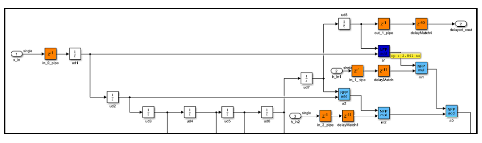
When you click the link to the criticalpathestimated script, the code generator highlights the critical path in the generated model. In the generated model, you see the critical path timing information and blocks that are on this path. This figure shows a section of a Simulink model that has the critical path annotated. The native floating-point operators are highlighted in light blue and the delays are highlighted in orange. The block that is part of the critical path is highlighted in dark blue with the critical path value annotated beside the block. For more information, see Generated Model and Validation Model.
You can clear the highlighting by clicking the link to theclearhighlighting script.
To optimize the critical path, break the critical path by adding pipeline registers. If you select Use Floating Point to use native floating point, set the LatencyStrategy toMax to improve timing. Regenerate the critical path estimation report and the script that highlights the critical path in your design. You can repeat this process until your design timing meets the target frequency that you want.
Characterized Blocks
This table lists blocks that are characterized with fixed-point and single-precision native floating-point types. These blocks are part of the timing database for each supported target device.
Trigonometric Functions
| Simulink Blocks | Fixed-Point Types | Single-Precision Types (Native Floating Point) |
|---|---|---|
| Sin | Not applicable | ✓ |
| Cos | Not applicable | ✓ |
| Tan | Not applicable | ✓ |
| Sincos | Not applicable | ✓ |
| Asin | Not applicable | ✓ |
| Acos | Not applicable | ✓ |
| Atan | Not applicable | ✓ |
| Atan2 | Not applicable | ✓ |
| Sinh | Not applicable | ✓ |
| Cosh | Not applicable | ✓ |
| Tanh | Not applicable | ✓ |
| Atanh | Not applicable | ✓ |
Conversions and Comparisons
Discrete and Signal Routing
HDL Operations and HDL RAMs
Signal Attributes and Lookup Tables
User-Defined Functions
| Simulink Blocks | Fixed-Point Types | Single-Precision Types (Native Floating Point) |
|---|---|---|
| MATLAB Function | Not Applicable | ✓ |
If you have a MATLAB function block in your design and the HDL Block Property Architecture is set to MATLAB Function, when estimating the critical path and generating HDL code, you might see the MATLAB function block appear as an uncharacterized block in the code generation reports. To characterize theMATLAB function block, set the Architecture to MATLAB Datapath.
When you use MATLAB Function blocks and generate code by using theMATLAB Datapath architecture, HDL Coder converts the MATLAB algorithm to a Simulink block diagram in the generated model. In the generated model, critical path estimation can annotate the critical path inside the MATLAB Function block and across the MATLAB Function block boundary with other Simulink blocks. See also HDL Optimizations Across MATLAB Function Block Boundary Using MATLAB Datapath Architecture.
Considerations
Critical Path Estimation for Multirate Models
Critical path estimation does not consider the clock-gating information to different sequential elements in your design.
If your model contains multiple sample rates or uses speed and area optimizations that insert pipeline registers, your design becomes multirate and can have multicycle paths. For multirate models, critical path estimation treats the slow and fast data paths as running at the same rate. A data path that has a faster clock rate might be highlighted as the critical path when the design has another data path at a slower rate. This issue might cause critical path estimation to report inaccurate timing results.
To verify the estimated critical path information, open the HDL Workflow Advisor and run the Generic ASIC/FPGA workflow for your target device to the task.
Critical Path Estimation in Native Floating Point Mode
If you have single data types in your design and you use the Native Floating Point mode by selecting Use Floating Point, the critical path estimation script sometimes highlights a single floating-point operator in the generated model. The code generator highlights a single block because floating-point algorithms are computation-intensive. The critical path can be an internal register-to-register path within the floating-point operator.
In this case, to optimize the critical path timing, set theLatencyStrategy to Max for the Simulink block corresponding to that operator.
Simulink blocks that use half-precision data types do not participate in critical path estimation. These blocks are highlighted by using the 0 ns timing delay.
HDL Code Generation Behavior
When you enable critical path estimation, it is possible that the generated HDL code is different from the report for a Delay block that has an external reset or an enable port. For blocks such as MinMax, the number of generated HDL files might differ when you enable critical path estimation. This change occurs due to certain optimizations performed by the code generator when you enable this optimization. The optimization changes only how the code appears and does not affect the functionality.
Following are the Simulink blocks for which the generated HDL code can potentially be different.
- Delay block that has external reset or enable port
- MinMax
- Unit Delay Enabled Synchronous
- Unit Delay Resettable Synchronous
- Unit Delay Enabled Resettable Synchronous
- Enabled Delay
- Resettable Delay
- Tapped Delay
- Discrete FIR Filter
- Biquad Filter
- MATLAB Function
Inaccuracy in Critical Path Estimation
- Critical path estimation tries to account for routing delays by using an estimation factor. Without running place and route, it is difficult to accurately account for routing delays.
- HDL Coder infers uncharacterized blocks that are combinational in nature as zero-delay combinational blocks. The code generator treats other blocks as registers.
- If your target device does not have timing characteristics that are similar to one of the supported target devices, critical path estimation cannot accurately compute your critical path.
See Also
hdlcoder.FloatingPointTargetConfig | makehdl | genhdltdb | hdlcoder.TimingGenerator