Subsystem - Group blocks to create model hierarchy - Simulink (original) (raw)
Group blocks to create model hierarchy
Libraries:
Simulink / Commonly Used Blocks
Simulink / Ports & Subsystems
HDL Coder / Ports & Subsystems
Alternative Configurations of Subsystem Block:
Atomic Subsystem | Subsystem Reference | Enabled Subsystem | Triggered Subsystem | Enabled and Triggered Subsystem | ...
Description
A Subsystem block contains a subset of blocks within a model or system. The Subsystem block can represent a virtual subsystem or a nonvirtual subsystem.
- Virtual subsystems help visually organize a block diagram. When you group blocks in a virtual subsystem or expand a virtual subsystem, you can affect the execution order of blocks because of the changes to the block paths. Virtual subsystems are neither conditionally nor atomically executed. Virtual subsystems do not have checksums.
- Nonvirtual subsystems, also known as atomic subsystems, help functionally organize a block diagram. When you group blocks in a nonvirtual subsystem or expand a nonvirtual subsystem, you change the model behavior. Each nonvirtual subsystem executes as a single block, or atomic unit, when the parent model executes. The blocks in a nonvirtual subsystem execute consecutively.
For information on the types of nonvirtual subsystems, see Explore Types of Subsystems.
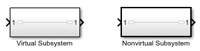
To determine whether a subsystem is virtual or nonvirtual, use either of these strategies:
- Check the border of the block. A block that represents a virtual subsystem has a thin border. A block that represents a nonvirtual subsystem has a thick border.
- Use the get_param function to query the Boolean block parameter
IsSubsystemVirtual.
The ports on a Subsystem block correspond to blocks inside the subsystem. For more information, see Connect Subsystems.
The Subsystem block supports signal label propagation through subsystemInport and Outport blocks. For more information, see Signal Label Propagation.
Examples
You can create a subsystem by adding a Subsystem block, then adding contents to the subsystem.
Insert a Subsystem block into your model.
For example:
- Open the quick-insert menu by double-clicking the Simulink® canvas.
- In the search box, start typing the name of the block. For example, type
subsystem. - In the list that appears, select the block for the type of subsystem that you want to implement in your model. Use the arrow keys and pressEnter or click the block.
To view or edit the contents of a subsystem, double-click theSubsystem block. To exit the subsystem, below the left end of the Simulink Toolbar, click the Back button  . For more information on how to navigate the hierarchy of a model with subsystems, see Navigate Model Hierarchy.
You can create a subsystem by converting part of an existing model into a subsystem.
In the Simulink canvas, drag a selection box over the model elements that you want to include in the subsystem. An ellipsis appears next to the selection box.

Pause on the ellipsis. An action bar expands.
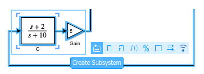
In the action bar, click Create Subsystem or another subsystem option.

To provide an interface for signals entering and leaving the subsystem, theSubsystem block contains blocks that correspond to input and output ports.
When the selection contains blocks that correspond to input and output ports, the new subsystem includes copies of those blocks. The new subsystem does not contain copies of blocks that correspond to control ports.
To replace a Subsystem block with its contents, you can expand the subsystem.
Select the Subsystem block. Then, in the Simulink Toolstrip, on the Subsystem Block tab, clickExpand.
The contents of the subsystem appear in an area labeled with the name of the replaced block.

For more information, see Expand Subsystem Contents.
To determine whether a subsystem is virtual, use the get_param function with the Boolean block parameter IsSubsystemVirtual.
Open the example. Then, open the SubsystemExecution model.
open_system("SubsystemExecution");
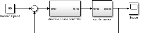
Check whether the Subsystem block named discrete cruise controller is virtual.
get_param("SubsystemExecution/discrete cruise controller",... "IsSubsystemVirtual")
This subsystem is nonvirtual. The thick border of the block icon indicates that the subsystem is nonvirtual.
Check whether the Subsystem block named car dynamics is virtual.
get_param("SubsystemExecution/car dynamics","IsSubsystemVirtual")
This subsystem is virtual.
Extended Examples
Ports
Input
Placing a block such as an Inport or In Bus Element block in a subsystem adds an external input port to the Subsystem block.
Use Inport or In Bus Element blocks to get signals from the local environment.
For more information, see Connect Subsystems.
Data Types: half | single | double | int8 | int16 | int32 | int64 | uint8 | uint16 | uint32 | uint64 | Boolean | fixed point | enumerated | bus | image
Complex Number Support: Yes
A reinitialize event port provides a function-call control signal that triggers a subsystem reinitialize event, which resets the states of the subsystem.
For versions prior to R2025a, the subsystem must contain a Reinitialize Function block that corresponds to each subsystem reinitialize event. To specify the port name, use theEvent name parameter of the Event Listener block in the Reinitialize Function block. For more information, see Reinitialize States of Blocks in Subsystem.
Note
Starting in R2025a, you no longer need to place a Reinitialize Function block inside an atomic subsystem to display its reinitialize event port.
Dependencies
To enable this type of port, select Treat as atomic unit, and then select Show subsystem reinitialize ports.
Output
Placing a block such as an Outport or Out Bus Element block in a subsystem adds an output port from theSubsystem block.
Use Outport or Out Bus Element blocks to send signals to the local environment.
For more information, see Connect Subsystems.
Data Types: half | single | double | int8 | int16 | int32 | int64 | uint8 | uint16 | uint32 | uint64 | Boolean | fixed point | enumerated | bus | image
Complex Number Support: Yes
Parameters
To edit block parameters interactively, use theProperty Inspector. From the Simulink Toolstrip, on the Simulation tab, in thePrepare gallery, select Property Inspector.
Main
Select how to display port labels on the Subsystem block icon.
none— Do not display port labels.FromPortIcon— If the corresponding port icon displays a signal name, display the signal name on the Subsystem block. Otherwise, display the port block name or the port number if the block name is a default name.FromPortBlockName— Display the name of the corresponding port block on the Subsystem block.SignalName— If the signal connected to the port is named, display the name of the signal on the Subsystem block. Otherwise, display the name of the corresponding port block.
For port label editing on Subsystem blocks, see Edit Port Labels on Subsystem Blocks.
Programmatic Use
To set the block parameter value programmatically, use the set_param function.
| Parameter: | ShowPortLabels | ||
|---|---|---|---|
| Values: | 'FromPortIcon' (default) | 'FromPortBlockName' | 'SignalName' | 'none' |
Control user access to the contents of the subsystem.
ReadWrite— Enable opening and modification of subsystem contents.ReadOnly— Enable opening but not modification of the subsystem. If the subsystem resides in a block library, you can create and open links to the subsystem and can make and modify local copies of the subsystem but cannot change the permissions or modify the contents of the original library instance.NoReadOrWrite— Disable opening or modification of subsystem. If the subsystem resides in a library, you can create links to the subsystem in a model but cannot open, modify, change permissions, or create local copies of the subsystem.
You do not receive a response if you attempt to view the contents of a subsystem whose Read/Write permissions parameter is set to NoReadOrWrite. For example, when double-clicking such a subsystem, the software does not open the subsystem and does not display any messages.
Programmatic Use
To set the block parameter value programmatically, use the set_param function.
| Parameter: | Permissions | |
|---|---|---|
| Values: | 'ReadWrite' (default) | 'ReadOnly' | 'NoReadOrWrite' |
Enter the name of a function to be called if an error occurs while the software executes the subsystem.
The software passes two arguments to the function: the handle of the subsystem and a character vector that specifies the error type. If no function is specified, the software displays a generic error message if executing the subsystem causes an error.
Programmatic Use
To set the block parameter value programmatically, use the set_param function.
| Parameter: | ErrorFcn |
|---|---|
| Values: | '' (default) | function name in quotes |
| Data Types: | char | string |
Select whether to resolve names of workspace variables referenced by this subsystem.
For more information, see Symbol Resolution and Symbol Resolution Process.
All— Resolve all names of workspace variables used by this subsystem, including those used to specify block parameter values and Simulink data objects (for example, Simulink.Signal objects).ExplicitOnly— Resolve only names of workspace variables used to specify block parameter values, data store memory (where no block exists), signals, and states marked as “must resolve”.None— Do not resolve any workspace variable names.
Programmatic Use
To set the block parameter value programmatically, use the set_param function.
| Parameter: | PermitHierarchicalResolution | |
|---|---|---|
| Values: | 'All' (default) | 'ExplicitOnly' | 'None' |
Selecting this parameter causes the software to treat the subsystem as a unit when determining the execution order of block methods.
off— Treat all blocks in the subsystem as being at the same level in the model hierarchy as the subsystem when determining block method execution order. This can cause execution of methods of blocks in the subsystem to be interleaved with execution of methods of blocks outside the subsystem.on— Treat the subsystem as a unit when determining the execution order of block methods. For example, when it needs to compute the output of the subsystem, the software invokes the output methods of all the blocks in the subsystem before invoking the output methods of other blocks at the same level as the Subsystem block.
The default value depends on the block configuration. For example, the default value for the Subsystem block is off. The default value for the Atomic Subsystem block is on.
Programmatic Use
To set the block parameter value programmatically, use the set_param function.
| Parameter: | TreatAsAtomicUnit |
|---|---|
| Values: | 'off' | 'on' |
Select this parameter to display the reinitialize event ports. Clear this parameter to remove the ports.
Dependencies
To enable this parameter, select Treat as atomic unit.
Programmatic Use
To set the block parameter value programmatically, use the set_param function.
| Parameter: | ShowSubsystemReinitializePorts |
|---|---|
| Values: | 'off' (default) | 'on' |
Try to eliminate any artificial algebraic loops that include the atomic subsystem
off— Do not try to eliminate any artificial algebraic loops that include the atomic subsystem.on— Try to eliminate any artificial algebraic loops that include the atomic subsystem.
Dependencies
To enable this parameter, select Treat as atomic unit.
Programmatic Use
To set the block parameter value programmatically, use the set_param function.
| Parameter: | MinAlgLoopOccurrences |
|---|---|
| Values: | 'off' (default) | 'on' |
Specify how to schedule the subsystem.
Sample time— Specify whether all blocks in this subsystem must run at the same rate or can run at different rates.Periodic partition— Schedule the subsystem as a periodic partition. Specify a partition name and a sample time corresponding to the rate at which the partition runs.Aperiodic partition— Schedule the subsystem as an aperiodic partition. Specify a partition name.
Dependencies
To enable this parameter, select Treat as atomic unit.
Programmatic Use
To set the block parameter value programmatically, use the set_param function.
| Parameter: | ScheduleAs | |
|---|---|---|
| Values: | 'Sample time' (default) | 'Periodic partition' | 'Aperiodic partition' |
Specify the name of the partition for the subsystem.
Dependencies
To enable this parameter, select Treat as atomic unit and setSchedule as to Periodic partition orAperiodic partition.
Programmatic Use
To set the block parameter value programmatically, use the set_param function.
| Parameter: | PartitionName |
|---|---|
| Values: | '' (default) | partition name in quotes |
| Data Types: | char | string |
Specify whether all blocks in this subsystem must run at the same rate or can run at different rates.
-1— Inherited sample time.[Ts 0]— Periodic sample time.
If the blocks in the subsystem can run at different rates, specify the subsystem sample time as inherited (-1).
If all blocks must run at the same rate, specify the sample time corresponding to this rate as the value of the Sample time parameter.
If any of the blocks in the subsystem specify a different sample time (other than-1 or inf), the software displays an error message when you update or simulate the model. For example, suppose all the blocks in the subsystem must run 5 times a second. To ensure this rate, specify the sample time of the subsystem as 0.2. In this example, if any of the blocks in the subsystem specify a sample time other than 0.2, -1, orinf, the software displays an error when you update or simulate the model.
Dependencies
To enable this parameter, select Treat as atomic unit.
Programmatic Use
To set the block parameter value programmatically, use the set_param function.
| Parameter: | SystemSampleTime |
|---|---|
| Values: | '-1' (default) | '[Ts 0]' |
Specify whether the software treats the subsystem as a unit when propagating variant conditions from Variant Source blocks or to Variant Sink blocks.
on— The software treats the subsystem as a unit when propagating variant conditions from Variant Source blocks or to Variant Sink blocks. For example, when the software computes the variant condition of the subsystem, the software propagates that condition to all the blocks in the subsystem.off— The software treats all blocks in the subsystem as being at the same level in the model hierarchy as the subsystem itself when determining their variant condition.
Programmatic Use
To set the block parameter value programmatically, use the set_param function.
| Parameter: | TreatAsGroupedWhenPropagatingVariantConditions |
|---|---|
| Values: | 'on' (default) | 'off' |
Dependencies
To enable this parameter, clear the Treat as atomic unit parameter.
Code Generation
Parameters on the Code Generation tab require a Simulink Coder™ or Embedded Coder® license.
Select the code format to be generated for an atomic (nonvirtual) subsystem.
Auto— The software chooses the optimal format for you based on the type and number of instances of the subsystem that exist in the model.Inline— The software inlines the subsystem unconditionally.Nonreusable function— If Filename options is set toAuto, the software packages separate functions in the model file. If File name options is set toUse subsystem name,Use function name, orUser specifiedusing different filenames, the software packages separate functions in separate files.
Subsystems with this setting generate functions that might have arguments depending on the Function interface parameter setting. You can name the generated function and file using parameters Function name and File name (no extension), respectively. These functions are not reentrant.Reusable function— The software generates a function with arguments that allows reuse of subsystem code when a model includes multiple instances of the subsystem.
This option also generates a function with arguments that allows subsystem code to be reused in the generated code of a model reference hierarchy that includes multiple instances of a subsystem across referenced models. In this case, the subsystem must be in a library.
For more information, see:
- Generate Code and Executables for Individual Subsystems (Simulink Coder)
- Generate Inlined Subsystem Code (Simulink Coder)
- Generate Subsystem Code as Separate Function and Files (Simulink Coder)
- Generate Reusable Code from Library Subsystems Shared Across Models (Simulink Coder)
The default value depends on the block configuration. For example, the default value for the Subsystem block is Auto. The default value for the CodeReuseSubsystem block isReusable function.
Tips
- When you want multiple instances of a subsystem to be represented as one reusable function, you can designate each one of them as
Autoor asReusable function. Using one or the other is best, as using both creates two reusable functions, one for each designation. The outcomes of these choices differ only when reuse is not possible. SelectingAutodoes not allow control of the function or filename for the subsystem code. - The
Reusable functionandAutooptions both try to determine if multiple instances of a subsystem exist and if the code can be reused. The difference between the behavior of each option is that when reuse is not possible:Autoyields inlined code, or if circumstances prohibit inlining, separate functions for each subsystem instance.Reusable functionyields a separate function with arguments for each subsystem instance in the model.
- If you select
Reusable functionwhile your generated code is under source control, set File name options toUse subsystem name,Use function name, orUser specified. Otherwise, the names of your code files change whenever you modify your model, which prevents source control on your files. - If you select an option other than
AutoorInlineand the model configuration parameterStates, the code generator produces separate output and update methods. The code generator does not take into account theCombine output and update methods for code generation and simulation specification.
Dependencies
- This parameter requires a Simulink Coder license for code generation.
- To enable this parameter, select Treat as atomic unit.
Programmatic Use
To set the block parameter value programmatically, use the set_param function.
| Parameter: | RTWSystemCode | ||
|---|---|---|---|
| Values: | 'Auto' | 'Inline' | 'Nonreusable function' | 'Reusable function' |
Select how the software names the function it generates for the subsystem.
If you have an Embedded Coder license, you can control function names with options on the Configuration Parameter > pane.
Auto— Assign a unique function name using the default naming convention,_`model`__ _`subsystem`_(), wheremodelis the name of the model and_subsystem_ is the name of the subsystem, or that of an identical one when code is being reused.
If you selectReusable functionfor theFunction packaging parameter and a model reference hierarchy contains multiple instances of the reusable subsystem, in order to generate reusable code for the subsystem, Function name options must be set toAuto.Use subsystem name— Use the subsystem name as the function name. By default, the function name uses the naming convention_`model`__ _`subsystem`_.
When a subsystem is in a library block and the subsystem parameter Function packaging is set toReusable function, if you set theUse subsystem nameoption, the code generator uses the name of the library block for the subsystem function name and filename.User specified— Enable the Function name field. Enter any legal C or C++ function name, which must be unique.
For more information, see Generate Subsystem Code as Separate Function and Files (Simulink Coder).
The default value depends on the block configuration. For example, the default value for the Subsystem block is Auto. The default value for the CodeReuseSubsystem block isUse subsystem name.
Dependencies
- This parameter requires a Simulink Coder license.
- To enable this parameter, set Function packaging to
Nonreusable functionorReusable function.
Programmatic Use
To set the block parameter value programmatically, use the set_param function.
| Parameter: | RTWFcnNameOpts | |
|---|---|---|
| Values: | 'Auto' | 'Use subsystem name' | 'User specified' |
Specify a unique, valid C or C++ function name for subsystem code.
Use this parameter if you want to give the function a specific name instead of allowing the Simulink Coder code generator to assign its own autogenerated name or use the subsystem name. For more information, see Generate Subsystem Code as Separate Function and Files (Simulink Coder).
Dependencies
- This parameter requires a Simulink Coder license.
- To enable this parameter, set Function name options to
User specified.
Programmatic Use
To set the block parameter value programmatically, use the set_param function.
| Parameter: | RTWFcnName |
|---|---|
| Values: | '' (default) | function name in quotes |
| Data Types: | char | string |
Select how the software names the separate file for the function it generates for the subsystem.
Auto— Depending on the configuration of the subsystem and how many instances are in the model,Autoyields different results.- If the code generator does not generate a separate file for the subsystem, the subsystem code is generated within the code module generated from the subsystem parent system. If the subsystem parent is the model itself, the subsystem code is generated within
_`model`_.cor_`model`_.cpp. - If you select
Reusable functionfor theFunction packaging parameter and your generated code is under source control, consider specifying a File name options value other thanAuto. This prevents the generated filename from changing due to unrelated model modifications, which is problematic for using source control to manage configurations. - If you select
Reusable functionfor theFunction packaging parameter and a model reference hierarchy contains multiple instances of the reusable subsystem, in order to generate reusable code for the subsystem, File name options must be set toAuto.
- If the code generator does not generate a separate file for the subsystem, the subsystem code is generated within the code module generated from the subsystem parent system. If the subsystem parent is the model itself, the subsystem code is generated within
Use subsystem name— The code generator generates a separate file, using the subsystem (or library block) name as the filename.
When File name options is set toUse subsystem name, the subsystem filename is mangled if the model containsModel blocks, or if a model reference target is being generated for the model. In these situations, the filename for the subsystem consists of the subsystem name prefixed by the model name.Use function name— The code generator uses the function name specified by Function name options as the filename.User specified— This option enables theFile name (no extension) text entry field. The code generator uses the name you enter as the filename. Enter any filename, but do not include the.cor.cpp(or any other) extension. This filename need not be unique.
While a subsystem source filename need not be unique, you must avoid giving nonunique names that result in cyclic dependencies. For example,sys_a.hincludessys_b.h,sys_b.hincludessys_c.h, andsys_c.hincludessys_a.h.
The default value depends on the block configuration. For example, the default value for the Subsystem block is Auto. The default value for the CodeReuseSubsystem block isUse function name.
Dependencies
- This parameter requires a Simulink Coder license.
- To enable this parameter, set Function packaging to
Nonreusable functionorReusable function.
Programmatic Use
To set the block parameter value programmatically, use the set_param function.
| Parameter: | RTWFileNameOpts | ||
|---|---|---|---|
| Values: | 'Auto' | 'Use subsystem name' | 'Use function name' | 'User specified' |
The filename that you specify does not have to be unique. However, avoid giving non-unique names that result in cyclic dependencies. For example,sys_a.h includes sys_b.h,sys_b.h includes sys_c.h, andsys_c.h includes sys_a.h.
For more information, see Generate Subsystem Code as Separate Function and Files (Simulink Coder).
Dependencies
- This parameter requires a Simulink Coder license.
- To enable this parameter, set File name options to
User specified.
Programmatic Use
To set the block parameter value programmatically, use the set_param function.
| Parameter: | RTWFileName |
|---|---|
| Values: | '' (default) | filename in quotes |
| Data Types: | char | string |
Select how to use arguments with the generated function.
void_void— Generate a function without arguments and pass data as global variables. For example:
void subsystem_function(void)Allow arguments (Optimized)— Generate a function that uses arguments instead of passing data as global variables. This specification reduces global RAM. This option might reduce code size and improve execution speed and enable the code generator to apply additional optimizations. For example:
void subsystem_function(real_T rtu_In1, real_T rtu_In2,
real_T *rty_Out1)
In some cases, when generating optimized code, the code generator might not generate a function that has arguments.
Allow arguments (Match graphical interface)— Generate a function interface that uses arguments that match the Subsystem graphical block interface. The generated function interface is predictable and does not change. A predictable interface can be useful for debugging and testing your code and integrating with external applications. For example, if a model has twoInport blocks and two Outport blocks, then the generated function interface is:
void subsystem_function(real_T rtu_In1, real_T rtu_In2,
real_T *rty_Out1, real_T *rty_Out2)
For more information, see:
- Reduce Global Variables in Nonreusable Subsystem Functions (Embedded Coder)
- Generate Predictable Function Interface to Match Graphical Block Interface (Embedded Coder)
- Generate Modular Function Code for Nonvirtual Subsystems (Embedded Coder)
Dependencies
- This parameter requires an Embedded Coder license and an ERT-based system target file.
- To enable this parameter, set Function packaging to
Nonreusable function.
Programmatic Use
To set the block parameter value programmatically, use the set_param function.
| Parameter: | FunctionInterfaceSpec | |
|---|---|---|
| Values: | 'void_void' (default) | 'Allow arguments (Optimized)' | 'Allow arguments (Match graphical interface)' |
Generate subsystem function code in which the internal data for an atomic subsystem is separated from its parent model and is owned by the subsystem.
off— Do not generate subsystem function code in which the internal data for an atomic subsystem is separated from its parent model and is owned by the subsystem.on— Generate subsystem function code in which the internal data for an atomic subsystem is separated from its parent model and is owned by the subsystem. The subsystem data structure is declared independently from the parent model data structures. A subsystem with separate data has its own block I/O andDWorkdata structure. As a result, the generated code for the subsystem is easier to trace and test. The data separation also tends to reduce the maximum size of global data structures throughout the model, because they are split into multiple data structures.
For details on how to generate modular function code for an atomic subsystem, seeGenerate Modular Function Code for Nonvirtual Subsystems (Embedded Coder).
For details on how to apply memory sections to atomic subsystems, see Override Default Memory Placement for Subsystem Functions and Data (Embedded Coder).
Dependencies
- This parameter requires an Embedded Coder license and an ERT-based system target file.
- To enable this parameter, set Function packaging to
Nonreusable function.
Programmatic Use
To set the block parameter value programmatically, use the set_param function.
| Parameter: | FunctionWithSeparateData |
|---|---|
| Values: | 'off' (default) | 'on' |
Select how the software applies memory sections to the subsystem initialization and termination functions.
Inherit from model— Apply the root model memory sections to the subsystem function code.Default— Do not apply memory sections to the subsystem system code, overriding any model-level specification.- Apply one of the model memory sections to the subsystem.
Tips
- The possible values vary depending on what, if any, package of memory sections you have set for the model configuration. See Control Data and Function Placement in Memory by Inserting Pragmas (Embedded Coder) and Model Configuration Parameters: Code Generation (Simulink Coder).
- If you have not configured the model with a package,
Inherit from modelis the only available value. Otherwise, the list includesDefaultand all memory sections the model package contains. - These options can be useful for overriding the model memory section settings for the given subsystem. For details on how to apply memory sections to atomic subsystems, see Override Default Memory Placement for Subsystem Functions and Data (Embedded Coder).
Dependencies
- This parameter requires an Embedded Coder license and an ERT-based system target file.
- To enable this parameter, set Function packaging to
Nonreusable functionorReusable function.
Programmatic Use
To set the block parameter value programmatically, use the set_param function.
| Parameter: | RTWMemSecFuncInitTerm | |
|---|---|---|
| Values: | 'Inherit from model' (default) | 'Default' | model memory section in quotes |
Select how Embedded Coder applies memory sections to the subsystem execution functions.
Inherit from model— Apply the root model memory sections to the subsystem function code.Default— Do not apply memory sections to the subsystem system code, overriding any model-level specification.- Apply one of the model memory sections to the subsystem.
Tips
- The possible values vary depending on what, if any, package of memory sections you have set for the model configuration. See Control Data and Function Placement in Memory by Inserting Pragmas (Embedded Coder) and Model Configuration Parameters: Code Generation (Simulink Coder).
- If you have not configured the model with a package,
Inherit from modelis the only available value. Otherwise, the list includesDefaultand all memory sections the model package contains. - These options can be useful for overriding the model memory section settings for the given subsystem. For details on how to apply memory sections to atomic subsystems, see Override Default Memory Placement for Subsystem Functions and Data (Embedded Coder).
Dependencies
- This parameter requires an Embedded Coder license and an ERT-based system target file.
- To enable this parameter, set Function packaging to
Nonreusable functionorReusable function.
Programmatic Use
To set the block parameter value programmatically, use the set_param function.
| Parameter: | RTWMemSecFuncExecute | |
|---|---|---|
| Values: | 'Inherit from model' (default) | 'Default' | model memory section in quotes |
Select how the software applies memory sections to the subsystem constants.
Inherit from model— Apply the root model memory sections to the subsystem data.Default— Do not apply memory sections to the subsystem data, overriding any model-level specification.- Apply one of the model memory sections to the subsystem.
Tips
- The memory section that you specify applies to the corresponding global data structures in the generated code. For basic information about the global data structures generated for atomic subsystems, see Standard Data Structures (Simulink Coder).
- The possible values vary depending on what, if any, package of memory sections you have set for the model configuration. See Control Data and Function Placement in Memory by Inserting Pragmas (Embedded Coder).
- If you have not configured the model with a package,
Inherit from modelis the only available value. Otherwise, the list includesDefaultand all memory sections the model package contains. - These options can be useful for overriding the model memory section settings for the given subsystem. For details on how to apply memory sections to atomic subsystems, see Override Default Memory Placement for Subsystem Functions and Data (Embedded Coder).
Dependencies
- This parameter requires an Embedded Coder license and an ERT-based system target file.
- To enable this parameter, set Function packaging to
Nonreusable functionand select theFunction with separate data parameter.
Programmatic Use
To set the block parameter value programmatically, use the set_param function.
| Parameter: | RTWMemSecDataConstants | |
|---|---|---|
| Values: | 'Inherit from model' (default) | 'Default' | model memory section in quotes |
Select how the software applies memory sections to the subsystem internal data.
Inherit from model— Apply the root model memory sections to the subsystem data.Default— Do not apply memory sections to the subsystem data, overriding any model-level specification.- Apply one of the model memory sections to the subsystem.
Tips
- The memory section that you specify applies to the corresponding global data structures in the generated code. For basic information about the global data structures generated for atomic subsystems, see Standard Data Structures (Simulink Coder).
- The possible values vary depending on what, if any, package of memory sections you have set for the model configuration. See Control Data and Function Placement in Memory by Inserting Pragmas (Embedded Coder).
- If you have not configured the model with a package,
Inherit from modelis the only available value. Otherwise, the list includesDefaultand all memory sections the model package contains. - These options can be useful for overriding the model memory section settings for the given subsystem. For details on how to apply memory sections to atomic subsystems, see Override Default Memory Placement for Subsystem Functions and Data (Embedded Coder).
Dependencies
- This parameter requires an Embedded Coder license and an ERT-based system target file.
- To enable this parameter, set Function packaging to
Nonreusable functionand select theFunction with separate data parameter.
Programmatic Use
To set the block parameter value programmatically, use the set_param function.
| Parameter: | RTWMemSecDataInternal | |
|---|---|---|
| Values: | 'Inherit from model' (default) | 'Default' | model memory section in quotes |
Select how the software applies memory sections to the subsystem parameters.
Inherit from model— Apply the root model memory sections to the subsystem function code.Default— Do not apply memory sections to the subsystem system code, overriding any model-level specification.- Apply one of the model memory sections to the subsystem.
Tips
- The memory section that you specify applies to the corresponding global data structure in the generated code. For basic information about the global data structures generated for atomic subsystems, see Standard Data Structures (Simulink Coder).
- The possible values vary depending on what, if any, package of memory sections you have set for the model configuration. See Control Data and Function Placement in Memory by Inserting Pragmas (Embedded Coder).
- If you have not configured the model with a package,
Inherit from modelis the only available value. Otherwise, the list includesDefaultand all memory sections the model package contains. - These options can be useful for overriding the model memory section settings for the given subsystem. For details on how to apply memory sections to atomic subsystems, see Override Default Memory Placement for Subsystem Functions and Data (Embedded Coder).
Dependencies
- This parameter requires an Embedded Coder license and an ERT-based system target file.
- To enable this parameter, set Function packaging to
Nonreusable functionand select theFunction with separate data parameter.
Programmatic Use
To set the block parameter value programmatically, use the set_param function.
| Parameter: | RTWMemSecDataParameters | |
|---|---|---|
| Values: | 'Inherit from model' (default) | 'Default' | model memory section in quotes |
Subsystem Reference
Specify the subsystem file you want to reference. For information about subsystem references, see Create and Use Referenced Subsystems in Models.
Dependencies
To access this parameter, in the Subsystem Reference section, click Convert.
For more information on how to convert a subsystem to a referenced subsystem, see Convert Subsystem to a Referenced Subsystem.
Programmatic Use
To set the block parameter value programmatically, use the set_param function.
| Parameter: | ReferencedSubsystem |
|---|---|
| Values: | '' (default) | subsystem filename in quotes |
| Data Types: | char | string |
Block Characteristics
| Data Types | Booleana | busa | doublea | enumerateda | fixed pointa | halfa | imagea | integera | singlea | stringa |
|---|---|---|---|---|---|---|---|---|---|
| Direct Feedthrough | no | ||||||||
| Multidimensional Signals | yesa | ||||||||
| Variable-Size Signals | yesa | ||||||||
| Zero-Crossing Detection | no | ||||||||
| a Actual data type or capability support depends on block implementation. |
Alternative Configurations
The Atomic Subsystem block selects the Treat as atomic unit parameter.
Libraries:
Simulink / Ports & Subsystems
HDL Coder / Ports & Subsystems
Libraries:
Simulink / Ports & Subsystems
Libraries:
Simulink / Ports & Subsystems
HDL Coder / Ports & Subsystems
The Triggered Subsystem is a template that contains a Trigger block with Trigger type set torising.
Libraries:
Simulink / Ports & Subsystems
HDL Coder / Ports & Subsystems
The Enabled and Triggered Subsystem is a template that contains an Enable block and a Trigger block with Trigger type set torising.
Libraries:
Simulink / Ports & Subsystems
Libraries:
Simulink / Ports & Subsystems
The If Action Subsystem is a template for creating a subsystem whose execution is controlled by an If block. The subsystem contains an Action Port block.
Libraries:
Simulink / Ports & Subsystems
The Switch Case Action Subsystem is a template for creating a subsystem whose execution is controlled by a Switch Case block. The subsystem contains an Action Port block.
Libraries:
Simulink / Ports & Subsystems
The Function-Call Subsystem is a template that contains a Trigger block with Trigger type set tofunction-call.
Libraries:
Simulink / Ports & Subsystems
Libraries:
Simulink / Ports & Subsystems
Libraries:
Simulink / Ports & Subsystems
Libraries:
Simulink / Ports & Subsystems
HDL Coder / Ports & Subsystems
Since R2022a
The Message Polling Subsystem is a template that contains a Trigger block withTrigger type set to message andTrigger time set to on sample time hit. The Trigger block replaces the Inport block.
Libraries:
Simulink / Messages & Events
Since R2022a
The Message Triggered Subsystem is a template that contains a Trigger block withTrigger type set to message andTrigger time set to on message available. The Trigger block replaces theInport block.
Libraries:
Simulink / Messages & Events
The CodeReuseSubsystem block selects the Treat as atomic unit parameter and sets Function packaging toReusable function.
Libraries:
Simulink / Ports & Subsystems
Since R2022b
Libraries:
Simulink / Matrix Operations
Tips
- A signal viewing subsystem is an atomic subsystem that encapsulates processing and viewing of signals received from the target system in External mode. To specify an atomic subsystem as a signal viewing subsystem, set
SimViewingDeviceto'on'. For more information, see Signal Viewing Subsystems (Simulink Coder).
Extended Capabilities
Actual code generation support depends on block implementation.
HDL Coder™ provides additional configuration options that affect HDL implementation and synthesized logic.
HDL Architecture
| Architecture | Description |
|---|---|
| Module (default) | Generate code for the subsystem and the blocks within the subsystem. |
| BlackBox | Generate a black box interface. The generated HDL code includes only the input/output port definitions for the subsystem. Therefore, you can use a subsystem in your model to generate an interface to existing, manually written HDL code. The black-box interface generation for subsystems is similar to the Model block interface generation without the clock signals. |
| No HDL | Remove the subsystem from the generated code. You can use the subsystem in simulation, however, treat it as a “no-op” in the HDL code. |
HDL Block Properties
| General | |
|---|---|
| AdaptivePipelining | Automatic pipeline insertion based on the synthesis tool, target frequency, and multiplier word-lengths. The default is inherit. See alsoAdaptivePipelining (HDL Coder). |
| ClockRatePipelining | Insert pipeline registers at a faster clock rate instead of the slower data rate. The default is inherit. See also ClockRatePipelining (HDL Coder). |
| ConstrainedOutputPipeline | Number of registers to place at the outputs by moving existing delays within your design. Distributed pipelining does not redistribute these registers. The default is0. For more details, see ConstrainedOutputPipeline (HDL Coder). |
| DistributedPipelining | Pipeline register distribution, or register retiming. The default is inherit. See also DistributedPipelining (HDL Coder). |
| DSPStyle | Synthesis attributes for multiplier mapping. The default is none. See also DSPStyle (HDL Coder). |
| FlattenHierarchy | Remove subsystem hierarchy from generated HDL code. The default is inherit. See also FlattenHierarchy (HDL Coder). |
| InputPipeline | Number of input pipeline stages to insert in the generated code. Distributed pipelining and constrained output pipelining can move these registers. The default is0. For more details, see InputPipeline (HDL Coder). |
| OutputPipeline | Number of output pipeline stages to insert in the generated code. Distributed pipelining and constrained output pipelining can move these registers. The default is0. For more details, see OutputPipeline (HDL Coder). |
| SharingFactor | Number of functionally equivalent resources to map to a single shared resource. The default is 0. See also Resource Sharing (HDL Coder). |
| StreamingFactor | Number of parallel data paths, or vectors, that are time multiplexed to transform into serial, scalar data paths. The default is 0, which implements fully parallel data paths. See also Streaming (HDL Coder). |
If this block is not the DUT, the block property settings in the Target Specification tab are ignored. In the HDL Workflow Advisor, if you use theIP Core Generation workflow, these target specification block property values are saved with the model. If you specify these target specification block property values using hdlset_param, when you open HDL Workflow Advisor, the fields are populated with the corresponding values.
| Target Specification | |
|---|---|
| AdditionalTargetInterfaces | Additional target interfaces, specified as a character vector. To save this block property on the model, in the Set Target Interface task of the IP Core Generation workflow, corresponding to the DUT ports that you want to add more interfaces, select Add more.... You can then add more interfaces in the Add New Target Interfaces dialog box. Specify the type of interface, number of additional interfaces, and a unique name for each additional interface. Values: '' (default) | cell array of character vectors Example:'{{'AXI4-Stream','InterfaceID','AXI4-Stream1'}}' |
| ProcessorFPGASynchronization | Processor/FPGA synchronization mode, specified as a character vector. To save this block property on the model, specify the Processor/FPGA Synchronization in the Set Target Interface task of the IP Core Generation workflow.Values: Free running (default) | Coprocessing - blockingExample: 'Free running' |
| TestPointMapping | To save this block property on the model, specify the mapping of test point ports to target platform interfaces in the Set Target Interface task of the IP Core Generation workflow.Values: '' (default) | cell array of character vectorsExample: '{{'TestPoint','AXI4-Lite','x"108"'}}' |
| TunableParameterMapping | To save this block property on the model, specify the mapping of tunable parameter ports to target platform interfaces in the Set Target Interface task of the IP Core Generation workflow.Values: '' (default) | cell array of character vectorsExample: '{{'myParam','AXI4-Lite','x"108"'}}' |
| AXI4RegisterReadback | To save this block property on the model, specify whether you want to enable readback on AXI4 subordinate write registers in the Generate RTL Code and IP Core task of the IP Core Generation workflow. To learn more, see Model Design for AXI4 Slave Interface Generation (HDL Coder).Values: 'off' (default) |'on' |
| AXI4SlaveIDWidth | To save this block property on the model, specify the number of AXI manager interfaces that you want to connect the DUT IP core to by using the AXI4 Slave ID Width setting in the Generate RTL Code and IP Core task of the IP Core Generation workflow. To learn more, see Define Multiple AXI Master Interfaces in Reference Designs to Access DUT AXI4 Slave Interface (HDL Coder). Values: 'off' (default) |'on' |
| RegisterInterfaceReadPipeline | To save this block property on the model, Specify the number of pipeline stages to insert in the read address decoder path by using theRegister interface read pipeline setting in the Generate RTL Code and IP Core task of the IP Core Generation workflow. To learn more, see Model Design for AXI4 Slave Interface Generation (HDL Coder). Values: 0 (default) | character vector |
| GenerateDefaultAXI4Slave | To save this block property on the model, specify whether you want to disable generation of default AXI4 subordinate interfaces in the Generate RTL Code and IP Core task of the IP Core Generation workflow.Values: 'on' (default) |'off' |
| IPCoreAdditionalFiles | Verilog®, SystemVerilog, or VHDL® files for black boxes in your design. Specify the full path to each file, and separate file names with a semicolon (;).You can set this property in the HDL Workflow Advisor, in the Additional source files field.Values: '' (default) | character vectorExample: 'C:\myprojfiles\led_blinking_file1.vhd;C:\myprojfiles\led_blinking_file2.vhd;' |
| IPCoreName | IP core name, specified as a character vector.You can set this property in the HDL Workflow Advisor, in the IP core name field. If this property is set to the default value, the HDL Workflow Advisor constructs the IP core name based on the name of the DUT.Values: '' (default) | character vectorExample: 'my_model_name' |
| IPCoreVersion | IP core version number, specified as a character vector.You can set this property in the HDL Workflow Advisor, in the IP core version field. If this property is set to the default value, the HDL Workflow Advisor sets the IP core version.Values: '' (default) | character vectorExample: '1.3' |
| IPDataCaptureBufferSize | FPGA Data Capture buffer size, specified as a character vector. Use FPGA Data Capture to observe signals in a design when running on an FPGA. The buffer size uses values that are 128*2^n, where n is an integer. By default, the buffer size is 128 (n=0). The maximum value of n is 13, which means that the maximum value for buffer size is 1048576 (=128*2^13). Values: '' (default) | character vector Example: '1.3' |
Generate HDL Code with Algebraic Loops
To generate HDL code for models that contain Subsystem blocks:
- In the Configuration Parameters dialog box, click , and set the parameter to
noneorwarning. - Open the block mask for the Subsystem block and select the and parameters.
Subsystem must be atomic to support PLC code generation.
PLC Block Properties
| UseExternalDefinition | Suppress block definition in generated code. The default isOff. See also UseExternalDefinition (Simulink PLC Coder). |
|---|
Actual data type support depends on block implementation.
Version History
Introduced in R2007a