Use Unbounded Variable-Size Signals between Model Components - MATLAB & Simulink (original) (raw)
This example shows how to use unbounded variable-size signals to handle unbounded-size data between different model components. The example also shows how to prepare the model for C++ code generation.
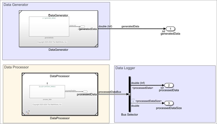
In this example, four model components generate and process unbounded-size data. The Data Generator generates the unbounded size data, the Event Scheduler passes the data to the Data Processor, and the processed data is logged using the Data Logger.
This model uses the following features and blocks that support unbounded variable-size signals.
- Simulink Function block
- MATLAB Function block
- Stateflow® Chart that uses MATLAB® as action language
- Variant Subsystem block
- For Iterator Subsystem block
- Bus Creator block
- Selector block
- Assignment block
- Bus Selector block
- Probe block
- Outport block
- Simulink. Bus object
The Data Processor component uses an export-function model, DataProcessor, that contains a Simulink® function to process the generated data. You can integrate the code generated from this model with an external user-written code. For information about C++ code generation for the data processor, see Generate C++ Code for Export-Function Models That Process Unbounded Variable-Size Data (Embedded Coder).
Open the model.
mdl = "UVSCompMdl.slx"; open_system(mdl)

Data Generator
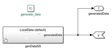
At each time step of model simulation, the Data Generator component outputs a one-dimensional array that is carried by an unbounded variable-size signal. This array is generated using a MATLAB function, createArray and its size changes based on the function input.
This createArray function is placed in a variant subsystem that executes based on the active value of the variant expression useSFcnToMimicHandCodeIntegration that is defined in the base workspace. This variant subsystem is inside a Simulink function, generate_data, that defines the data generator.
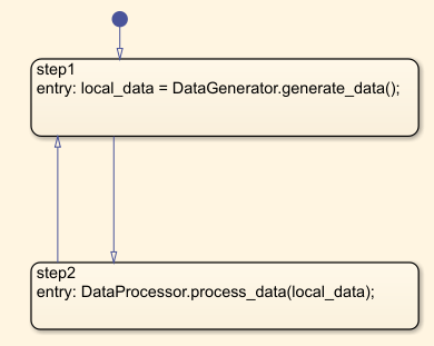
Event Scheduler
The event scheduler component schedules data transfer between the data generator and the data processor. The scheduler contains a Stateflow Chart that calls the generate_data and process_data functions to pass the generated data to the processor.
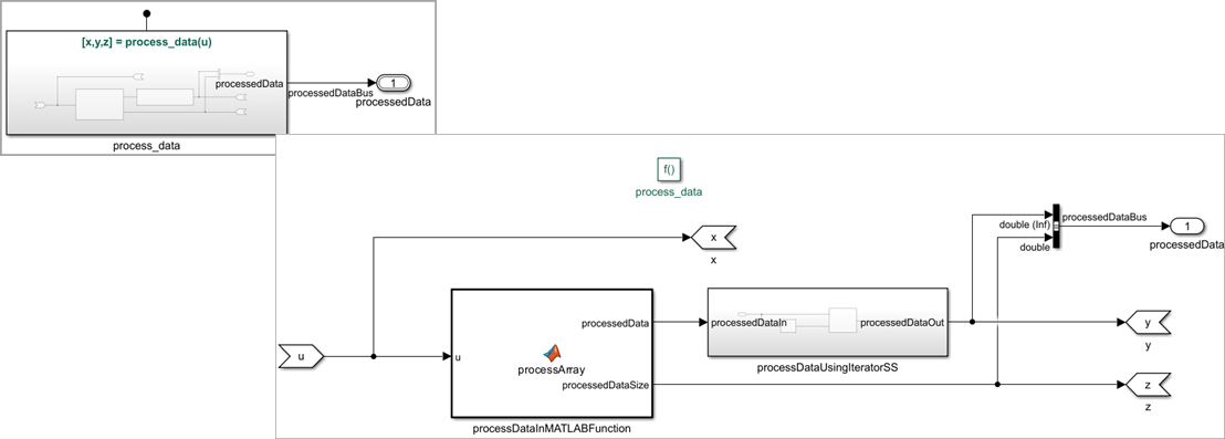
Data Processor
The Data Processor component processes the data from the Data Generator.
- The Simulink function contains a MATLAB function,
processArray, that amplifies the input array values by a factor of two and calculates the array length. - Output of the MATLAB function is passed through a subsystem. This subsystem contains a For Iterator Subsystem block that is iterated for the same number of times as the length of the input array.
- Inside the for-iterator subsystem, all input data is selected and amplified by a factor
10. The amplified value is reassigned to the input array, and the initial values are replaced with these values. The subsystem outputs an unbounded variable-size signal,processedDataout, that carries the final array values. - A Bus Creator block creates a non-virtual bus,
processedDataBus, that includes the unbounded variable-size signalprocessedDataoutand the array sizeprocessedDataSize.
Data Logger
The Data Logger uses Outport blocks to log the processed data, and the data size at each time step of model simulation. To extract the processed output data and the array size, the output bus from the data processor is passed through a Bus Selector block.
Model Configuration
This model uses a Simulink. ConfigSet object configSet that contains the configuration settings for both model simulation and code generation. This object is loaded from dHarness.mat. To view the settings, from the base workspace, click on configSet.
- In the Solver pane, in the Solver Section, Type is set to
Fixed-Stepand Solver is set todiscrete. The Fixed-step size is set to the default setting,auto. - In the Data Import/Export pane, Format is set to the default setting,
Dataset. - In the Simulation Target pane, Language is set to
C++, and Dynamic memory allocation in MATLAB functions is selected. - In the Code Generation pane, System target file is set to
ert.tlcand Language toC++. - In the Interface pane, select Support: variable-size signals and set Array layout to
Column-major.
Model Simulation and Data Logging
Simulate the model. The sim function also outputs a Simulink.SimulinkSimulation object that contains the logged data information.
Access Logged Data
Use the get function to access the logged signals from the logged data.
simout = find(out,"yout");
Use dot notation to extract the values of each signal. These values can be accessed from the base workspace.
generatedDataOut = simout{1}.Values; processedDataOut = simout{2}.Values; processedDataSizeOut = simout{3}.Values;
See Also
Chart (Stateflow) | Subsystem | Variant Subsystem | MATLAB Function | Simulink Function | Bus Selector