Load Input Data for Bus Using In Bus Element Blocks - MATLAB & Simulink (original) (raw)
This example shows how to use In Bus Element blocks to load external input data for bus elements. Using In Bus Element blocks allows flexibility in the design and implementation of external interfaces for buses.
- In Bus Element blocks can load data for an element of a bus or an entire bus.
- You do not need to specify the data type for an In Bus Element block using a
Simulink.Busobject unless the block loads data for an entire bus. - Multiple In Bus Element blocks can select the same bus element.
- You can load only the elements of the bus that you need in the model. You do not need to add blocks to select unused elements.
- The external input data you specify can contain data for every element of the bus or only some elements of the bus.
Open and Inspect Model
Open the model LoadInBusElement. The model has one port named InBus that is defined using three In Bus Element blocks. Each In Bus Element block connects to a Display block. The Dashboard Scope block below each In Bus Element and Display block pair plots the signal that the In Bus Element block creates from the loaded data.
mdl = "LoadInBusElement"; open_system(mdl)
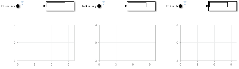
The label of each In Bus Element block indicates the name of the port and the bus element the block selects. From left to right, the In Bus Element blocks in the model have these labels:
InBus.a.x— The block selects the leaf element namedxfrom the bus namedanested inside the bus associated with the port namedInBus.InBus.a.y— The block selects the leaf element namedyfrom the bus namedanested inside the bus associated with the port namedInBus.InBus.b— The block selects the leaf element namedbin the bus associated with the port namedInBus.
The Input parameter for the model specifies the external input data for top-level input ports to load during simulation. To check the current value of the Input parameter for the model LoadInBusElement:
- Open the Configuration Parameters dialog box. In the Simulink® Toolstrip, on the Modeling tab, click Model Settings.
- On the Data Import/Export pane, check that the Input parameter is selected and configured to load data from the variable named
inbusdata.
The variable inbusdata maps to the port named InBus according to the Port Number defined in the In Bus Element dialog box.
Alternatively, programmatically check the model configuration by using the get_param function to check the values of the LoadExternalInput and ExternalInputData parameters.
get_param(mdl,"LoadExternalInput")
get_param(mdl,"ExternalInput")
Create External Input Data for Bus
Specify external input data for a bus as a structure with hierarchy and field names that match the hierarchy and element names of the bus. Specify the data for each leaf element as a timeseries object, a timetable that contains data in only one column, or a matlab.io.datastore.SimulationDatastore object. This example creates the structure using a timetable for each bus element.
Create a column vector of time values that start at 0 and end at 10 with a step size of 1.
Use the time vector to create data that represents a sine wave, a constant, and a line.
sinedata = sin(t); constdata = 3*ones(11,1); linedata = linspace(0,10,11)';
To create a timetable, the input values you provide must be a duration vector. Use the seconds function to convert the time vector to a duration vector with units of seconds.
Create a timetable object to contain the data for each type of signal.
sine = timetable(t,sinedata); const = timetable(t,constdata); line = timetable(t,linedata);
Construct the structure inbusdata that provides the input data for the port in the model. The structure field names must match the bus element names.
inbusdata.a.x = const; inbusdata.a.y = line; inbusdata.b = sine;
Fully Specify Input Data
The data in the structure inbusdata fully specifies data for the signal selected by the In Bus Element blocks in the model. The structure contains data for:
- All known elements of the bus
- All elements selected by In Bus Element blocks in the model
Simulate the model and observe the signals on the Dashboard Scope blocks. In the Simulink Toolstrip, on the Simulation tab, click Run.
Alternatively, run the simulation using the sim function.

The plots in the Dashboard Scope blocks show that each In Bus Element block produces a signal in the model that matches the data specified in the structure inbusdata.
- The leftmost In Bus Element block selects the element named
xand produces a constant signal with a value of 3. - The middle In Bus Element block selects the element named
yand produces a signal with values that create a line. - The rightmost In Bus Element block selects the element named
band produces a sine wave signal.
Partially Specify Input Data
When you use In Bus Element blocks to select bus elements, you can partially specify external input data for the bus. A structure partially specifies input data for a bus if the structure does not contain a signal for:
- Every element in the bus
- Every element selected by an In Bus Element block in the model
The In Bus Element block produces ground values throughout the simulation selected elements that do not have data in the structure.
For example, edit the label for the In Bus Element block that selects element a.y so that the block selects element a.z. Alternatively, use the set_param function to specify the element to select.
blkpth = mdl + "/Bus Element In1"; set_param(blkpth,Element="a.z")
Simulate the model without modifying the structure. The structure that maps to the port named InBus partially specifies data for the model because the structure does not contain data for an element named z inside the nested bus named a.
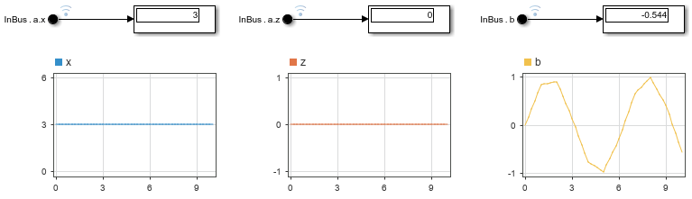
The plots of the Dashboard Scope blocks show that:
- The leftmost In Bus Element block selects the element named
xand produces a constant signal with a value of 3. - The middle In Bus Element block selects the element named
zand produces ground values, in this case a constant signal with a value of 0. - The rightmost In Bus Element block selects the element named
band produces a sine wave signal.
Revert the change to the In Bus Element block that selects element a.z so that the block selects element a.y.
set_param(blkpth,Element="a.y")
Overspecify Input Data
When you use In Bus Element blocks to select bus elements, you can overspecify external input data for the bus. A structure overspecifies input data for a bus if the structure contains data for bus elements that no In Bus Element blocks associated with the top-level input port select.
For example, edit the label for the In Bus Element block that selects the element a.y so the block selects the element b. Alternatively, use the set_param function to specify the element to select.
set_param(blkpth,Element="b")
Simulate the model without modifying the structure. The structure that maps to the port named InBus overspecifies the input data for the port because none of the In Bus Element blocks selects element a.y. The simulation runs without issuing any diagnostics.
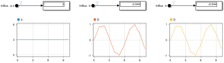
The plots of the Dashboard Scope blocks show that:
- The leftmost In Bus Element block selects the leaf element named
xand produces a constant signal with a value of 3. - The middle and rightmost In Bus Element blocks both select element
band each produce a sine wave signal.