Load Bus Data to Root-Level Input Ports - MATLAB & Simulink (original) (raw)
You can import bus data to top-level input ports by manually specifying the data in the configuration parameter or by using the Root Inport Mapper tool. For information about importing bus data using the Root Inport Mapper tool, see Import Bus Data.
Imported Bus Data Requirements
You can import virtual bus, nonvirtual bus, or array of buses data to a top-level input port defined by a Simulink.Bus object. In the top-levelInport block, set Data type toBus and specify the name of a bus object. To specify data values for buses, use a structure of:
- MATLAB®
timeseriesobjects - MATLAB
timetableobjects - A combination of
timeseriesandtimetableobjects
Bus elements for which you do not include a field in the structure use ground values. You can use an empty matrix to specify to use ground values.
Note
When you specify timetable data to load, thetimetable must contain data for only one signal.
The structure of timeseries or timetable (or both) objects must match the bus elements in terms of:
- Hierarchy
- Name of the structure field, which must match the bus element name. (The
nameproperty of thetimeseriesobject does not need to match the bus element name.) - Data type
- Dimensions
- Complexity
The order of the structure fields does not have to match the order of the bus elements.
You can include the structure as an element of a Dataset object. You can use a structure in a comma-separated list. You can specify an empty matrix in a comma-separated list. The empty matrix uses the ground values for the bus signal.
For example, to load data for input ports in1 andin3, and to use ground values for port in2, enter the following in the Input parameter:
Initialize Bus Signals
You can initialize bus signals, including using partial specification of initialization data. For details, see Specify Initial Conditions for Bus Elements.
For details about importing array of bus data to a root Inport block, see Import Array of Buses Data.
Limitations for Importing Bus Data to Top-Level Inputs
The signal data that you can use the Root Inport Mapper tool to import and map to a top-level Inport block can include bus data. You cannot use that tool to map bus signals to a top-level Enable or Trigger block.
You cannot use input ports to import buses in external modes. To import bus data in rapid accelerator mode, use Dataset format.
Open Example Materials
This example uses these files:
InportLoadingBus: Model that contains a top-level Inport block configured to load input data for a busLoadPartialAOB: Model that loads partial input data for an array of busespartialAOBData.m: Function that createsSimulink.Busobjects and data for the modelLoadPartialAOBto loadBasicColors.m: Enumeration class definition to define data type used bySimulink.Busobjects in this example
To access these files, open the example. Then, run the code that opens the file you need.
Open the model InportLoadingBus.
open_system("InportLoadingBus")
Open the model LoadPartialAOB.
open_system("LoadPartialAOB")
Open the MATLAB® file partialAOBData.m.
Open the enumeration class definition file BasicColors.m.
Import Bus Data to a Top-Level Inport
This model has two Inport blocks connected to Scope blocks. The data type of the In1 block is inherited (nonbus data) and the data type of the In2 block is defined by the bus objectBusObject. The model has a callback that loadsBusObject and its sub-bus BusObject1.
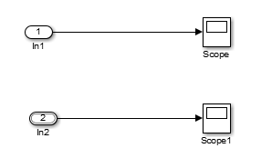
The BusObject bus object has two elements:
cs1, which is a nested bus that has two elements:ab
- Open the model
InportLoadingBus. - Create a
timeseriesobject that contains data for the first input port to load. This input port loads nonbus data.
t1 = (1:10)';
d1 = sin(t1);
in1 = timeseries(d1,t1); - Create an input structure, which can consist of
timeseriesobjects ortimetableobjects, or a combination of those types of objects. Create onetimeseriesortimetableobject for each leaf bus element for which you do not want to use ground values. This example uses ground values for thebbus element, so it does not need atimeseriesortimetableobject for that element.
t2 = (1:5)';
d2 = cos(t2);
in2.c = timeseries(d1,t1);
in2.s1.a = timetable(seconds(t2),d2);
Thetimeseriesobjects that you create must match the corresponding bus elements, as described in Imported Bus Data Requirements. - Create a
Datasetobject and addin1andin2the object.
ds = Simulink.SimulationData.Dataset;
ds = ds.addElement(in1,'in1_signal');
ds = ds.addElement(in2,'in2_signal'); - Open the Configuration Parameters dialog box. On the Modeling tab, click Model Settings.
- On the Data Import/Export pane, selectInput.
- In the Input field, enter the name of the
Datasetobjectds.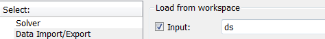
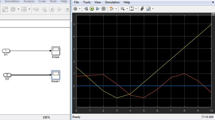
- Simulate the model. The Scope block connected to the second input port shows the imported bus data.
Get Information About Bus Objects
To determine the number of timeseries objects and data type, complexity, and dimensions needed for creating a structure of timeseries objects from a bus, use these functions:
For example, for the bus object BusObject:
numElem = getNumLeafBusElements(BusObject)
elemList = getLeafBusElements(BusObject)
elemList =
3x1 BusElement array with properties:
Min
Max
DimensionsMode
SampleTime
Description
Units
Name
DataType
Complexity
Dimensions
Create Structures of Timeseries Objects from Buses
If you have timeseries objects defined, you can use them to create a structure of timeseries objects based on a bus object. Use the Simulink.SimulationData.createStructOfTimeseries function. For example, if you have defined timeseries objects ts1,ts2, and ts3, and you have a bus objectMyBusObject, you can use this command to create a structure oftimeseries objects.
input = Simulink.SimulationData.createStructOfTimeseries(... 'MyBusObject',{ts1,ts2,ts3});
The number of timeseries objects in the cell array must match the number of leaf elements in the bus object. The data type, dimensions, and complexity of eachtimeseries object must match those attributes of the corresponding bus object leaf node.
Import Array of Buses Data
To load data for an array of buses using a top-level Inport block, use an array of structures of timeseries objects.
Note
You cannot use an Enable, Trigger, or From File block to import data for an array of buses.
Full Specification of Data
You can use logged data for an array of buses from a previous simulation as round trip input to a top-level Inport block in a subsequent simulation. The logged data is a full specification of data for the array of buses.
If you construct an array of structures of timeseries objects to specify the data to import:
- Specify the structure fields in the same order as the signals in the bus.
- Do not include more fields in the structure than there are signals in the bus.
For leaf fields, match exactly the data type, dimensions, and complexity of the corresponding signal in the bus.
Partial Specification of Data
To specify partial data for array of buses, create an array of structures withtimeseries objects at the leaf nodes.
The structure that you create to specify partial data must be consistent with these rules:
- You can omit fields, including leaf nodes and subbranches. You can also omit dimensions. If you do not specify a field, the software uses the ground value for that field.
- For nested bus nodes, make the dimension of each field equal to, or smaller than, the dimension for the corresponding node of the array of buses.
This example shows how you can specify partial data to be imported using a top-levelInport block whose data type is defined as theSimulink.Bus object MyBus. You can open the modelLoadPartialAOB and the MATLAB code that defines the data to importpartialAOBData.m.
When you simulate the model, you see that several of the Display blocks connected to elements of the array of buses display DefaultColor, the ground value for the bus. Other Display blocks connected to other array of buses elements display the value defined in the partial array of buses data.
The Inport block uses the MyBus bus object as its data type.
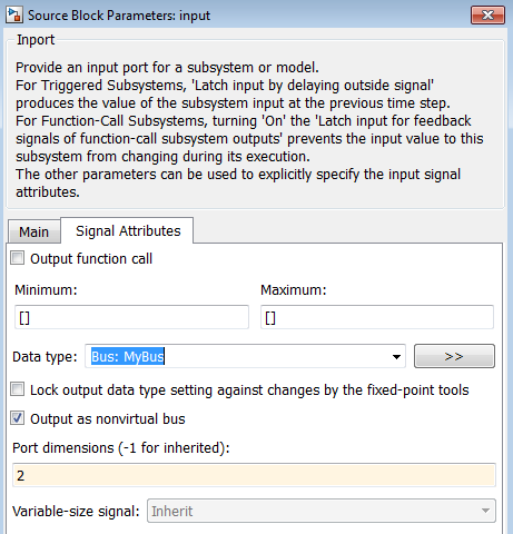
The MyBus array of buses includes MyBus(1) andMyBus(2). The port dimension is set to 2 to reflect the two buses in the array of buses, and Output as nonvirtual bus is enabled.
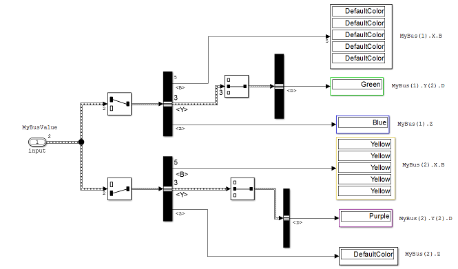
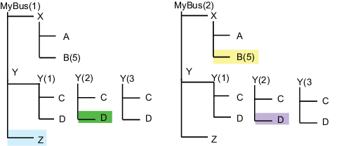
Here are the elements of the array of buses, which includesMyBus(1) and MyBus(2). The color highlighting shows the nodes of the array of buses for which data is being imported.
Here is MATLAB code that defines the data to import. The color that highlights the code matches the color of the corresponding node in the array of buses. To view the code used in this model, open the MATLAB code file partialAOBData.m.
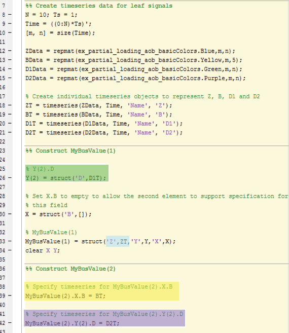
In the code that defines the import data:
- The
timeseriesobjectMyBusValuespecifies the data for the highlighted nodes. - The
timeseriesobjectBTforMyBus(2), becauseBTis a leaf node, it must match exactly the dimensions, data type, and complexity of the corresponding bus element. - The structure specifies data for
Y(2). You can skip the first and last nested buses ofY(that is,Y(1)andY(3)).
This example specifies data for Y(2); you can skip the first and last nested buses of Y (that is, Y(1) andY(3)).
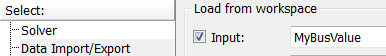
After you define the MyBusValue variable for the import data, set the > > parameter to MyBusValue.
See Also
Topics
- Load Input Data for Bus Using In Bus Element Blocks
- Import Bus Data
- Imported Bus Data Requirements
- Load Data to Root-Level Input Ports
- Specify Initial Conditions for Bus Elements
- Import Array of Buses Data
- Map Root Inport Signal Data
- Composite Interface Guidelines
- Specify Bus Properties with Bus Objects