dsp.FIRHalfbandInterpolator - Interpolate signal using polyphase FIR halfband filter - MATLAB (original) (raw)
Interpolate signal using polyphase FIR halfband filter
Description
The dsp.FIRHalfbandInterpolator System object™ performs efficient polyphase interpolation of the input signal using an upsampling factor of two. You can use dsp.FIRHalfbandInterpolator to implement the synthesis portion of a two-band filter bank to synthesize a signal from lowpass and highpass subbands. dsp.FIRHalfbandInterpolator uses an FIR equiripple design or a Kaiser window design to construct the halfband filters and a polyphase implementation to filter the input. For more details, see Algorithms.
To upsample and interpolate your data:
- Create the
dsp.FIRHalfbandInterpolatorobject and set its properties. - Call the object with arguments, as if it were a function.
To learn more about how System objects work, see What Are System Objects?
This object supports C/C++ code generation and SIMD code generation under certain conditions. This object also supports code generation for ARM® Cortex®-M and ARM Cortex-A processors. For more information, seeCode Generation.
Creation
Syntax
Description
`firhalfbandinterp` = dsp.FIRHalfbandInterpolator returns a FIR halfband interpolation filter,firhalfbandinterp, with the default settings. Under the default settings, the System object upsamples and interpolates the input data using a halfband frequency of 11025 Hz, a transition width of4.1 kHz, and a stopband attenuation of80 dB. The design method is set to"Auto".
`firhalfbandinterp` = dsp.FIRHalfbandInterpolator(`Name=Value`) sets properties using one or more name-value arguments.
Example: firhalfbandinterp = dsp.FIRHalfbandInterpolator(Specification="Filter order and stopband attenuation") creates an FIR halfband interpolator object with filter order set to 52 and stopband attenuation set to 80 dB.
.
Properties
Unless otherwise indicated, properties are nontunable, which means you cannot change their values after calling the object. Objects lock when you call them, and therelease function unlocks them.
If a property is tunable, you can change its value at any time.
For more information on changing property values, seeSystem Design in MATLAB Using System Objects.
Filter design parameters, specified as a character vector. When you setSpecification to one of the following, you choose two of the three available design parameters to design the FIR Halfband filter.
"Transition width and stopband attenuation"–– Transition width and stopband attenuation are the design parameters."Filter order and stopband attenuation"–– Filter order and stopband attenuation are the design parameters."Filter order and transition width"–– Filter order and transition width are the design parameters.
The filter is designed using optimal equiripple filter design method.
When you set Specification to"Coefficients", you specify the halfband filter coefficients directly through the Numerator property.
Filter order, specified as an even positive integer.
Dependencies
To enable this property, set Specification to"Filter order and stopband attenuation" or"Filter order and transition width".
Data Types: single | double | int8 | int16 | int32 | int64 | uint8 | uint16 | uint32 | uint64
Stopband attenuation in dB, specified as a positive real scalar.
Dependencies
To enable this property, set Specification to"Filter order and stopband attenuation" or"Transition width and stopband attenuation".
Data Types: single | double | int8 | int16 | int32 | int64 | uint8 | uint16 | uint32 | uint64
Transition width in Hz, specified as a positive real scalar or in normalized frequency units (since R2023b).
If you set theNormalizedFrequency property to:
false–– The value of the transition width is in Hz and must be less than half the output sample rate (2 ×SampleRateproperty) value.true–– The value of the transition width is in normalized frequency units. The value must be a positive scalar less than1.0.
When you set theNormalizedFrequencyproperty totruewhile creating the object and you do not set the transition width, the default transition width is automatically set to normalized frequency units using the default sample rate at which the filter operates (2 × 44100) Hz. The filter in the halfband interpolator effectively runs at twice the sample rate of the input signal.
When you set theNormalizedFrequencyproperty totrueafter you create the object, the transition width must be specified in normalized units before you run the object algorithm. To specify the normalized frequency value, setNormalizedFrequencytotrueand manually convert the frequency value in Hz to the normalized value using the input sample rate in Hz. For example, if the input sample rate_Fs_ is 44100 Hz, the corresponding transition width value in normalized units is_TWHz_/(2×Fs/2).
firhalfbandinterp = dsp.FIRHalfbandInterpolator;
firhalfbandinterp.NormalizedFrequency = true;
firhalfbandinterp.TransitionWidth = 4100/((2x44100)/2)
(since R2023b)
Dependencies
To enable this property, set Specification to"Transition width and stopband attenuation" or"Filter order and transition width".
Data Types: single | double | int8 | int16 | int32 | int64 | uint8 | uint16 | uint32 | uint64
FIR halfband filter coefficients, specified as a row vector. The coefficients must comply with the FIR halfband impulse response format. For details on this format, see Halfband Filters and FIR Halfband Filter Design. If half the order of the filter, (length(Numerator) - 1)/2 is even, every other coefficient starting from the first coefficient must be a zero except for the center coefficient which must be a 1.0. If half the order of the filter is odd, the sequence of alternating zeros with a 1.0 at the center starts at the second coefficient.
Dependencies
To enable this property, set Specification to"Coefficients".
Data Types: single | double | int8 | int16 | int32 | int64 | uint8 | uint16 | uint32 | uint64
Specify the filter design method as one of the following:
"Auto"–– The algorithm automatically chooses the filter design method depending on the filter design parameters. The algorithm uses the equiripple or the Kaiser window method to design the filter.
If the design constraints are very tight, such as very high stopband attenuation or very narrow transition width, then the algorithm automatically chooses the Kaiser method, as this method is optimal for designing filters with very tight specifications. However, if the design constraints are not tight, then the algorithm chooses the equiripple method.
When you set theDesignMethodproperty to"Auto", you can determine the method used by the algorithm by examining the passband and stopband ripple characteristics of the designed filter. If the object used the equiripple method, the passband and stopband ripples of the designed filter have a constant amplitude in the frequency response. If the filter design method the object chooses in the"Auto"mode is not suitable for your application, manually specify theDesignMethodas"Equiripple"or"Kaiser"."Equiripple"–– The algorithm uses the equiripple method."Kaiser"–– The algorithm uses the Kaiser window method.
For more details on these two methods, see Algorithms.
Dependencies
To enable this property, set Specification to"Transition width and stopband attenuation","Filter order and stopband attenuation", or"Filter order and transition width".
Data Types: char | string
Synthesis filter bank, specified as either false ortrue. If this property is false,dsp.FIRHalfbandInterpolator is an interpolation filter for a single vector- or matrix-valued input when you call the algorithm. If this property is true, dsp.FIRHalfbandInterpolator is a synthesis filter bank and the algorithm accepts two inputs, the lowpass and highpass subbands to synthesize.
Since R2023b
Flag to set frequencies in normalized units, specified as one of these values:
true–– The transition width must be in the normalized frequency units and less than1.0.
When you set theNormalizedFrequencyproperty totruewhile creating the object and you do not set the transition width, the default transition width is automatically set to normalized frequency units using the default sample rate at which the filter operates (2 × 44100) Hz. The filter in the halfband interpolator effectively runs at twice the sample rate of the input signal.
When you set theNormalizedFrequencyproperty totrueafter you create the object, the transition width must be specified in normalized units before you run the object algorithm. To specify the normalized frequency value, setNormalizedFrequencytotrueand manually convert the frequency value in Hz to the normalized value using the input sample rate in Hz. For example, if the input sample rate_Fs_ is 44100 Hz, the corresponding transition width value in normalized units is_TWHz_/(2×Fs/2).
firhalfbandinterp = dsp.FIRHalfbandInterpolator;
firhalfbandinterp.NormalizedFrequency = true;
firhalfbandinterp.TransitionWidth = 4100/((2x44100)/2)false–– The transition width is in Hz. You can specify the input sample rate through theSampleRateproperty.
Dependency
To enable this property, set Specification to any accepted value except "Coefficients".
Data Types: logical
Input sample rate in Hz, specified as a positive real scalar. The input sample rate defaults to 44100 Hz. If you specify a transition width as one of your filter design parameters, the transition width cannot exceed 1/2 the output sample rate (2 × SampleRate property) value.
Dependency
To enable this property, set:
Specificationto any accepted value except"Coefficients".NormalizedFrequencytofalse. (since R2023b)
Data Types: single | double
Fixed-Point Properties
Word and fraction lengths of coefficients, specified as a signed or unsigned numerictype object. The default,numerictype(1,16) corresponds to a signed numeric type object with 16-bit coefficients and a fraction length determined based on the coefficient values, to give the best possible precision.
This property is not tunable.
Word length of the output is same as the word length of the input. Fraction length of the output is computed such that the entire dynamic range of the output can be represented without overflow. For details on how the fraction length of the output is computed, see Fixed-Point Precision Rules for Avoiding Overflow in FIR Filters.
Rounding method for output fixed-point operations, specified as a character vector. For more information on the rounding modes, see Precision and Range.
Usage
Syntax
Description
[y](#d126e294012) = firhalfbandinterp([x1](#d126e293904)) upsamples by two and interpolates the input signal x1 using the FIR halfband interpolator, firhalfbandinterp.
[y](#d126e294012) = firhalfbandinterp([x1](#d126e293904),[x2](#d126e293955)) implements a halfband synthesis filter bank for the inputsx1 and x2. x1 is the lowpass output of a halfband analysis filter bank andx2 is the highpass output of a halfband analysis filter bank. dsp.FIRHalfbandInterpolator implements a synthesis filter bank only when the FilterBankInputPort property is set totrue.
Input Arguments
Data input to the FIR halfband interpolator, specified as a column vector or a matrix. This signal is the lowpass output of a halfband analysis filter bank. If the input signal is a matrix, each column of the matrix is treated as an independent channel.
Data Types: single | double | int8 | int16 | int32 | int64 | uint8 | uint16 | uint32 | uint64 | fi
Complex Number Support: Yes
Second data input to the synthesis filter bank, specified as a column vector or a matrix. This signal is the highpass output of a halfband analysis filter bank. If the input signal is a matrix, each column of the matrix is treated as an independent channel.
The size, data type, and complexity of both the inputs must be the same.
Data Types: single | double | int8 | int16 | int32 | int64 | uint8 | uint16 | uint32 | uint64 | fi
Complex Number Support: Yes
Output Arguments
Output of the interpolator, returned as a column vector or a matrix. The number of rows in the interpolator output is twice the number of rows in the input signal.
Data Types: single | double | int8 | int16 | int32 | int64 | uint8 | uint16 | uint32 | uint64 | fi
Complex Number Support: Yes
Object Functions
To use an object function, specify the System object as the first input argument. For example, to release system resources of a System object named obj, use this syntax:
| freqz | Frequency response of discrete-time filter System object |
|---|---|
| freqzmr | Compute DTFT approximation of impulse response of multirate or single-rate filter |
| filterAnalyzer | Analyze filters with Filter Analyzer app |
| info | Information about filter System object |
| cost | Estimate cost of implementing filter System object |
| coeffs | Returns the filter System object coefficients in a structure |
| polyphase | Polyphase decomposition of multirate filter |
| outputDelay | Determine output delay of single-rate or multirate filter |
| step | Run System object algorithm |
|---|---|
| release | Release resources and allow changes to System object property values and input characteristics |
| reset | Reset internal states of System object |
Examples
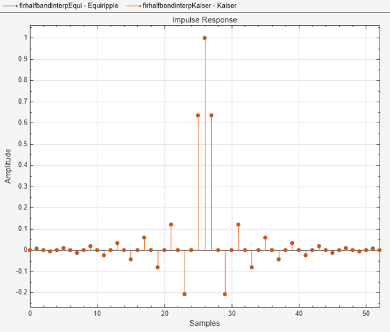
Create two lowpass halfband interpolation filters. The design method in the first filter is set to "Equiripple" and in the second filter is set to "Kaiser".
Specify a filter order of 52 and a transition width of 0.0930 in normalized frequency units.
Order = 52; TW = 0.0930; filterspec = "Filter order and transition width";
firhalfbandinterpEqui = dsp.FIRHalfbandInterpolator(... NormalizedFrequency=true,... Specification=filterspec,... FilterOrder=Order,... TransitionWidth=0.0930,... DesignMethod="Equiripple");
firhalfbandinterpKaiser = dsp.FIRHalfbandInterpolator(... NormalizedFrequency=true,... Specification=filterspec,... FilterOrder=Order,... TransitionWidth=TW,... DesignMethod="Kaiser");
Plot the impulse response of both the filters. The zeroth-order coefficient is delayed by 26 samples, which is equal to the group delay of the filter. This yields a causal halfband filter.
hfvt = filterAnalyzer(firhalfbandinterpEqui,firhalfbandinterpKaiser,... Analysis="impulse"); setLegendStrings(hfvt,["Equiripple","Kaiser"])
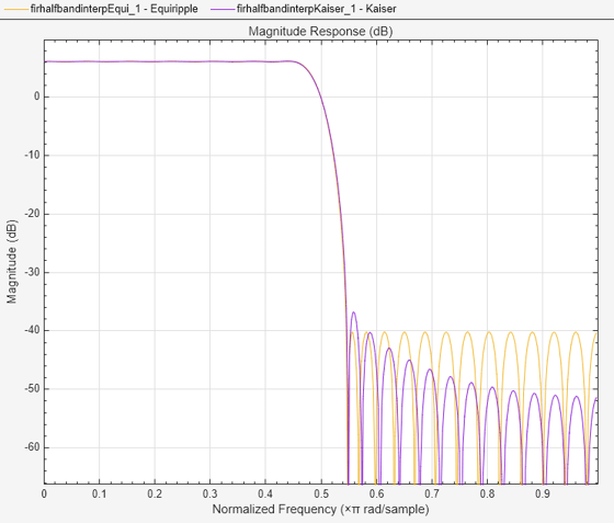
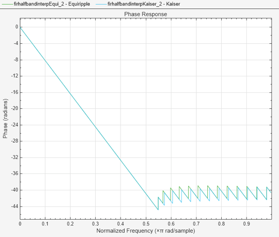
Plot the magnitude and phase response.
If the filter specifications are tight, say a very high filter order with a very narrow transition width, the filter designed using the "Kaiser" method converges more effectively.
hvftMag = filterAnalyzer(firhalfbandinterpEqui,firhalfbandinterpKaiser,... Analysis="magnitude"); setLegendStrings(hvftMag,["Equiripple","Kaiser"])
hvftPhase = filterAnalyzer(firhalfbandinterpEqui,firhalfbandinterpKaiser,... Analysis="phase"); setLegendStrings(hvftPhase,["Equiripple","Kaiser"])
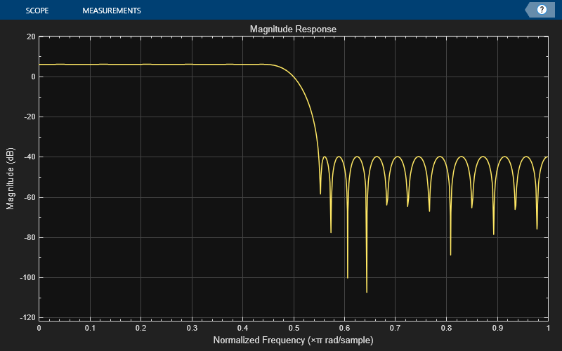
Design an equiripple FIR halfband interpolator object of order 48 using the designHalfbandFIR function. Set the Verbose argument to true.
hbFIR = designHalfbandFIR(FilterOrder=48,SystemObject=true,... Structure="interp",Verbose=true)
designHalfbandFIR(FilterOrder=48, TransitionWidth=0.1, DesignMethod="equiripple", Passband="lowpass", Structure="interp", InputSampleRate="normalized", PhaseConstraint="linear", Datatype="double", SystemObject=true)
hbFIR = dsp.FIRHalfbandInterpolator with properties:
      Specification: 'Coefficients'
          Numerator: [0 -0.0082 0 0.0079 0 -0.0116 0 0.0165 0 -0.0227 0 0.0309 0 -0.0419 0 0.0571 0 -0.0800 0 0.1193 0 -0.2073 0 0.6350 1 0.6350 0 -0.2073 0 0.1193 0 -0.0800 0 0.0571 0 -0.0419 0 0.0309 0 -0.0227 0 0.0165 0 -0.0116 0 … ] (1×49 double)
FilterBankInputPort: false
Show all properties
Create a dsp.DynamicFilterVisualizer object and visualize the magnitude response of the filter.
dfv = dsp.DynamicFilterVisualizer(NormalizedFrequency=true); dfv(hbFIR);
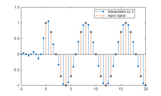
The input is a cosine wave with an angular frequency of π4 radians/sample.
input = cos(pi/4*(0:39)');
Interpolate the cosine signal using the FIR halfband interpolator.
Plot the original and interpolated signals. In order to plot the two signals on the same plot, you must account for the output delay introduced by the FIR halfband interpolator and the scaling introduced by the filter. Use the outputDelay function to compute the delay value introduced by the interpolator. Shift the output by this delay value.
Visualize the input and the resampled signals. The input and output values coincide every other sample due to the interpolation factor of 2.
[delay,FsOut] = outputDelay(hbFIR,FsIn=1)
nInput = (0:length(input)-1); tOutput = (0:length(output)-1)/FsOut-delay; stem(tOutput,output,"filled",MarkerSize=4); hold on; stem(nInput,input); hold off; xlim([-5,20]) legend("Interpolated by 2","Input signal",Location="best");
Use a halfband analysis filter bank and interpolation filter to extract the low frequency subband from a speech signal.
Note: The audioDeviceWriter System object™ is not supported in MATLAB Online.
Set up the audio file reader, the analysis filter bank, audio device writer, and interpolation filter. The sample rate of the audio data is 22050 Hz. The order of the halfband filter is 52, with a transition width of 2 kHz.
Set the design method to "Auto". This mode chooses one of the filter design methods, equiripple or Kaiser, based on the design parameters of the filter.
afr = dsp.AudioFileReader(... "speech_dft.mp3",... SamplesPerFrame=1024);
filtSpec = "Filter order and transition width"; Order = 52; TW = 2000;
firhalfbanddecim = dsp.FIRHalfbandDecimator(... Specification=filtSpec,... FilterOrder=Order,... TransitionWidth=TW,... DesignMethod="Auto",... SampleRate=afr.SampleRate);
firhalfbandinterp = dsp.FIRHalfbandInterpolator(... Specification=filtSpec,... FilterOrder=Order,... TransitionWidth=TW,... DesignMethod="Auto",... SampleRate=afr.SampleRate/2);
adw = audioDeviceWriter(SampleRate=afr.SampleRate);
View the magnitude response of the halfband filter.
filterAnalyzer(firhalfbanddecim)
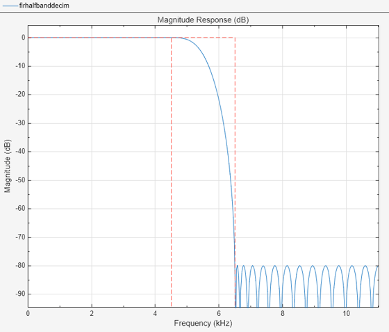
Read the speech signal from the audio file in frames of 1024 samples. Filter the speech signal into lowpass and highpass subbands with a halfband frequency of 5512.5 Hz. Reconstruct a lowpass approximation of the speech signal by interpolating the lowpass subband. Play the filtered output.
while ~isDone(afr) audioframe = afr(); xlo = firhalfbanddecim(audioframe); ylow = firhalfbandinterp(xlo); adw(ylow); end
Wait until the audio file is played to the end, then close the input file and release the audio output resource.
release(afr);
release(adw);
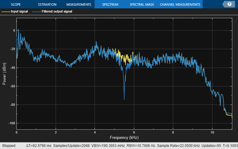
Use a halfband decimator and interpolator to implement a two-channel filter bank. This example uses an audio file input and shows that the power spectrum of the filter bank output does not differ significantly from the input.
Note: The audioDeviceWriter System object™ is not supported in MATLAB Online.
Set up the audio file reader and device writer. Construct the FIR halfband decimator and interpolator. Finally, set up the spectrum analyzer to display the power spectra of the filter-bank input and output.
AF = dsp.AudioFileReader("speech_dft.mp3",SamplesPerFrame=1024); AP = audioDeviceWriter(SampleRate=AF.SampleRate);
filterspec = "Filter order and transition width"; Order = 52; TW = 2000;
firhalfbanddecim = dsp.FIRHalfbandDecimator(... Specification=filterspec,FilterOrder=Order,... TransitionWidth=TW,DesignMethod="Auto",... SampleRate=AF.SampleRate);
firhalfbandinterp = dsp.FIRHalfbandInterpolator(... Specification=filterspec,FilterOrder=Order,... TransitionWidth=TW,SampleRate=AF.SampleRate/2,... DesignMethod="Auto",... FilterBankInputPort=true);
SpecAna = spectrumAnalyzer(SampleRate=AF.SampleRate,... PlotAsTwoSidedSpectrum=false,... ShowLegend=true,... ChannelNames={"Input signal","Filtered output signal"});
Read the audio 1024 samples at a time. Filter the input to obtain the lowpass and highpass subband signals decimated by a factor of two. This is the analysis filter bank. Use the halfband interpolator as the synthesis filter bank. Display the running power spectrum of the audio input and the output of the synthesis filter bank. Play the output.
while ~isDone(AF) audioInput = AF(); [xlo,xhigh] = firhalfbanddecim(audioInput); audioOutput = firhalfbandinterp(xlo,xhigh); spectrumInput = [audioInput audioOutput]; SpecAna(spectrumInput); AP(audioOutput); end
release(AF); release(AP); release(SpecAna);
Create a half-band interpolation filter. The filter order is 52 with a transition width of 0.0930 in normalized frequency units. Use the filter to upsample and interpolate a multichannel input.
Set the design method to "Auto". This mode chooses one of the filter design methods, equiripple or Kaiser, based on the specified filter design parameters.
Fs = 44.1e3;
filterspec = "Filter order and transition width";
Order = 52;
TW = 0.0930;
firhalfbandinterp = dsp.FIRHalfbandInterpolator(...
NormalizedFrequency=true,...
Specification=filterspec,...
FilterOrder=Order,...
TransitionWidth=TW,...
DesignMethod="Auto");
x = randn(1024,4); y = firhalfbandinterp(x);
More About
An ideal lowpass halfband filter is given by
An ideal filter is not realizable because the impulse response is noncausal and not absolutely summable. However, the impulse response of an ideal lowpass filter possesses some important properties that are required in a realizable approximation. The impulse response of an ideal lowpass halfband filter is:
- Equal to 0 for all even-indexed samples
- Equal to 1/2 at n=0 as shown by L'Hôpital's rule on the continuous-valued equivalent of the discrete-time impulse response
The ideal highpass halfband filter is given by
Evaluating the preceding integral gives the following impulse response
The impulse response of an ideal highpass halfband filter is:
- Equal to 0 for all even-indexed samples
- Equal to 1/2 at n=0
The FIR halfband interpolator uses a causal FIR approximation to the ideal halfband response, which is based on minimizing the ℓ∞ norm of the error (minimax). See Algorithms for more information.
The coefficients of a Kaiser window are computed from this equation:
where _I_0 is the zeroth-order modified Bessel function of the first kind.
To obtain a Kaiser window that represents an FIR filter with stopband attenuation of_α_ dB, use this β.
The filter order n is given by:
where Δ_ω_ is the transition width.
Algorithms
The FIR halfband interpolator algorithm uses the equiripple or the Kaiser window method to design the FIR halfband filter. When the design constraints are tight, such as very high stopband attenuation or very narrow transition width, use the Kaiser window method. When the design constraints are not tight, use the equiripple method. If you are not sure of which method to use, set the design method to Auto. In this mode, the algorithm automatically chooses a design method that optimally meets the specified filter constraints.
Halfband Equiripple Design
In the equiripple method, the algorithm uses a minimax (minimize the maximum error) FIR design to design a fullband linear phase filter with the desired specifications. The algorithm upsamples a fullband filter to replace the even-indexed samples of the filter with zeros and creates a halfband filter. It then sets the filter tap corresponding to the group delay of the filter in samples to 1/2. This yields a causal linear-phase FIR filter approximation to the ideal halfband filter defined in Halfband Filters. See [1] for a description of this filter design method using the Remez exchange algorithm. Since you can design a filter using this approximation method with a constant ripple both in the passband and stopband, the filter is also known as the equiripple filter.
Kaiser Window Design
In the Kaiser window method, the algorithm first truncates the ideal halfband filter defined in Halfband Filters, then it applies a Kaiser window defined in Kaiser Window. This yields a causal linear-phase FIR filter approximation to the ideal halfband filter.
The coefficients of the designed halfband interpolation filter are scaled by the interpolation factor, two, to preserve the output power of the signal.
For more information on designing FIR halfband filters, see FIR Halfband Filter Design.
The FIR halfband interpolator uses an efficient polyphase implementation for halfband filters when you filter the input signal. You can use a polyphase implementation to move the upsampling operation after filtering. This allows you to filter at the lower sampling rate.
Splitting a filter’s impulse response h(n) into two polyphase components results in an even polyphase component with_z_-transform of
and an odd polyphase component with _z_-transform of
The _z_-transform of the filter can be written in terms of the even and odd polyphase components as
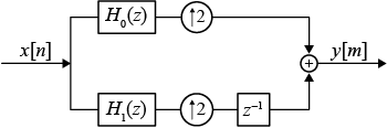
You can represent the upsampling by 2 and then filtering the signal using this figure.
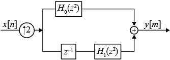
Using the multirate noble identity for upsampling, you can move the upsampling operation after the filtering. This enables you to filter at the lower rate.
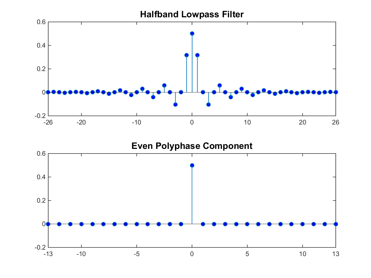
For a halfband filter, the only nonzero coefficient in the even polyphase component is the coefficient corresponding to z0. Implementing the halfband filter as a causal FIR filter shifts the nonzero coefficient to approximately z-N/4, where_N_ is the number of filter taps. This process is shown in the following figure. The top plot shows a halfband filter of order 52. The bottom plot shows the even polyphase component. Both filters are noncausal. Delaying the even polyphase component by 13 samples creates a causal FIR filter.
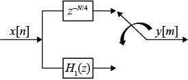
To efficiently implement the halfband interpolator, the algorithm replaces the upsampling operator, delay block, and adder with a commutator switch. The commutator switch starts on the even branch and takes input samples from the two branches alternately, one sample at a time. This doubles the sampling rate of the input signal. Which polyphase component reduces to a simple delay depends on whether the half order of the filter is even or odd.
Here is the implementation when the filter half order is even. In this diagram,_H_0(z) becomes the gain followed by the delay.
When the filter half order is odd, _H_1(z) becomes the gain followed by the delay and the switch. This is because the delay required to make the even polyphase component causal can be odd or even depending on the filter half order.
To confirm this behavior, run the following code in the MATLAB® command prompt and inspect the polyphase components of the following filters.
filterspec = "Filter order and stopband attenuation"; halfOrderEven = dsp.FIRHalfbandInterpolator(Specification=filterspec,... FilterOrder=64,StopbandAttenuation=80); halfOrderOdd = dsp.FIRHalfbandInterpolator(Specification=filterspec,... FilterOrder=54,StopbandAttenuation=80); polyphase(halfOrderEven) polyphase(halfOrderOdd)
One of the polyphase components has a single nonzero coefficient indicating that it is a simple delay. To preserve the output power of the signal, the coefficients are scaled by the interpolation factor, two. To see this scaling, compare the polyphase components of a halfband interpolator with the coefficients of a halfband decimator.
hfirinterp = dsp.FIRHalfbandInterpolator; hfirdecim = dsp.FIRHalfbandDecimator; polyphase(hfirdecim) polyphase(hfirinterp)
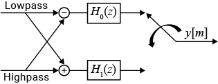
Synthesis Filter Bank
The FIR halfband interpolator implements the synthesis portion of a two-band filter bank to synthesize a signal from lowpass and highpass subbands.
For more information on filter banks, see Overview of Filter Banks.
To summarize, the FIR halfband interpolator:
- Filters the input before upsampling with the even and odd polyphase components of the filter.
- Exploits the fact that one filter polyphase component is a simple delay for a halfband filter.
- Acts as a synthesis filter bank.
References
[1] Harris, F.J. Multirate Signal Processing for Communication Systems, Prentice Hall, 2004, pp. 208–209.
Extended Capabilities
Version History
Introduced in R2014b
When you set the NormalizedFrequency property totrue, you must specify the transition width in normalized frequency units (0 to 1).
When you set the NormalizedFrequency property totrue while creating the object and you do not set the transition width, the default transition width is automatically set to normalized frequency units using the default sample rate at which the filter operates (2 × 44100) Hz. The filter in the halfband interpolator effectively runs at twice the sample rate of the input signal.
firhalfbandinterp = dsp.FIRHalfbandInterpolator(NormalizedFrequency=true)
firhalfbandinterp = dsp.FIRHalfbandInterpolator with properties:
      Specification: "Transition width and stopband attenuation"
    TransitionWidth: 0.0930
StopbandAttenuation: 80
       DesignMethod: "Auto"
FilterBankInputPort: false
NormalizedFrequency: true
Show all properties
When you set the NormalizedFrequency property to true after you create the object, the transition width must be specified in normalized units before you run the object algorithm.
firhalfbandinterp = dsp.FIRHalfbandInterpolator
firhalfbandinterp = dsp.FIRHalfbandInterpolator with properties:
      Specification: "Transition width and stopband attenuation"
    TransitionWidth: 4100
StopbandAttenuation: 80
       DesignMethod: "Auto"
FilterBankInputPort: false
NormalizedFrequency: false
         SampleRate: 44100
Show all properties
To specify the normalized frequency values, setNormalizedFrequency totrue and manually convert the frequency values in Hz to normalized values using the input sample rate in Hz. For example, if the input sample rate is 44100 Hz, the corresponding values in normalized units are computed using these equations.
firhalfbandinterp.NormalizedFrequency = true; firhalfbandinterp.TransitionWidth = 4100/((2x44100)/2)
firhalfbandinterp = dsp.FIRHalfbandInterpolator with properties:
      Specification: "Transition width and stopband attenuation"
    TransitionWidth: 0.0930
StopbandAttenuation: 80
       DesignMethod: "Auto"
FilterBankInputPort: false
NormalizedFrequency: true
Show all properties
See Also
Functions
- designHalfbandFIR | freqz | freqzmr | filterAnalyzer | info | cost | coeffs | polyphase | outputDelay
Objects
- dsp.FIRHalfbandDecimator | dsp.IIRHalfbandInterpolator | dsp.DyadicSynthesisFilterBank | dsp.ChannelSynthesizer
Blocks
- FIR Halfband Interpolator | FIR Halfband Decimator | IIR Halfband Interpolator | Dyadic Synthesis Filter Bank