dsp.IIRHalfbandDecimator - Decimate by factor of two using polyphase IIR - MATLAB (original) (raw)
Decimate by factor of two using polyphase IIR
Description
The dsp.IIRHalfbandDecimator System object™ performs efficient polyphase decimation of the input signal by a factor of two. To design the halfband filter, you can specify the object to use an elliptic design or a quasi-linear phase design. The object uses these design methods to compute the filter coefficients. To filter the inputs, the object uses a polyphase structure. The allpass filters in the polyphase structure are in a minimum multiplier form.
Elliptic design introduces nonlinear phase and creates the filter using fewer coefficients than quasi linear design. Quasi-linear phase design overcomes phase nonlinearity at the cost of additional coefficients.
Alternatively, instead of designing the halfband filter using a design method, you can specify the filter coefficients directly. When you choose this option, the allpass filters in the two branches of the polyphase implementation can be in a minimum multiplier form or in a wave digital form.
You can also use the dsp.IIRHalfbandDecimator object to implement the analysis portion of a two-band filter bank to filter a signal into lowpass and highpass subbands.
To filter and downsample your data:
- Create the
dsp.IIRHalfbandDecimatorobject and set its properties. - Call the object with arguments, as if it were a function.
To learn more about how System objects work, see What Are System Objects?
Creation
Syntax
Description
`iirhalfbanddecim` = dsp.IIRHalfbandDecimator returns a halfband decimator, iirhalfbanddecim, with the default settings. Under the default settings, the System object filters and downsamples the input data with a halfband frequency of22050 Hz, a transition width of 4100 Hz, and a stopband attenuation of 80 dB.
`iirhalfbanddecim` = dsp.IIRHalfbandDecimator(`Name=Value`) returns an IIR halfband decimator, with additional properties specified by one or moreName-Value pair arguments.
Example: iirhalfbanddecim = dsp.IIRHalfbandDecimator(Specification="Filter order and stopband attenuation") creates an IIR halfband decimator object with filter order set to 9 and stopband attenuation set to80 dB.
Properties
Unless otherwise indicated, properties are nontunable, which means you cannot change their values after calling the object. Objects lock when you call them, and therelease function unlocks them.
If a property is tunable, you can change its value at any time.
For more information on changing property values, seeSystem Design in MATLAB Using System Objects.
Main Properties
Filter design parameters, specified as a character vector. When you setSpecification to one of the filter design options, you can specify the filter design parameters using the correspondingFilterOrder, StopbandAttenuation, andTransitionWidth properties. Also, you can specify the design method using DesignMethod. When you setSpecification to "Coefficients", you can specify the coefficients directly.
Order of the IIR halfband filter, specified as a positive scalar integer. If you set DesignMethod to "Elliptic", thenFilterOrder must be an odd integer greater than one. If you setDesignMethod to "Quasi-linear phase", thenFilterOrder must be a multiple of four.
Dependencies
To enable this property, set Specification to"Filter order and stopband attenuation" or "Filter order and transition width".
Data Types: single | double | int8 | int16 | int32 | int64 | uint8 | uint16 | uint32 | uint64
Minimum attenuation needed in the stopband of the IIR halfband filter, specified as a positive real scalar. Units are in dB.
Dependencies
To enable this property, set Specification to"Filter order and stopband attenuation" or "Transition width and stopband attenuation".
Data Types: single | double
Transition width of the IIR halfband filter, specified as a positive real scalaror in normalized frequency units (since R2023b).
If you set theNormalizedFrequency property to:
false–– The value of the transition width is in Hz and must be less than half theSampleRateproperty value.true–– The value of the transition width is in normalized frequency units. The value must be a positive scalar less than1.0.
When you set theNormalizedFrequencyproperty totruewhile creating the object and you do not set the transition width, the object sets the default transition width to normalized frequency units using the default sample rate of 44100 Hz.
When you set theNormalizedFrequencyproperty totrueafter you create the object, you must specify the transition width in normalized units before you run the object algorithm. To specify the normalized frequency value, setNormalizedFrequencytotrueand manually convert the frequency value in Hz to the normalized value using the input sample rate in Hz. For example, if the input sample rate_Fs_ is 44100 Hz, the corresponding transition width value in normalized units is_TWHz_/(Fs/2).
iirhalfbanddecim = dsp.IIRHalfbandDecimator;
iirhalfbanddecim.NormalizedFrequency = true;
iirhalfbanddecim.TransitionWidth = 4100/(44100/2)
(since R2023b)
Dependencies
To enable this property, set Specification to"Transition width and stopband attenuation" or "Filter order and transition width".
Data Types: single | double
Design method for the IIR halfband filter, specified as"Elliptic" or "Quasi-linear phase". When you set this property to "Quasi-linear phase", the first branch of the polyphase structure is a pure delay, which results in an approximately linear phase response.
Dependencies
To enable this property, set Specification to any accepted value except "Coefficients".
Since R2023b
Flag to set frequencies in normalized units, specified as one of these values:
true–– The transition width must be in the normalized frequency units and less than1.0.
When you set theNormalizedFrequencyproperty totruewhile creating the object and you do not set the transition width, the object sets the default transition width to normalized frequency units using the default sample rate of 44100 Hz.
When you set theNormalizedFrequencyproperty totrueafter you create the object, you must specify the transition width in normalized units before you run the object algorithm. To specify the normalized frequency value, setNormalizedFrequencytotrueand manually convert the frequency value in Hz to the normalized value using the input sample rate in Hz. For example, if the input sample rate_Fs_ is 44100 Hz, the corresponding transition width value in normalized units is_TWHz_/(Fs/2).
iirhalfbanddecim = dsp.IIRHalfbandDecimator;
iirhalfbanddecim.NormalizedFrequency = true;
iirhalfbanddecim.TransitionWidth = 4100/(44100/2)false–– The transition width is in Hz. You can specify the input sample rate through theSampleRateproperty.
Dependency
To enable this property, set Specification to any accepted value except "Coefficients".
Data Types: logical
Input sample rate in Hz, specified as a positive real scalar.
Dependency
To enable this property, set:
Specificationto any accepted value except"Coefficients".NormalizedFrequencytofalse. (since R2023b)
Data Types: single | double
Internal allpass filter implementation structure, specified as "Minimum multiplier" or "Wave Digital Filter".
This property is not tunable.
Dependencies
To enable this property, set Specification to"Coefficients". Each structure uses a different coefficients set, independently stored in the corresponding object property.
Allpass polynomial filter coefficients of the first branch, specified as an_N_-by-1 or_N_-by-2 matrix. N is the number of first-order or second-order allpass sections.
Tunable: Yes
Dependencies
To enable this property, set Specification to"Coefficients" and Structure to"Minimum multiplier".
Data Types: single | double | int8 | int16 | int32 | int64 | uint8 | uint16 | uint32 | uint64
Allpass polynomial filter coefficients of the second branch, specified as an_N_-by-1 or_N_-by-2 matrix. N is the number of first-order or second-order allpass sections.
Tunable: Yes
Dependencies
To enable this property, set Specification to"Coefficients" and Structure to"Minimum multiplier".
Data Types: single | double | int8 | int16 | int32 | int64 | uint8 | uint16 | uint32 | uint64
Allpass filter coefficients of the first branch in Wave Digital Filter form, specified as an _N_-by-1 or_N_-by-2 matrix. N is the number of first-order or second-order allpass sections. Each element must have an absolute value less than or equal to 1.
This property is not tunable.
Dependencies
To enable this property, set Specification to"Coefficients" and Structure to"Wave Digital Filter".
Data Types: single | double | int8 | int16 | int32 | int64 | uint8 | uint16 | uint32 | uint64
Allpass filter coefficients of the second branch in Wave Digital Filter form, specified as the comma-separated pair consisting of'WDFCoefficients2' and a_N_-by-1 or_N_-by-2 matrix. N is the number of first-order or second-order allpass sections. Each element must have an absolute value less than or equal to 1.
This property is not tunable.
Dependencies
To enable this property, set Specification to"Coefficients" and Structure to"Wave Digital Filter".
Data Types: single | double | int8 | int16 | int32 | int64 | uint8 | uint16 | uint32 | uint64
Flag to make the first allpass branch a delay, specified as a logical scalar. When this property is true, the first branch is treated as a pure delay and the propertiesAllpassCoefficients1 and WDFCoefficients1 do not apply.
This property is not tunable.
Dependencies
To enable this property, set Specification to"Coefficients".
Length of the first branch delay, specified as a finite positive scalar. The value of this property specifies the number of samples by which you can delay the input to the first branch.
This property is not tunable.
Dependencies
To enable this property, set Specification to"Coefficients" and HasPureDelayBranch to 1.
Data Types: single | double
Option to treat the last section of the second branch as first order, specified as a logical scalar. When this property is 1 and the coefficients of the second branch are in an _N_-by-2 matrix, the object ignores the second element of the last row of the matrix. The last section of the second branch then becomes a first-order section. When this property is set to 0, the last section of the second branch is a second-order section. When the coefficients of the second branch are in an _N_-by-1 matrix, this property is ignored.
This property is not tunable.
Dependencies
To enable this property, set Specification to"Coefficients".
Code Generation Properties
Allow arbitrary frame length for fixed-size input signals in the generated code, specified as true or false. When you specify:
true–– The input frame length does not have to be a multiple of the decimation factor 2. The output of the object in the generated code is a variable-size array.false–– The input frame length must be a multiple of the decimation factor 2.
When you specify variable-size signals, the input frame length can be arbitrary and the object ignores this property in the generated code. When you run this object in MATLAB®, the object supports arbitrary input frame lengths for fixed-size and variable-size signals and this property does not affect the object behavior.
Data Types: logical
Usage
Syntax
Description
[ylow](#d126e307920) = iirhalfbanddecim([x](#d126e307877)) filters the input signal, x, using the IIR halfband filter,iirhalfbanddecim, and downsamples the output by a factor of 2.
[[ylow](#d126e307920),[yhigh](#d126e307992)] = iirhalfbanddecim([x](#d126e307877)) computes the ylow and yhigh, of the analysis filter bank, iirhalfbanddecim for input x. A_Ki_-by-N input matrix is treated as_N_ independent channels. The System object generates two power-complementary output signals by adding and subtracting the two polyphase branch outputs respectively. ylow andyhigh are of the same size and data type.
Input Arguments
Data input, specified as a column vector or a matrix. If the input is a matrix, each column is treated as an independent channel.
The number of rows in the input signal_Ki_ can be arbitrary and does not have to be a multiple of 2. (since R2023b)
This object supports variable-size input signal, that is, the frame length (number of rows) of the signal can change even when the object is locked. However, the number of channels (columns) must remain constant.
Data Types: single | double
Complex Number Support: Yes
Output Arguments
Lowpass subband of decimator output, returned as a column vector or a matrix. The output, ylow is a lowpass halfband filtered and downsampled version of the input x. Due to the halfband nature of the filter, the downsampling factor is always 2.
When the input is of size_Ki_-by-N, and_Ki_ is not a multiple of 2, the lowpass subband has an upper bound size ofceil(Ki/2)-by-N. (since R2023b)
If Ki is a multiple of 2, then the lowpass subband is of size (Ki/2)-by-N. The number of channels (columns) does not change.
Data Types: single | double
Complex Number Support: Yes
Highpass subband of decimator output, returned as a column vector or a matrix. The output, yhigh is a highpass halfband filtered and downsampled version of the input x. Due to the halfband nature of the filter, the downsampling factor is always 2.
When the input is of size_Ki_-by-N, and_Ki_ is not a multiple of 2, the highpass subband has an upper bound size ofceil(Ki/2)-by-N. (since R2023b)
If Ki is a multiple of 2, then the highpass subband is of size (Ki/2)-by-N. The number of channels (columns) does not change.
Data Types: single | double
Complex Number Support: Yes
Object Functions
To use an object function, specify the System object as the first input argument. For example, to release system resources of a System object named obj, use this syntax:
| freqz | Frequency response of discrete-time filter System object |
|---|---|
| freqzmr | Compute DTFT approximation of impulse response of multirate or single-rate filter |
| filterAnalyzer | Analyze filters with Filter Analyzer app |
| info | Information about filter System object |
| cost | Estimate cost of implementing filter System object |
| polyphase | Polyphase decomposition of multirate filter |
| outputDelay | Determine output delay of single-rate or multirate filter |
| step | Run System object algorithm |
|---|---|
| release | Release resources and allow changes to System object property values and input characteristics |
| reset | Reset internal states of System object |
Examples
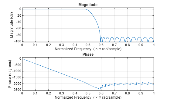
Create a minimum-order lowpass IIR halfband decimation filter. The filter has a transition width of 0.1859 in normalized frequency units and a stopband attenuation of 80 dB.
IIRHalfbandDecim = dsp.IIRHalfbandDecimator(... NormalizedFrequency=true,... TransitionWidth=0.1859,... DesignMethod='Quasi-linear phase')
IIRHalfbandDecim = dsp.IIRHalfbandDecimator with properties:
Main Specification: 'Transition width and stopband attenuation' TransitionWidth: 0.1859 StopbandAttenuation: 80 DesignMethod: 'Quasi-linear phase' NormalizedFrequency: true
Show all properties
Obtain the filter coefficients.
c = coeffs(IIRHalfbandDecim);
Plot the magnitude and phase response.
Use a halfband analysis filter bank and interpolation filter to extract the low frequency subband from a speech signal.
Note: The audioDeviceWriter System object™ is not supported in MATLAB Online.
Set up the audio file reader, the analysis filter bank, the audio device writer, and the interpolation filter. The sampling rate of the audio data is 22050 Hz. The halfband filter has an order of 21 and a transition width of 2 kHz.
afr = dsp.AudioFileReader('speech_dft.mp3',SamplesPerFrame=1024);
filterspec = "Filter order and transition width"; Order = 21; TW = 2000;
IIRHalfbandDecim = dsp.IIRHalfbandDecimator(... Specification=filterspec,FilterOrder=Order,... TransitionWidth=TW,SampleRate=afr.SampleRate);
IIRHalfbandInterp = dsp.IIRHalfbandInterpolator(... Specification=filterspec,FilterOrder=Order,... TransitionWidth=TW,SampleRate=afr.SampleRate/2);
ap = audioDeviceWriter(SampleRate=afr.SampleRate);
View the magnitude response of the halfband filter.
filterAnalyzer(IIRHalfbandDecim)
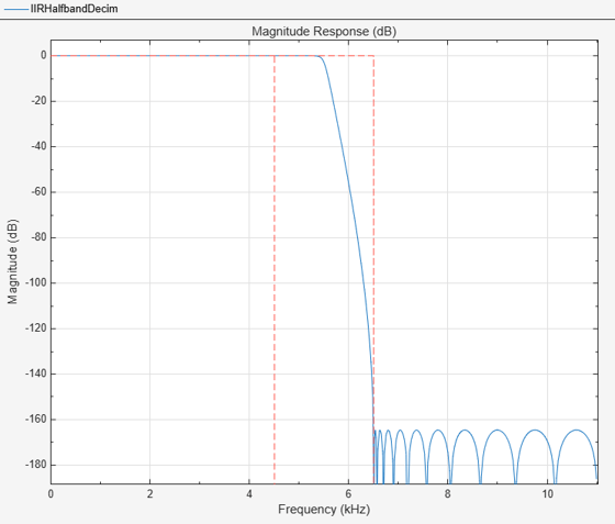
Read the speech signal from the audio file in frames of 1024 samples. Filter the speech signal into lowpass and highpass subbands with a halfband frequency of 5512.5 Hz. Reconstruct a lowpass approximation of the speech signal by interpolating the lowpass subband. Play the filtered output.
while ~isDone(afr) audioframe = afr(); xlo = IIRHalfbandDecim(audioframe); ylow = IIRHalfbandInterp(xlo); ap(ylow); end
Wait until the audio file ends, and then close the input file and release the audio output resource.
release(afr);
release(ap);
Design an elliptic IIR halfband decimator object of order 31 and a transition width of 0.1 using the designHalfbandIIR function. Set the Verbose argument to true.
hbIIR = designHalfbandIIR(FilterOrder=31,SystemObject=true,... Structure='decim',Verbose=true)
designHalfbandIIR(FilterOrder=31, DesignMethod="butter", Structure="decim", InputSampleRate="normalized", Datatype="double", SystemObject=true, Passband="lowpass")
hbIIR = dsp.IIRHalfbandDecimator with properties:
Main Specification: 'Coefficients' Structure: 'Minimum multiplier' HasPureDelayBranch: false AllpassCoefficients1: [8×1 double] AllpassCoefficients2: [7×1 double] HasTrailingFirstOrderSection: false
Show all properties
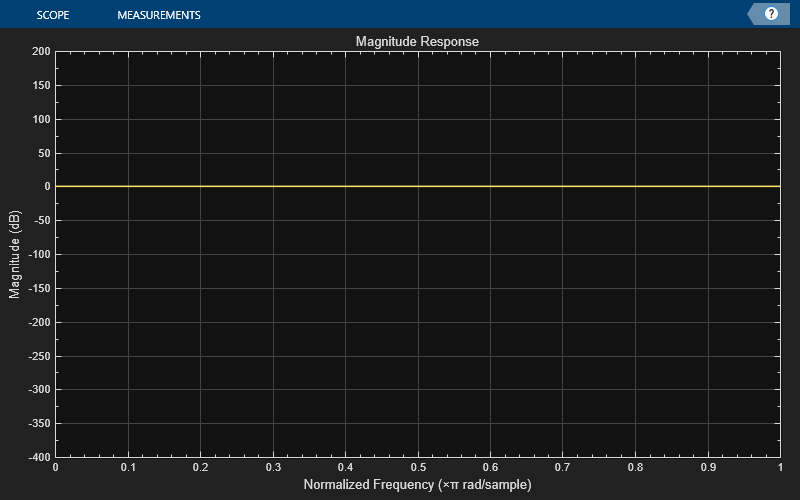
Create a dsp.DynamicFilterVisualizer object and visualize the magnitude response of the filter.
dfv = dsp.DynamicFilterVisualizer(NormalizedFrequency=true,YLimits=[-400 200]); dfv(hbIIR);
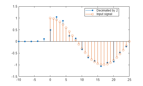
The input is a cosine wave.
Fs = 1; Fc = 0.03; input = cos(2piFc*(0:39)'/Fs);
Decimate the cosine signal using the IIR halfband decimator.
Plot the original and decimated signals. In order to plot the two signals in the same plot, you must account for the output delay introduced by the IIR halfband decimator and the scaling introduced by the filter. Use the outputDelay function to compute the delay introduced by the decimator. Shift the output by this delay value.
Visualize the input and the resampled signals. Due to the decimation factor of 2, the output samples coincide with every other input sample.
[delay,FsOut] = outputDelay(hbIIR,FsIn=Fs,Fc=Fc)
nInput = (0:length(input)-1); tOutput = (0:length(output)-1)/FsOut-delay; stem(tOutput,output,'filled',MarkerSize=4); hold on; stem(nInput,input); hold off; xlim([-10,25]) legend('Decimated by 2','Input signal','Location','best');
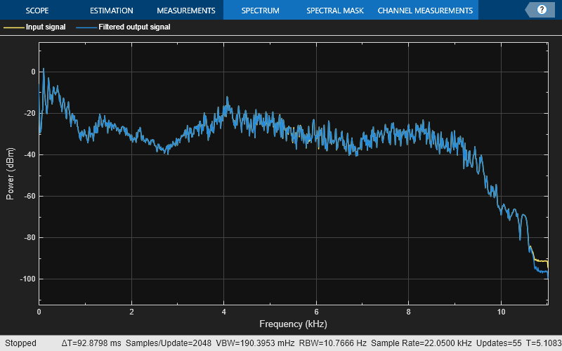
Use a halfband decimator and interpolator to implement a two-channel filter bank. This example uses an audio file input and shows that the power spectrum of the filter bank output does not differ significantly from the input.
Note: The audioDeviceWriter System object™ is not supported in MATLAB Online.
Set up the audio file reader and audio device writer. Construct the IIR halfband decimator and interpolator. Finally, set up the spectrum analyzer to display the power spectra of the filter-bank input and output.
AF = dsp.AudioFileReader('speech_dft.mp3',SamplesPerFrame=1024); AP = audioDeviceWriter(SampleRate=AF.SampleRate);
filterspec = "Filter order and transition width"; Order = 51; TW = 2000;
IIRHalfbandDecim = dsp.IIRHalfbandDecimator(... Specification=filterspec,FilterOrder=Order,... TransitionWidth=TW,SampleRate=AF.SampleRate);
IIRHalfbandInterp = dsp.IIRHalfbandInterpolator(... Specification=filterspec,FilterOrder=Order,... TransitionWidth=TW,SampleRate=AF.SampleRate/2,... FilterBankInputPort=true);
SpecAna = spectrumAnalyzer(SampleRate=AF.SampleRate,... PlotAsTwoSidedSpectrum=false,... ShowLegend=true,... ChannelNames={'Input signal','Filtered output signal'});
Read the audio 1024 samples at a time. Filter the input to obtain the lowpass and highpass subband signals decimated by a factor of two. This is the analysis filter bank. Use the halfband interpolator as the synthesis filter bank. Display the running power spectrum of the audio input and the output of the synthesis filter bank. Play the output.
while ~isDone(AF) audioInput = AF(); [xlo,xhigh] = IIRHalfbandDecim(audioInput); audioOutput = IIRHalfbandInterp(xlo,xhigh); spectrumInput = [audioInput audioOutput]; SpecAna(spectrumInput); AP(audioOutput); end
release(AF); release(AP); release(SpecAna);
Create a halfband decimator. Use a minimum-order design with a transition width of 0.0952 in normalized frequency units and a stopband attenuation of 60 dB.
IIRHalfbanddecim = dsp.IIRHalfbandDecimator(... NormalizedFrequency=true,... Specification='Transition width and stopband attenuation',... TransitionWidth=0.0952,... StopbandAttenuation=60);
Filter a two-channel input into lowpass and highpass subbands. The input signal can be of arbitrary frame size, that is, the number of input rows does not have to be a multiple of 2.
x = randn(1025,2); [ylow,yhigh] = IIRHalfbanddecim(x);
Algorithms
When you filter your signal, the IIR halfband decimator uses an efficient polyphase implementation for halfband filters. You can use the polyphase implementation to move the downsample operation before filtering. This change enables you to filter at a lower sampling rate.
IIR halfband filters are generally modeled using two parallel allpass filter branches.
Elliptic Design
The allpass filters for elliptic IIR halfband filter are given as
Quasi-Linear Phase Design
To achieve a near-linear phase response for IIR halfband filters, make one of the branches a pure delay. In this design, the cost of the filter increases.
The allpass filters for the quasi-linear phase IIR halfband filter are
where k is the length of the delay.
where N is the order of the IIR halfband filter.
You can represent filtering the input signal and then downsampling it by 2 using this figure.
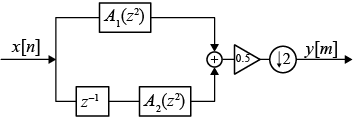
Using the multirate noble identity for downsampling, you can move the downsampling operation before the filtering operation. This change enables you to filter at a lower rate.
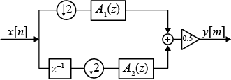
To implement the halfband decimator efficiently, this algorithm replaces the delay block and downsampling operator with a commutator switch. When the first input sample is delivered, the commutator switch feeds this input to the first branch and the halfband decimator computes the first output value. As more input samples come in, the switch delivers one sample at a time to each branch alternatively. The decimator generates output every time the first branch generates an output. This halves the sampling rate of the input signal.

Analysis Filter Bank
The transfer function of the complementary highpass filter branch of the analysis filter bank is given by:
You can represent the analysis filter bank as in this diagram.
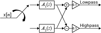
The IIR halfband decimator generates two power-complementary output signals by adding and subtracting the two polyphase branch outputs respectively.
For more information on filter banks, see Overview of Filter Banks.
To summarize, the IIR halfband decimator:
- Decimates the input prior to filtering.
- Acts as an analysis filter bank.
- Has a nonlinear phase response and uses few coefficients with the elliptic design method.
- Has near-linear phase response at the cost of additional coefficients with the quasi-linear phase design method, where one of the branches is a pure delay
References
[1] Lang, M. Allpass Filter Design and Applications. IEEE Transactions on Signal Processing. Vol. 46, No. 9, Sept 1998, pp. 2505–2514.
[2] Harris, F.J. Multirate Signal Processing for Communication Systems. Prentice Hall. 2004, pp. 208–209.
[3] Regalia, Phillip A., Sanjit K. Mitra, and P. P. Vaidyanathan. "The Digital All-Pass Filter: A Versatile Signal Processing Building Block." Proceedings of the IEEE. Vol. 76, Number 1, 1988, pp. 19-37.
Extended Capabilities
Version History
Introduced in R2015b
When you set the NormalizedFrequency property totrue, you must specify the transition width in normalized frequency units (0 to 1).
When you set the NormalizedFrequency property totrue while creating the object and you do not set the transition width, the object automatically sets the default transition width to normalized frequency units using the default sample rate of 44100 Hz.
iirhalfbanddecim = dsp.IIRHalfbandDecimator(NormalizedFrequency=true)
iirhalfbanddecim = dsp.IIRHalfbandDecimator with properties:
      Specification: 'Transition width and stopband attenuation'
    TransitionWidth: 0.1859
StopbandAttenuation: 80
       DesignMethod: 'Elliptic'
NormalizedFrequency: true
When you set the NormalizedFrequency property totrue after you create the object, you must specify the transition width in normalized units before you run the object algorithm.
iirhalfbanddecim = dsp.IIRHalfbandDecimator
iirhalfbanddecim = dsp.IIRHalfbandDecimator with properties:
      Specification: 'Transition width and stopband attenuation'
    TransitionWidth: 4100
StopbandAttenuation: 80
       DesignMethod: 'Elliptic'
NormalizedFrequency: false
         SampleRate: 44100
To specify the normalized frequency values, setNormalizedFrequency to true and manually convert the frequency values in Hz to normalized values using the input sample rate in Hz. For example, if the input sample rate is 44100 Hz, you can compute the corresponding values in normalized units using these equations.
iirhalfbanddecim.NormalizedFrequency = true; iirhalfbanddecim.TransitionWidth = 4100/(44100/2)
iirhalfbanddecim = dsp.IIRHalfbandDecimator with properties:
      Specification: 'Transition width and stopband attenuation'
    TransitionWidth: 0.1859
StopbandAttenuation: 80
       DesignMethod: 'Elliptic'
NormalizedFrequency: true
This object supports an input signal with an arbitrary frame length, so the input frame length does not have to be a multiple of the decimation factor 2.
When you generate code, to support arbitrary frame length for fixed-size signals, you must set the AllowArbitraryInputLength property totrue while generating code.
See Also
Functions
- freqz | freqzmr | filterAnalyzer | info | cost | polyphase | outputDelay | designHalfbandIIR