Meet Timing Requirements Using Enable-Based Multicycle Path Constraints - MATLAB & Simulink (original) (raw)
If your Simulink® model contains multiple sample rates or uses speed and area optimizations that insert pipeline registers, your design can have multicycle paths. Multicycle paths are data paths between two registers that operate at a sample rate slower than the FPGA clock rate and therefore take multiple clock cycles to complete their execution. To synchronize the clock rate to the sample rates of various paths in your design, you can use a single clock mode or a multiple clock mode. By default, HDL Coder™ uses a single clock mode that generates a single primary clock at the fastest sample rate and creates a timing controller entity to control the clock rate to the multicycle paths. The timing controller generates a set of clock enables with the required rate and phase information to control the sequential elements such asDelay blocks that operate at different sample rates.
When you synthesize the generated HDL code, synthesis tools can fail to meet the timing requirements of multicycle paths. The timing failure occurs because synthesis tools cannot infer the various sample rates in your design from the generated HDL code. The synthesis tools assume that the registers in your design run at the primary clock rate and requires data to travel between the registers within one clock cycle. However, the multicycle paths are not required to complete their execution within one clock cycle and therefore cannot meet the timing requirements. To meet the timing requirements, specify generation of enable-based multicycle path constraints.
How Enable-Based Multicycle Path Constraints Work
Synthesis tools require that data propagates from a source register to a destination register within one clock cycle. Multicycle path constraints relax this timing requirement by allowing multiple clock cycles for data to propagate between the registers. The code generator uses the timing controller enable signals to create enable-based register groups, with registers in each group driven by the same clock enable. When you apply the enable-based constraints and generate HDL code, the code generator outputs a constraints file with the naming conventiondutname_constraints. The file defines the timing requirements of multicycle paths and contains information about the setup and hold constraints that needs to be met.
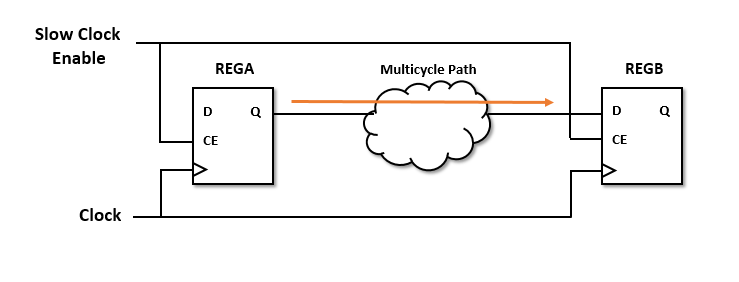
This figure shows a multicycle path that takes a certain number of clock cycles, say N, for the data to propagate fromREGA to REGB. By default, the synthesis tools define the setup edge at the next active clock edge and the hold edge at the same active clock edge with respect to the destination clock signal. For a multicycle path that takes N clock cycles, the constraints redefine the setup and hold edge to allow for the longer data propagation time.
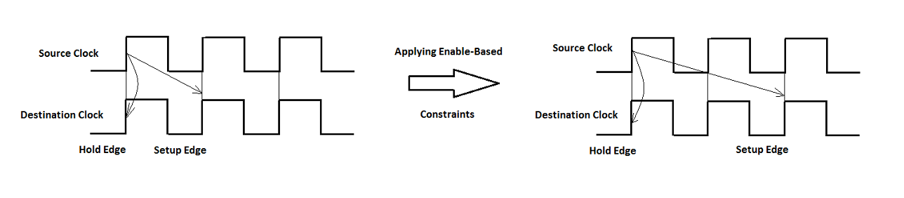
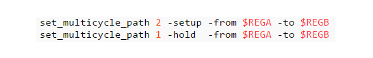
For example, consider a multicycle path takes two clock cycles for data to propagate from the source to the destination register. This waveform shows how applying enable-based constraints redefines the setup and hold edges. This code snippet shows this setup and hold requirement in the constraints file that gets generated when you enable multicycle path constraints.
Specify Enable-Based Constraints
Before you generate the enable-based constraints, you must:
- Preserve the multicycle paths in your design. Before you enable generation of multicycle path constraints, make sure that you disable optimizations such as clock rate pipelining and adaptive pipelining in those regions where you want to apply multicycle path constraints.
- Make sure that the region that operates at a slower clock rate is bounded by timing controller based clock enable signals operating at zero phase.
- Specify the Synthesis Tool. The format of the multicycle path constraints file that gets generated depends on the Synthesis tool that you specify. If you do not specify the synthesis tool and the Generate EDA scripts check box is selected, HDL Coder does not generate multicycle path constraints.
- Use the single clock mode. In the > pane, set Clock inputs to
Single.
You can specify generation of multicycle constraints in the Configuration Parameters dialog box, or in the HDL Workflow Advisor UI, or at the command line.
- In the Configuration Parameters dialog box, on the > pane, select the Enable-based constraints check box.
- In the HDL Workflow Advisor, on the > > task, select the Enable-based constraints check box.
- At the command line, use the
MulticyclePathConstraintsproperty withhdlset_paramormakehdl.
Benefits of Using Enable-Based Constraints
If the synthesis tools identify the multicycle path constraints, you can:
- Realize higher clock rates and improve the timing of your design.
- Reduce the area footprint on the target FPGA device because multicycle path constraints do not introduce any pipeline registers.
- Reduce HDL code generation time because the code generator does not have to run many optimization settings.
- Reduce synthesis time since multicycle path constraints relax the timing requirements on the synthesis tool.
- Skip verification of your design after generating HDL code as the generated model with the constraints is identical to the original model.
When you use the enable-based constraints setting:
- The generated constraints are more robust to name changes in synthesis tools.
- HDL code generation becomes faster.
- The Target workflow can be
Generic ASIC/FPGA,IP Core Generation, andSimulink Real-Time FPGA I/O. - The constraint file format is supported with these synthesis tool: Xilinx® ISE, Xilinx Vivado®, Altera® Quartus® II, and Cadence® Genus.
Modeling Guidelines
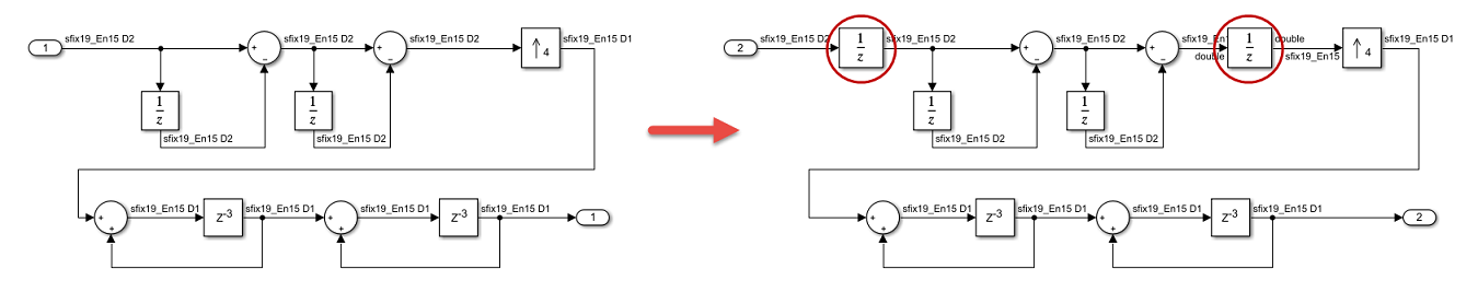
When you specify generation of enable-based constraints, use these modeling patterns in your design. If your model contains slow-rate regions that are not bounded by registers, then add delays at the same slow rate to the input and output of the slow-rate regions. For example, if you enter this command in the MATLAB® Command Window, you see a multirate CIC Interpolation filter implemented in single clock mode:
openExample('hdlcoder_clockdemo');
This figure shows how to bound the input and output of the slow-rate region annotated by the slow sample time D2 in the model withUnit Delay blocks so that the enable-based constraints can identify the slow-rate path.
Note
You can use Rate Transition blocks to introduce the input and output registers but make sure that the registers are slow rate and have zero phase.
Multicycle Path Constraints for Various Synthesis Tools
Enable-based multicycle path constraints have various file formats that depend on the Synthesis tool that you specify.
Altera Quartus II
HDL Coder generates the constraints in the form of an SDC file. This code snippet shows the SDC file generated for Altera Quartus II.
Multicycle constraints for clock enable: DUT_tc.u1_d4_o0
set enbreg [get_registers *u_DUT_tc|phase_0] set_multicycle_path 4 -to [get_fanouts $enbreg -through [get_pins -hier *|ena]] -end -setup set_multicycle_path 3 -to [get_fanouts $enbreg -through [get_pins -hier *|ena]] -end -hold
Cadence Genus
HDL Coder generates the constraints in the form of an SDC file. This code snippet shows the SDC file generated for Cadence Genus.
Multicycle constraints for clock enable: MCP_Subsystem_tc.u1_d5_o0
set MCPnet0 [get_db hnets .name *u_MCP_Subsystem_tc/phase_0] set MCPreg0 [get_cells -of [all_fanout -flat -endpoints_only -from $MCPnet0]] set_multicycle_path 5 -setup -from MCPreg0−toMCPreg0 -to MCPreg0−toMCPreg0 set_multicycle_path 4 -hold -from MCPreg0−toMCPreg0 -to MCPreg0−toMCPreg0
Xilinx Vivado
HDL Coder generates the constraints in the form of an XDC file. This code snippet shows the XDC file generated for Xilinx Vivado.
Multicycle constraints for clock enable: DUT_tc.u1_d4_o0
set enbregcell [get_cells -hier -filter {mcp_info=="DUT_tc.u1_d4_o0"}] set enbregnet [get_nets -of_objects [get_pins -of_objects $enbregcell -filter {DIRECTION == OUT}]] set reglist [get_cells -of [filter [all_fanout -flat -endpoints_only $enbregnet] IS_ENABLE]] set_multicycle_path 4 -setup -from reglist−toreglist -to reglist−toreglist -quiet set_multicycle_path 3 -hold -from reglist−toreglist -to reglist−toreglist -quiet
The multicycle path constraints form enable-based register groups by querying the synthesis netlist for the ATTRIBUTE keyword. When you run any of the supported target workflows, this code snippet shows this keyword in the synthesis netlist.
... ATTRIBUTE mcp_info: string
ATTRIBUTE mcp_info OF phase_0 : SIGNAL IS "DUT_tc.u1_d4_o0"; ...
The constraints file that is generated for Xilinx Vivado is more robust than pattern matching on module or signal names.
Xilinx ISE
HDL Coder generates the constraints in the form of a UCF file. This code snippet shows the UCF file generated for a model that has one slow-rate region controlled by a clock enable signal and has a target frequency of 300MHz. The multicycle path constraints depend on the Target Frequency that you specify.
Multicycle constraints for clock enable: DUT_tc.u1_d4_o0
NET "*u_DUT_tc/phase_0" TNM_NET = FFS "TN_u_DUT_tc_phase_0"; TIMESPEC "TS_u_DUT_tc_phase_0" = FROM "TN_u_DUT_tc_phase_0" TO "TN_u_DUT_tc_phase_0" TS_FPGA_CLK/4;
The clock constraints that are generated when you run the Generic ASIC/FPGA, or the Simulink Real-Time FPGA I/O workflow with Xilinx ISE are shown in this code.
Timing Specification Constraints
NET "clk" TNM_NET = "TN_clk"; TIMESPEC "TS_FPGA_CLK" = PERIOD "TN_clk" 300 MHz;
To use the multicycle path constraints when you generate HDL code by using themakehdl function, make sure that you add aTS_FPGA_CLK constraint to the UCF file.
Preserve Enable Signals in Timing Control Logic
When you apply enable-based multicycle path (MCP) constraints to relax the timing constraints on multicycle data paths, HDL Coder generates MCP with timing controller logic. If you source enable-based constraints to the synthesis tool, the synthesis tool optimizes this timing controller logic to convert it to the single clock domain design. The MCP constraints are not applied in the generated HDL code. To preserve this timing control logic in the synthesis tool, HDL Coder adds an attribute direct_enable to all of the enable signals in your generated timing controller HDL code.
This generated VHDL® code shows the direct_enable attribute is added to the enable signal in timing controller logic:
... ATTRIBUTE direct_enable OF enb_1_1_1: SIGNAL IS "yes"; ...
This generated Verilog® code shows the direct_enable attribute is added to the enable signal in timing controller logic:
... (* direct_enable = "yes" *) output enb_1_1_1; ...
Due to the direct_enable attribute, the MCP constraints are applied to your design when you source MCP constraints in the synthesis tool.
Limitations
- The multicycle path constraints file is not supported with the
FPGA-in-the-Loopworkflow. - If the slow-rate region is not bounded by registers, multicycle path constraints require that you to add two Delay blocks at the slow rate, which increases the latency of your design.
- The code generator does not add constraints on paths between registers that have a nonzero phase value for the timing controller-based enable signals. For the code generator to add constraints, use registers that derive from phase
0clock enable signals, such asDelay blocks. - The generated multicycle constraints can be less effective if you apply the constraints to regions that have optimizations such as clock-rate pipelining and adaptive pipelining enabled. With clock-rate pipelining, the registers operate at the faster clock rate and might not retain the slow-rate registers in your design.
- HDL Coder does not generate multicycle path constraints for single-rate models.
- If you use the multiple clock mode, the code generator does not output the multicycle path constraints file.