telecom transmitters (original) (raw)
Acronym: Tx
Definition: devices that generate light signals from digital electrical signals
Alternative terms: data transmitters, senders, optical transmitters, optoelectronic transmitters
Category:  lightwave communications
- optical data transmission
- telecom transmitters
* LED transmitters
* laser transmitters
* directly modulated transmitters
* externally modulated transmitters
* coherent transmitters
* integrated photonics transmitters
* free-space optical transmitters - free-space optical communications
- optical fiber communications
- telecom transmitters
Related: optical data transmissionoptical fiber communicationstelecom receiverstelecom transceivers
Opposite term: telecom receivers
DOI: 10.61835/00v Cite the article: BibTex BibLaTex plain textHTML Link to this page! LinkedIn
Content quality and neutrality are maintained according to our editorial policy.
📦 For purchasing telecom transmitters, use the RP Photonics Buyer's Guide — an expert-curated directory for finding all relevant suppliers, which also offers advanced purchasing assistance.
Contents
Introduction to Telecom Transmitters
External Modulation Techniques
Transmitter Packaging and Form Factors
Optical Transmitters for Test and Measurement
Summary:
This article offers an in-depth introduction to optical telecom transmitters, devices generating and modulating light for fiber-optic and free-space links. It explains the basic structure and function—from driver electronics, light sources (LEDs and laser diodes such as FP, DFB/DBR, VCSELs), and optical coupling with isolation, to monitoring and control (APC, temperature and wavelength control, digital diagnostics). Key topics include wavelength regions (850/1310/1550 nm), modulation formats (NRZ, PAM4, QPSK/16-QAM for coherent), and external modulation with Mach–Zehnder and electroabsorption modulators. The article discusses transmitter characterization (eye diagram, extinction ratio, RIN, phase noise, TDP), packaging and form factors from TOSA through pluggable modules (SFP, QSFP, CFP, OSFP) and PIC-based designs, as well as integration trends like silicon photonics and co-packaged optics (CPO). It also covers transceivers that combine Tx/Rx, outlines future research (energy-efficient, tunable and heterogeneous sources, LiFi/FSO), and describes test & measurement transmitters for device and coherent-system evaluation.
(This summary was generated with AI based on the article content and has been reviewed by the article’s author.)
Optical data transmission uses transmitter devices for sending digital signals in the form of light — typically, it sends near-infrared light into an optical transmission fiber (telecom fiber) or into free space (→ free-space optical communications). Such transmitters are driven by suitable electronics that supply the data stream and condition the drive signal.
There are also analog transmitters for RF transmission, but this article focuses on optical transmitters for digital signals. Non-telecom transmitters such as transmitters for very low data rates (e.g. TV remote controls) are also not treated here.
A transmitter module often comprises not only the optical source, but also additional optical components that deliver the light in the desired form — for example, as a collimated beam for free-space transmission. In some cases, an optical amplifier is also included, e.g. a SOA or (for high powers) an EDFA, or on-chip.
Transmitters can also be implemented in photonic integrated circuits (PICs), e.g. based on silicon photonics, InP, or hybrid integration platforms. Multiple lasers, modulators, multiplexers, and couplers can be integrated on a single chip. This enables compact, low-power, high-speed, and cost-effective designs. Integration with co-packaged optics (CPO) and electronic integrated circuits is an emerging trend for next-generation data centers and 6G systems.
At the opposite end of the link, the optical signal is detected with a telecom receiver, which converts it back into an electrical data signal.
Optical transmitters are essential components of systems such as:
- telecommunication networks: fiber-optic networks used as long-haul and metropolitan optical backbones, including submarine fiber-optic links
- data communications: Ethernet links within and between data centers
- access networks: passive optical networks (GPON, XGS-PON, NG-PON2)
- cable TV and analog distribution: RF-over-fiber systems
- free-space optical communications
There are also optical transmitters for other application areas, such as sensing and measurement (e.g. fiber-optic sensors for distributed temperature or strain sensing) and LIDAR.
Basic Structure and Function
A typical optical transmitter comprises the following main parts:
- Driver electronics receive digital or analog data from upstream circuits and convert logic-level signals into precisely shaped, high-speed current or voltage waveforms suitable for driving the optical source.
- Light source: This is usually a semiconductor laser diode or a light-emitting diode (LED). The source may be directly modulated (i.e., its optical power, optical phase, or polarization is varied according to the data) or it may emit continuous, unmodulated light that is then sent to an external optical modulator (see below for more details). External modulation often allows for higher performance because it avoids certain side effects of directly modulating the laser (e.g. chirp).
- Optical coupling elements (e.g. a lens or waveguide structure) feed the light efficiently into an optical fiber. A Faraday isolator may be used to prevent back-reflections from destabilizing the laser.
- Monitoring and control circuitry may include various functions:
- Automatic power control (APC) keeps the output power constant.
- Temperature control (often via thermoelectric coolers) avoids wavelength drifts due to temperature changes or aging.
- Wavelength tuning in tunable transmitters, used for flexible network reconfiguration, is controlled by thermal or electronic means.
- Digital diagnostics (DDM) monitor optical power, bias current, and temperature via I2C interfaces in pluggable modules.
Transceivers
In many systems, the optical transmitter is combined with a receiver in a single device, called an optical transceiver. Such transceivers enable bidirectional data transmission, using either two fibers (one for each direction) or a single fiber with different wavelengths for transmitting and receiving.
Typical transceivers are often realized as pluggable modules, containing both the transmitter and receiver together with control electronics and digital diagnostics (e.g., via an I²C interface). Increasingly, optical transceivers are implemented as photonic integrated circuits, combining lasers, modulators, detectors, and wavelength-division multiplexers on a single chip. Optical co-packaging (OCP) is another trend, leading to transceivers integrated into routers and switches.
Technical Details
Wavelength Regions
Optical transmission typically works in standard wavelength regions — particularly in case optical fiber communications, where wavelength-dependent propagation losses and chromatic dispersion need to be considered.
Common wavelength regions are:
- 850 nm: suitable for multimode fibers as used in short-range (LAN/data center), but also for free-space transmission
- 1310 nm: in the zero-dispersion region of silica fibers, used for metro and access networks
- 1550 nm: minimum fiber attenuation, compatible with erbium-doped fiber amplifiers (EDFAs), used for long-haul and DWDM systems, also often chosen for free-space transmission with relatively eye-safe lasers
Modulation Formats
Different modulation formats can be employed, as explained in the article on optical data transmission. Simple systems often use intensity (power) modulation, while advanced coherent techniques such as quadrature amplitude modulation (QAM) or QPSK exploit amplitude and phase — and sometimes polarization — to achieve higher data rates within a given spectral bandwidth.
The following table gives a brief overview of the use of digital modulation formats:
| Application | Typical format | Data rate | Example technology |
|---|---|---|---|
| Ethernet | NRZ or PAM4 | 10–400 Gb/s | VCSEL |
| Metro DWDM | OOK or DPSK | 10–40 Gb/s | DFB + EAM |
| Long-haul | QPSK / 16-QAM (coherent) | 100–800 Gb/s | DFB/DBR + MZM |
| Data center | PAM4 | 50–800 Gb/s | VCSEL or SiPh Tx |
Spectral efficiency (data rate per unit bandwidth) is a crucial figure of merit, especially for fiber links with many wavelength channels (DWDM). It depends strongly on the chosen modulation format and on the linearity of the transmitter chain.
Optical Sources
The used optical sources can have different characteristics:
- Output power: typically ranges from −10 dBm (0.1 mW) in short links to +20 dBm (100 mW) or more in long-haul systems.
- Linearity is critical for analog or multilevel digital modulation (PAM4, QAM).
- Temperature effects may need to be compensated through closed-loop bias and power control.
- Eye diagram and extinction ratio are key performance indicators for intensity-modulated transmitters.
Typical types of light emitters are explained in the following:
Light-emitting Diodes (LEDs)
Light-emitting diodes are the simplest and least expensive light sources for data transmission with direct intensity modulation. They can be driven with relatively simple electronics and offer high reliability. However, compared to lasers they have limited coherence:
- Their spatial coherence is limited by the relatively large emitting area, which restricts efficient coupling into single-mode fibers; even with multimode fibers the coupling efficiency is not ideal.
- Their temporal coherence is low, related to the broad optical bandwidth.
As a result, LED-based transmitters are mainly used for short-distance, low-speed single-channel links — typically up to a few hundred Mbps over a few kilometers. Often, the ultimate reach is limited not only by the LED itself but also by intermodal dispersion of multimode fibers, which can be mitigated using graded-index fibers.
Laser Diodes
Laser diodes are more advanced light sources, providing light with high spatial and temporal coherence and substantial optical power. Typical laser types used in communications are:
- Fabry–Pérot lasers (FP lasers) are the simplest type. Due to multimode emission, they are limited to low-cost short links with moderate data rates.
- Distributed feedback lasers (DFB lasers) provide robust single-frequency output with a stable wavelength. They are widely used in telecom systems, including long-haul systems.
- Distributed Bragg reflector lasers (DBR lasers) are similar to DFB lasers, but can contain separate tuning and gain sections for better wavelength agility.
- Vertical-cavity surface-emitting lasers (VCSELs) are compact, low-cost lasers. Their output allows for easy single-mode fiber coupling, and they can be modulated directly at high speeds. VCSELs are dominant in data center short-reach links at 850 nm or 1310 nm.
Some laser diodes (often of DBR type) are tunable lasers. Advanced designs with narrow linewidths and wide wavelength agility are suitable for dense wavelength division multiplexing (DWDM) systems. For example, while simple fixed-wavelength lasers can be used for DWDM, advanced tunable lasers are ideally suited for providing redundancy in case of a laser failure, or for flexible channel allocation.
External Modulation Techniques
As mentioned above, some transmitters contain an unmodulated laser source combined with an optical modulator. This architecture supports very high data rates and excellent signal integrity, because external modulation reduces chirp and chromatic dispersion penalties and thus enables longer transmission distances.
Common modulator types are:
- Mach–Zehnder modulators (MZM) are often based on lithium niobate (LiNbO3) or on silicon photonics. Their operation principle is that one modulates the phase difference between two optical paths to yield intensity or phase modulation. This principle is suitable for high-speed (>40 Gb/s) and coherent modulation formats.
- Electroabsorption modulators (EAM) contain a semiconductor device whose absorption changes with applied voltage. They are very compact and can be integrated with the laser diode. They are common in 10–40 Gb/s metro links.
Transmitter Characterization
The performance of an optical transmitter is assessed through a number of key characterization parameters, which describe the quality, stability, and fidelity of the transmitted optical signal. Important figures include the eye diagram, extinction ratio, relative intensity noise (RIN), and transmitter dispersion penalty (TDP); these are explained in the following.
Eye Diagram
An eye diagram is a graphical representation of a repetitive digital signal, obtained by overlaying multiple bit periods on an oscilloscope. For optical transmitters, the eye diagram shows how clearly the optical power levels representing logical “1” and “0” can be distinguished over time. A wide-open eye indicates good signal integrity, with low noise and distortion. Eye closure can result from timing jitter, noise, bandwidth limitations, or chromatic dispersion (after some length of transmission fiber).
Parameters often extracted from the eye diagram include:
- eye opening (height and width) — indicating signal amplitude and timing margin
- rise and fall times
- jitter — timing variations of signal transitions
- signal-to-noise ratio (SNR)
Eye diagrams may be recorded directly after a transmitter or after some length of transmission fiber. Note that the degradation caused by the transmission fiber can substantially depend on the qualities of the transmitter, in particular due to chirp for directly modulated transmitter lasers; for details, see the explanations on “transmitter dispersion penalty” below.
Extinction Ratio
The extinction ratio (ER) quantifies how effectively the transmitter distinguishes between optical “1” and “0” levels. It is defined as the logarithmic ratio of the average optical power of the “1” level (($P_2$)) to that of the “0” level (($P_0$)): \textrm{ER} = 10 \lg \frac{P_1}{P_0}$$
in units of decibels (dB).
In practice, ER values of 6–10 dB are typical for directly modulated transmitters, while externally modulated systems can achieve >20 dB.
Poor extinction ratios lead to smaller eye openings and increased bit error rates (BER).
Intensity Noise
Intensity noise refers to random fluctuations of the emitted optical power. For continuous-wave lasers (as used in systems with an external optical modulator), this noise is commonly characterized by the relative intensity noise (RIN), which arises from spontaneous emission and other intrinsic laser noise mechanisms. RIN is expressed as a power spectral density of the optical power fluctuations relative to the average optical power, usually in units of dB/Hz. (See the article on relative intensity noise for more details.) A low RIN value (e.g., < −150 dB/Hz) is desirable for high-performance transmitters.
In directly modulated lasers, the situation is more complex. The emitted power noise results not only from intrinsic laser fluctuations but also from the electrical drive signal, which is harder to stabilize than a constant bias current. Moreover, the modulation process itself excites relaxation oscillations, coupling the laser's dynamic response to the modulation waveform.
Intensity noise directly degrades the signal-to-noise ratio (SNR) at the receiver, although it is not the only contributing noise source. It can become particularly critical for multilevel modulation formats (e.g., PAM4) and analog transmission systems (e.g., RF-over-fiber), where amplitude accuracy is essential.
Phase Noise
Phase noise (fluctuations of the optical phase) is most important for coherent transmission systems, but can also be relevant in intensity-modulated direct-detection systems, where phase variations indirectly affect intensity or chirp through chromatic dispersion in the transmission fiber.
In a directly modulated laser (DML), the injection current is varied to modulate the optical power. However, the carrier density and refractive index of the gain medium are coupled via the linewidth enhancement factor (α-factor). As a result, the emitted light experiences frequency chirp — a deterministic modulation of the instantaneous frequency during each bit transition. This effect is sometimes referred to as chirp-induced phase noise, although it is not truly random. While chirp causes only minor spectral broadening in short links, in longer fibers the combination of chirp and chromatic dispersion leads to eye closure and intersymbol interference, limiting transmission reach. These effects can be mitigated by using low-α lasers or by optimizing the bias and modulation parameters.
For transmitters using a continuous-wave (CW) laser and an external modulator, the laser itself generally exhibits low phase noise, related to its emission linewidth. The modulator ideally produces only intensity modulation (AM), but in practice small residual phase modulation occurs — for example, due to imperfect biasing of Mach–Zehnder modulators or voltage-induced refractive index changes in an electroabsorption modulator (see also the article on Kramers–Kronig relations). EAMs in particular exhibit significant amplitude–phase coupling and nonzero chirp even under ideal bias conditions.
In coherent systems, both the amplitude and phase of the optical field carry information. Here, the combined linewidth of the transmitter and local-oscillator lasers must be sufficiently narrow for phase estimation in the digital signal processing (DSP) to track it. Excess phase noise causes constellation rotation and intersymbol interference. Typical coherent systems require laser linewidths below 100–300 kHz for 100 Gb/s DP-QPSK, and even narrower for higher-order QAM formats.
Transmitter Dispersion Penalty
The transmitter dispersion penalty (TDP) quantifies the additional optical power required to achieve the same bit error rate in the presence of chromatic dispersion, compared with a reference back-to-back measurement. It accounts for the combined effects of transmitter chirp, spectral width, and fiber dispersion on signal degradation.
TDP is typically expressed in dB and measured by sending data through a defined length of standard fiber and comparing receiver sensitivity to the back-to-back case. A low TDP (close to 0 dB) indicates a transmitter well matched to the dispersion characteristics of the transmission link, or exhibiting very low chirp. High TDP values (e.g., > 2 dB) imply performance degradations at longer distances or higher data rates.
Transmitter Packaging and Form Factors
Optical transmitters are produced in a variety of packaging formats, depending on the intended application, integration level, and required performance. In modern communication equipment, the physical realization of a transmitter is often as important as its internal technology, because packaging affects thermal behavior, coupling efficiency, reliability, and system compatibility.
Transmitter Optical Sub-Assembly
The Transmitter Optical Sub-Assembly (TOSA) is the core optoelectronic package that houses the light-generating and coupling components of an optical transmitter. A typical TOSA includes:
- the light source (laser diode or LED)
- any associated monitor photodiode for power feedback
- an optical coupling interface such as a precision lens, ferrule, or fiber pigtail
- electrical connections for the laser driver
- optional temperature control elements (e.g., thermistor, thermoelectric cooler)
TOSAs are often designed to meet strict alignment tolerances, ensuring efficient and stable optical coupling to the external fiber connector (typically LC, SC, or MPO). They are manufactured as sealed, hermetic packages or molded subassemblies, depending on performance and cost requirements.
For transceivers, the TOSA is complemented by a Receiver Optical Sub-Assembly (ROSA), which houses the photodiode and receiver front-end. In bidirectional modules, the transmit and receive paths may share a single optical port using a wavelength splitter.
Integration into Pluggable Transceivers
In contemporary network equipment, optical transmitters are rarely stand-alone devices. Instead, they are integrated into standardized pluggable transceiver modules, which contain both the transmitter (TOSA) and receiver (ROSA) sections, together with driver electronics, digital diagnostics, and control interfaces (e.g. via I²C).
Common pluggable form factors include:
| Form factor | Typical data rate | Description |
|---|---|---|
| SFP / SFP+ | up to 10–28 Gb/s | Compact form used in access and metro networks |
| QSFP / QSFP+ / QSFP28 / QSFP-DD | 40–400 Gb/s and higher | Quad-channel variants used in data centers and short-reach interconnects |
| CFP / CFP2 / CFP4 | 100–400 Gb/s | Larger modules for long-haul coherent systems |
| OSFP | up to 800 Gb/s | Modern form factor for next-generation Ethernet and AI clusters |
Each pluggable transceiver conforms to a multi-source agreement (MSA) that defines its mechanical dimensions, electrical interface, and management functions. Inside these modules, the TOSA may be implemented as:
- a discrete sub-assembly mounted on a printed circuit board, or
- a monolithically integrated photonic chip, in newer silicon photonics or InP-based designs.
Standardization by bodies such as the Optical Internetworking Forum (OIF) and IEEE 802.3 ensures interoperability between module vendors and host systems.
Especially coherent transmitters may also contain electronics for forward error correction (FEC), implemented within their integrated digital signal processors. In contrast, transmitters for direct-detection systems usually do not include FEC functionality; it is typically realized externally, for example in an Ethernet switch ASIC or host interface chip.
Future Trends and Research
Optical transmitters are already used for many years, but the development continues at high pace:
- Coherent optical transmitters for highest data rates are already well established, but are continuously improved further.
- Silicon photonics integration reduces cost and size by leveraging CMOS fabrication.
- Quantum-dot lasers and heterogeneous integration are pursued for stable, narrow-linewidth optical sources.
- Energy-efficient designs using lower drive voltages, advanced modulation (PAM8, CAP, probabilistic shaping) and other techniques are receiving increased interest.
- Optical wireless (LiFi, FSO) transmitters with LEDs and laser arrays increasingly enable high-speed wireless optical links.
Techniques for transmitter packaging and integration are also developed further:
- Photonic integration allows combining the laser, modulator, multiplexer, and monitor functions in one compact package, reducing assembly cost and footprint.
- Co-packaged optics (CPO) place the optical sub-assemblies directly adjacent to high-speed electronic ASICs on a common substrate to minimize electrical interconnect losses and power consumption.
- For high-volume data center applications, simplified chip-on-board or connectorized TOSA designs are increasingly replacing traditional hermetic packages.
Optical Transmitters for Test and Measurement
Specialized optical transmitter modules are used in test and characterization systems rather than in data transmission links. For example, such a device can be combined with a vector network analyzer (VNA) to extend signal generation from the RF and microwave domain into the optical domain. These setups enable electro-optic or opto-electronic frequency-response measurements of high-speed components such as photodiodes, telecom receivers, or — when used together with a suitable photodetector — optical modulators. They allow determination of the amplitude and phase transfer characteristics (S-parameters) of the device under test with bandwidths reaching tens of gigahertz.
High-performance research transmitters are used for generating complex modulation signals in coherent communication experiments. Such systems may employ dual-polarization IQ modulators driven by high-speed arbitrary waveform generators, enabling device and system tests with modulation formats such as M-QAM and M-PSK. Some support investigations of terabit-class transmission systems and component testing under realistic signal conditions.
Frequently Asked Questions
This FAQ section was generated with AI based on the article content and has been reviewed by the article’s author (RP).
What is an optical telecom transmitter?
An optical telecom transmitter is a device that sends signals as light, typically into an optical fiber or free space. It converts an electrical data stream into a modulated optical signal for optical data transmission.
What are the main components of a telecom transmitter?
A typical transmitter includes driver electronics, a light source like a laser diode or LED, optical coupling elements, and monitoring and control circuitry for power, temperature, and wavelength stabilization.
What kinds of light sources are used in optical transmitters?
What is the difference between direct and external modulation in a transmitter?
In direct modulation, the light source itself is turned on and off or varied. In external modulation, a continuous-wave laser is used with a separate optical modulator. External modulation offers higher performance by reducing chirp and enabling longer transmission distances.
What are the common wavelength regions for telecom transmitters?
Transmitters typically operate at 850 nm for short-range links, 1310 nm for metro networks (near the zero-dispersion point of silica fibers), and 1550 nm for long-haul systems where fiber attenuation is minimal.
What is the role of photonic integrated circuits in modern transmitters?
Photonic integrated circuits allow for the integration of multiple optical components like lasers, modulators, and multiplexers on a single chip. This leads to more compact, power-efficient, and cost-effective transmitters for high-speed systems.
Why are different modulation formats like PAM4 and QPSK used?
Advanced modulation formats such as PAM4, QPSK, and QAM are used to increase the spectral efficiency: They encode more data bits per symbol, allowing for higher data rates within a limited optical bandwidth, which is crucial for wavelength division multiplexing (DWDM) systems.
How is transmitter performance characterized?
Important figures include the eye diagram, extinction ratio, relative intensity noise (RIN), and transmitter dispersion penalty (TDP).
Suppliers
Sponsored content: The RP Photonics Buyer's Guide contains 38 suppliers for telecom transmitters. Among them:

⚙ hardware🧩 accessories and parts🧴 consumables🔧 maintenance, repair

Our Optical Multi-Format Transmitter (OMFT) is built for researchers who require high signal fidelity for the generation of dual polarization IQ signals. Today, with up to 60 GHz bandwidth, it supports next-generation multi-level transmission formats such as M-QAM, M-PSK and custom modulation formats at symbol rates beyond 100 Gbaud/s for the generation of signals in the terabit/s regime. Our in-house developed Automatic Bias Controller (ABC) takes the complexity out of bias control. It automatically sets and maintains the optimal operating point for Mach-Zehnder modulators, ensuring consistent performance over time and conditions.

⚙ hardware
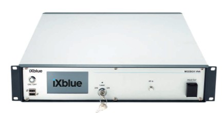
The ModBox-VNA by Exail is a wide bandwidth optical transmitter designed to extend vectorial network analyzer applications into the optical domain. When associated with a vectorial network analyzer, they reach a high performance and easy to use test equipment for photodiodes, photoreceivers or any high speed optoelectronic device characterization.
Questions and Comments from Users
Here you can submit questions and comments. As far as they get accepted by the author, they will appear above this paragraph together with the author’s answer. The author will decide on acceptance based on certain criteria. Essentially, the issue must be of sufficiently broad interest.
Please do not enter personal data here. (See also our privacy declaration.) If you wish to receive personal feedback or consultancy from the author, please contact him, e.g. via e-mail.
By submitting the information, you give your consent to the potential publication of your inputs on our website according to our rules. (If you later retract your consent, we will delete those inputs.) As your inputs are first reviewed by the author, they may be published with some delay.